Globestock G.Winch User manual

SERVICE MANUAL
G.Winch
Issue: 003
Date: 03/08/21

Contents
Manual Overview
G.Winch
Disassembly & Assessment
Reassembly
Testing
Brake Thickness Table
Assembly Drawing
3
4
5
7
10
12
13
www.globestock.co.uk +44(0) 1691 654 966
Globestock Ltd, Mile Oak Industrial Estate, Maesbury Road, Oswestry, Shropshire, SY10 8GA UK
Covered Models: 070 G.Winch
NOTE: This manual is only a basic reference for fully trained and
approved personnel. It cannot replace training.
Beforecarryingoutanywork,rstidentifytheunit,thenreferto
therelevantsub-assemblyandnalassemblydrawings.
Topic Page
2
The correct PPE must be worn before attempting to service Globestock equipment,
including:
• Safety shoes
• Safety glasses
• Gloves
• Overalls
• Ear defenders
• Valved dust mask

Manual Overview
Hand Operated Winch
Overview
The G.Winch requires detailed annual inspections and testing. The inspection and
servicemustbecarriedoutbycertiedGlobestocktrainedserviceagentsonly.
G.Winch models are divided into 4 separate max working loads with varying wire
rope materials and lengths:
*XX is replaced with rope length, e.g. 50 metre model = GSE070-136-50
Each G.Winch model has the same physical construction and brake settings, the
onlysignicantdierencebetweenthe4modelsistheconstructionofthewirerope.
Using This Manual
Thismanualisseparatedintothe3dierentmodeltypesforquickreference.
Disassembly and assessment
This will guide the service agent on how to safely disassemble a unit and
how to inspect and evaluate each critical component.
Reassembly
This will guide the service agent on how to correctly rebuild the unit in a safe
andecientmanner.
Testing
This will guide the service agent on how to inspect and test all units using the
correctequipmenttogaina12-monthcertication.
Max Working Load
(KG)
Wire Rope Material Rope Lengths
(m)
GSE070-136-XX* 136 Stainless Steel 15 - 50
GSE070-150-XX* 150 Galvanised Steel 15 - 50
GSE070-200-XX* 200 Stainless Steel 15 - 40
GSE070-250-XX* 250 Galvanised Steel 15 - 40
3

4
Disassembly & Assessment
1. GENERAL CONDITION
It is important to ensure the winch is safe to handle before work
commences. Firstly, inspect the condition of the housing and the drum
ensuring all fasteners are present and secure.
Any G.Winch units that:
- Do not pass basic function test.
- The winch body / frame is out of alignment, bent or damaged.
- Require stripping down of the winch body.
Are beyond the scope of this manual. These units should be returned
to Globestock for repair work to be assessed and completed. The
bodyalignmentisdicultandincorrectalignmentmaycausea
release of the lifted load during use.
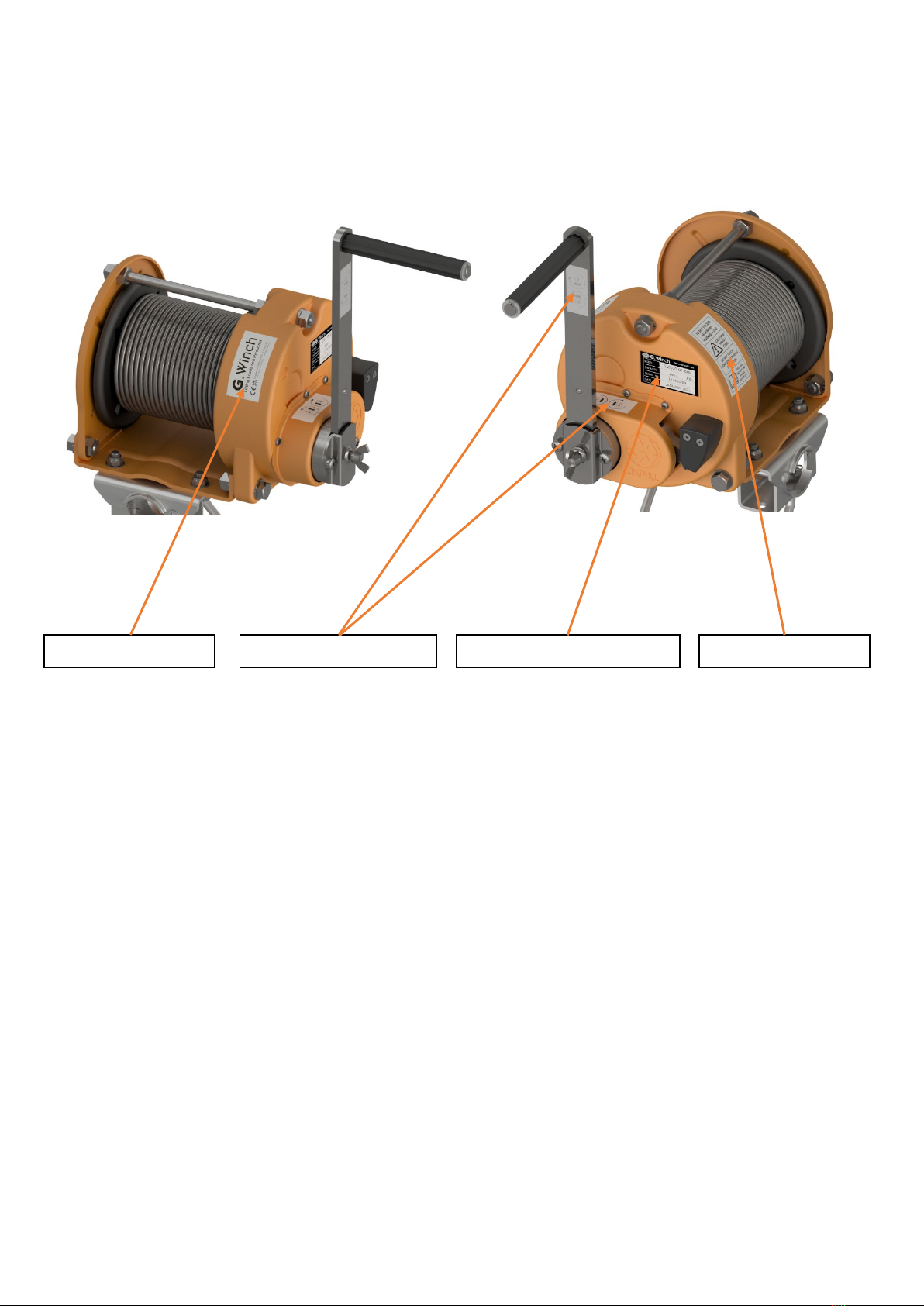
2. INSPECT IDENTITY LABEL
This can be found on the side of the housing. Take note of the wire
rope length, material and maximum working load. Make sure the
label is legible and fully attached. If there is any damage the label
must be replaced.
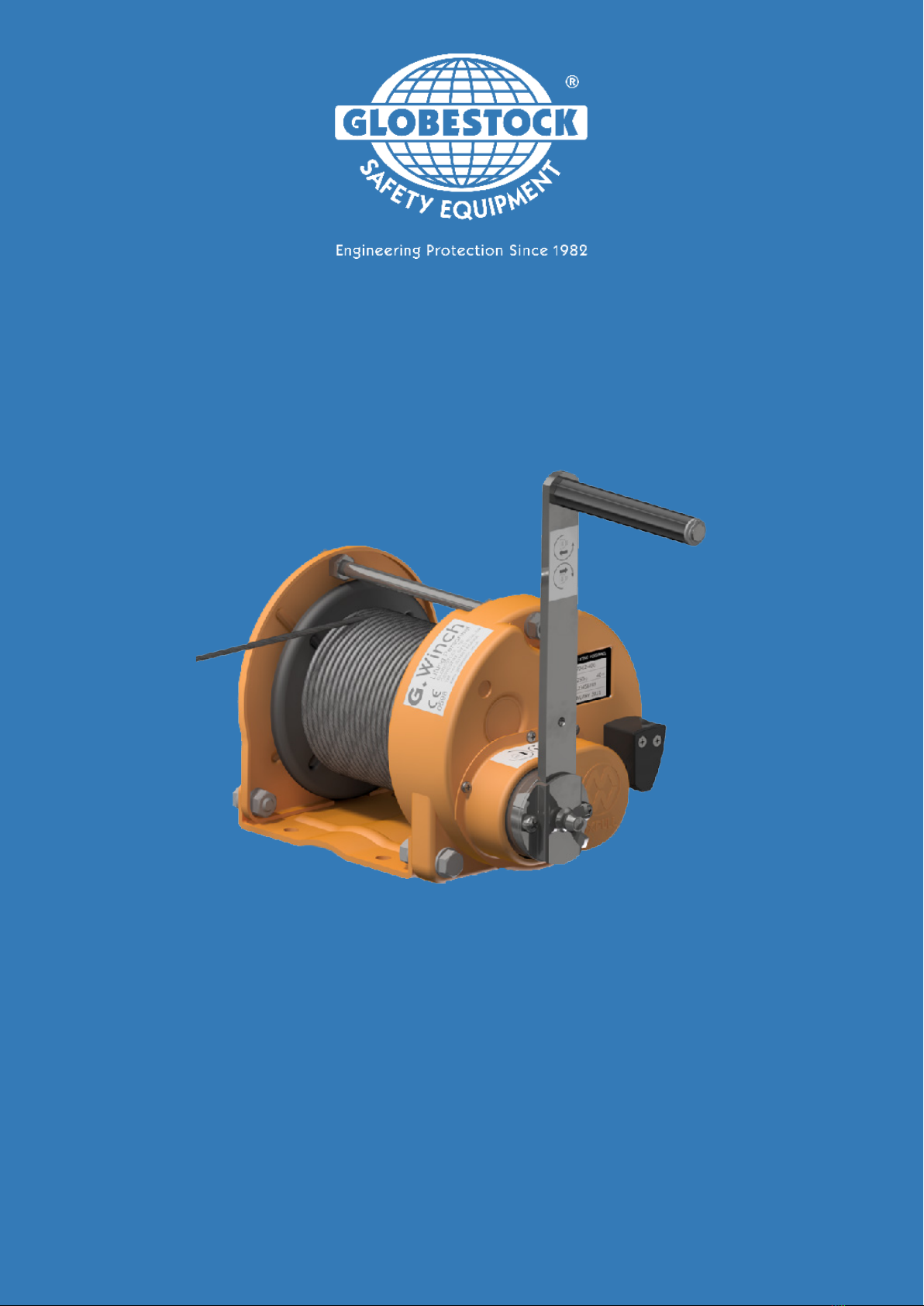
3. INSPECT ROPE & KARABINER
To extract the rope, the pawl mechanism must be disengaged and
held to allow the drum to free spool. This can be clamped into
place, or the pawl stop can be removed, and the pawl lever pushed
beyond the return point.
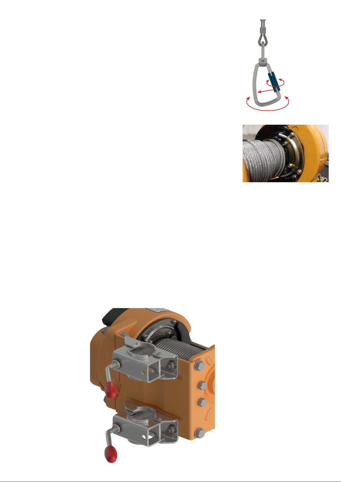
Ifthepawlstopisremoved,thismustbere-ttedbefore
completion.
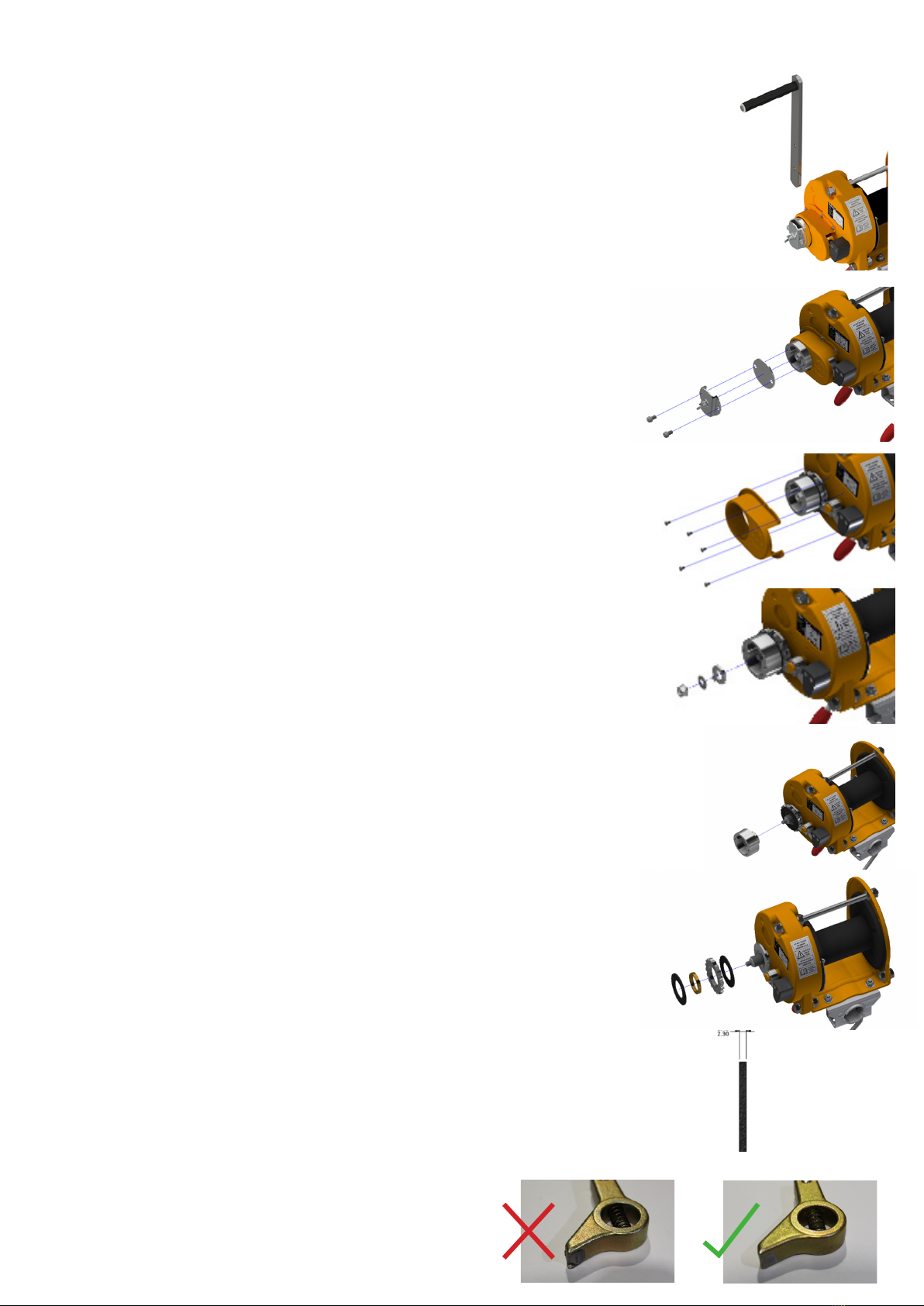
Fully extract the wire rope inspecting for:
Corrosion Broken Wires Kinking Severe Wear Damaged Fittings

5
Inspect the karabiner making sure there are no signs of damage or
corrosion. The swivel function must rotate smoothly, and the gate
opens and closes without interference.
If the rope is to be replaced, remove the 4 screws from the rope
retaining plate and uncoil the rope from the drum. A new rope can be
ttedatreassembly.
4. INSPECT DRUM CONDITION
The drum must rotate freely, causing no interference with the winding
actionoftherope.Ifthedrumisdiculttorotate/hastightspots
when rotating please refer to step 1 of reassembly
5. INSPECT BRACKETS (IF PRESENT)
Checkbracketstoensureallitemsarepresentandttedcorrectly.
Check all items are free from damage, corrosion, are in good working
order and function correctly. (Pay particular attention to the clamp
body lever thread location into the clamp body).

6
6. REMOVE AND INSPECT CLUTCH
COMPONENTS AND BRAKE LININGS
6.1 Remove the winch winding arm and check for damage and good
location into the handle holder. Ensure the wing screw is not
damaged and locks the winch arm in place when tightened.
6.2 Remove the 2 screws, handle holder and clutch shield plate.
6.3 Remove the 5 clutch cover screws and clutch cover. Inspect for
damage.
6.4 Remove the centre nut, washers and dodecagon washer.
6.5 Unscrew the clutch body. (If this is excessively tight and cannot
bedonebyhand,retthehandleholderscrewsandapplyleverage
between the two points to rotate)
6.6 Remove the ratchet gear, centre bush and brake linings.
6.7 Inspect the brake lining thickness using a set of digital calipers.
Refer to table [X] on page [X] for minimum tolerance.
6.8 Inspect pawl tip for excessive wear and replace if necessary.

7
Reassembly
Ensure all damaged / failed components are replaced at
reassembly.
7. REPLACE PAWL (IF NECESSARY, OTHERWISE
SKIP TO STEP 8)
Using a set of circlip pliers, remove the pawl retaining circlip and
washer.Thepawlcanthenbeliftedothedowelpin.(Keep
coveredtopreventthespring-loadedballbearingfromringo)
Totthenewpawl,pushtheballbearingintothecavityofthelever
armandholdinplacewhilstpositioningontothedowel.Retthe
washer and circlip.
8. REPAIR ROPE DRUM ALLIGNMENT (IF
NECESSARY, OTHERWISE SKIP TO STEP 9)
8.1 Remove the 2 case retaining screws and the external nut of
the stay bolt. (Do not adjust any other nuts on the stay bolt as this
willaectthecasealignment)
8.2LiftthecaseothebodyoftheG.Winch,exposingtheinternal
components.
8.3 Using a soft mallet, tap the welded gear down back into
position so that the drum can rotate freely.
8.4Retthecase,ensuringtoalignall3sleevesbackinto
position.
8.5 Fasten down the case screws and the stay bolt nut securely.

8
9. REFIT CLUTCH ASSEMBLY
9.1 Ensure the base plate is correctly seated.
9.2 Clean down both brake linings with a dry cloth and apply a very
small amount of lithium-based grease to both surfaces (Ensure not
to apply too much grease as this will cause the brake to slip when
under load)
9.3Placetherstliningontothebaseplate.
9.4 Place the gear ring onto the lining, ensuring the correctly
orientation as shown.
9.5 Fit the brass ring into the centre of the gear ring.
9.6 Place the second lining onto the gear ring.
9.7 Apply a small amount of lithium-based grease to the thread of the
clutch body and screw down onto the brake lining. (Ensure all
components are lined up and the clutch body does not pinch any of
the brake linings)

9
9.8Retthedodecagonwasherandstandardwasherensuringthe
correct position of the washer tongue.
9.9Retthespringwasherandnutandfastendowntight.(To
achieve this, the handle holder screws can be inserted into the clutch
body and used as leverage, as shown)
10. FIT ROPE KIT (IF THE ROPE KIT IS NOT BEING
REPLACED, SKIP TO STEP 11)
Feed the rope through the 2 holes in the rope drum and neatly wrap
around the drum towards the locking plate.
Keeptheropetightfor6rotationswhentting5mmropeand5
rotationswhentting6mmrope.
Secure the rope using the plate ensuring the end stop is seated inside
the groove of the rope drum and does not protrude into the path of the
rope.
11. WIND THE ROPE ONTO THE DRUM
Using a 17 mm socket and drill adapter, wind the drum via the nut
in the clutch body. Keep the pawl stop in free spool position to prevent
excessive wear on the tip and neatly lay the rope until fully wound.
Retain the rope in position by clipping the safety hook to the stay bolt.
12.REFIT THE CLUTCH SHIELD PLATE,HANDLE
HOLDER AND WINCH ARM

13. LABEL POSITONS
Apply the new labels in the positions shown.
Raise- lower label (070-08)
G.Winch label (070-12)
G.Winch identity label (070-11)
Warning label (070-09)

10
Testing
13. STATIC LOAD TEST
The G.Winch must be subjected to a static load test every 12
months. Each model must be tested to 1.5 times the maximum
working load for 15 seconds:
MounttheG.WinchtoaG.Tripodonthetestingxtureandfeed
the rope over the pulley and clip to the load cell.
Lay the rope across the drum to prevent the rope from crushing
and bedding in during the test.
Turn the winding arm clockwise, tightening the rope and
applying load to the G.Winch. Once the correct load has been
achieved this must be held for 15 seconds with no signs of
slippage and then released.
Neatly wind the rope back onto the drum ensuring the winch
functions correctly.
Model Test Load (kg)
GSE070-136 204
GSE070-150 225
GSE070-200 300
GSE070-250 375

11

GLOBSTOCK ENGINEERING LTD Issue: 003
Date: 10-04-2021
G.WINCH BRAKE DISC DETAILS NOTICE
DUE TO A CHANGE IN SIZE OF THE BRAKE PADS PLEASE
CONSIDER THE DIMENSIONS UPON REPLACEMENT
CONCERNING SERIAL
NUMBER 467500
BRAKE PAD DETAILS
PART No MINIMUM THICKNESS
BEFORE REPLACEMENT
BUILT BEFORE 467500
(2006)
070-21 2.3 mm
BUILT AFTER 467500
(2006)
070-21A 2.45 mm

No
Description
Qty
1-A
Gear Case
1
2-A
Gear Case Cover
1
3
Bed Plate
1
4-A
Side Frame
1
5
Drum
1
6
070-006 Rope Grip
1
8-B
Hex Button Head Screw
4
10
Clutch Cover
1
11-B
Drum Shaft Main Gear
1
1
1
1
1
1
1
1
1
1
12 Shaft Distance Piece
13 Spur Gear Pinion
14 Clutch Pinion
15 Shaft Washer A
16 Shaft Washer B
17 070-17W Brass Ring
18 Ratchet Gear
19 070-19BP Base Plate
20 Clutch
21 070-21ABrake Lining
2
22
070-22 Dodecagon Washer
1
23
070-23-24-54 Stopper
1
25
070-25 Handle Holder
1
26
070-26 Clutch Shield Plate
1
27-A
070-06 Handle Assembly
1
28
070-06 Handle Assembly
1
29
070-06 Handle Assembly
1
30
070-06 Handle Assembly
1
31
070-31 Stay Bolt
1
32-B
Bolt M12 x 50
2
36-A
Bolt M10 x 16
2
38-A
Bolt M10 x 16
2
40
Bolt M12 x 25
2
43
070-43 Cover Screw
7
44-A
Spacer
1
44-B
Spacer
2
45
Parallel Pin
1
46
Washer
1
47-A
Hexagon Nut
1
50
070-50 Washer for Pin
1
51
070-51 Circlip
1
56
070-56 Washer and Screw
2
58-B
Bearing
1
59-B
Bearing
3
60-A
Bearing
1
61
Circlip
1
Parts listed in blue available as spares

Globestock Ltd. reserve the right to change specications without prior notice.
All information herein is copyright protected by Globestock Ltd. 2021.
The Globestock logo and name is a registered trademark of Globestock Ltd.
Other manuals for G.Winch
1
Table of contents
Other Globestock Winch manuals
Popular Winch manuals by other brands

Ingersoll-Rand
Ingersoll-Rand Force 5 Parts, operation and maintenance manual

Ramsey Winch
Ramsey Winch RPH 8000 Operating, Service and Maintenance Manual

Wahlberg
Wahlberg Winch 25 user manual

Wahlberg
Wahlberg 50 Series user manual

Sealey
Sealey GWE1200.V2 instructions

Comeup
Comeup Seal Gen2 16.5s quick start guide

haacon
haacon 220.0.3 operating instructions

Comeup
Comeup CWS-230 manual

Harken
Harken Performa Winch 40.2 PTP Installation and maintenance manual

Warrior Winches
Warrior Winches T1000 owner's manual

Smittybilt
Smittybilt XRC 3.0 installation instructions

Ingersoll-Rand
Ingersoll-Rand Liftstar LS2-600H Product information