6
Boiler Design
Boiler Design
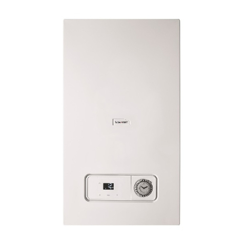
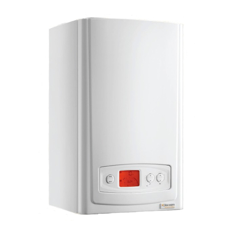
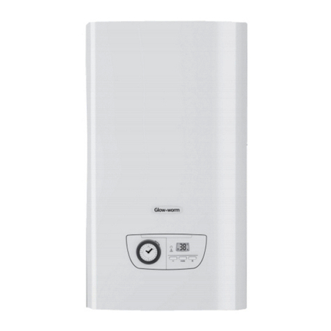
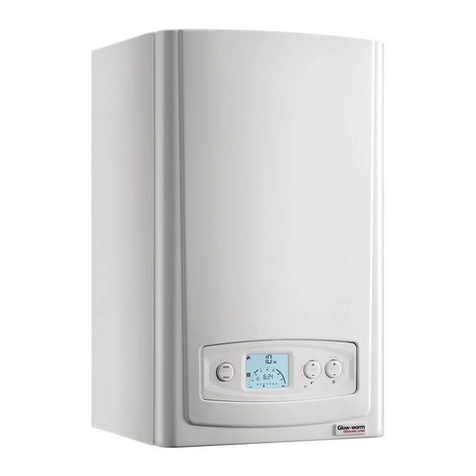
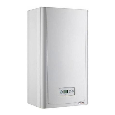
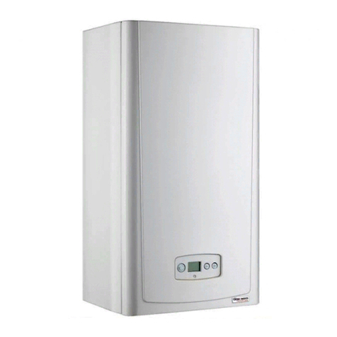
This boiler is designed to provide central heating and
instantaneous hot water for use as part of a sealed water central
heating system with fully pumped circulation.
The pumps , expansion vessel and associated safety devices are
all tted within the boiler. The integral programmer is designed for
both simple operation and maximum control. Once the controls
are set the boiler will operate automatically.
Glow-worm has specially designed accessories for your appliance
depending on yourrequirements, please contact your supplier
or visit our website www.glow-worm.co.uk.
Condensate Drain
A plastic drain pipe must be tted to allow discharge of condensate
to a drain.
Condensate should, if possible, be discharged into the internal
household draining system. If this is not practical, discharge
can be made externally into the household drainage system or
a purpose designed soak away, see section 9 for more details
Pluming from ue terminal
Like all condensing boilers this appliance will produce a plume
of condensation from the ue terminal in cool weather. This is
due to the high efciency and hence low ue gas temperature
of the boiler.
This is normal and not an indication of a fault.
Maintenance and Servicing
To ensure the continued efcient and safe operation of the
appliance it is recommended that it is checked and serviced as
necessary at regular intervals. The frequency of servicing will
depend upon the particular installation conditions and usage.
If this appliance is installed in a rented property there is a duty of
care imposed on the owner of the property by the current issue of
the Gas Safety (Installation and Use) Regulations, Section 35.
Servicing/maintenance should be carried out by a competent
person approved at the time by the Health and Safety Executive
in accordance with the rules in force in the countries of destination.
To obtain service, please call your installer or Glow-worm’s own
service organisation using the telephone number on the inside
front cover of this literature.
Please be advised that the ‘Benchmark’ logbook should
be completed by the installation engineer on completion of
commissioning and servicing.
Spare Parts
Remember, when replacing a part on this appliance, use only
spare parts that you can be assured conform to the safety
and performance specication that we require. Do not use
reconditioned or copy parts that have not been clearly authorised
by Glow-worm.
If a part is required contact Glow-worm’s own service organisation
using the telephone number on the inside front cover of this
booklet.
Please quote the name of the appliance, this infomation will be
on the name badge on the front of the appliance.
If in doubt seek advice from the local gas company or Glow-
worm’s own service organisation using the telephone number
on the inside front cover of this booklet.
Servicing, Maintenance and Spare Parts
Electrical Supply Failure Reset Switch
In the event of a power supply failure the boiler will not work.
Normal operation of the boiler should resume when the electrical
supply is restored.
However, if the boiler does not resume normal operation turn
the mains reset switch off and on. If the boiler does not resume
normal operation after this operation the overheat stat may have
operated.
Overheating safety
In the event of the boiler overheating the safety devices will
cause a safety shutdown. If this happens, call your Installation/
Servicing company.
Discharge and Relief Valves
Heating and Domestic discharge safety valves and a
Domestic hot water pressure relief valve are tted to this
appliance. The valves must not be touched except by a
competant person.
If the valves discharges at any time, switch the appliance off
and isolate it from the electrical supply.
Frost protection
The appliance has a built in frost protection device that protects
the boiler from freezing. With the gas and electric supplies ON and
irrespective of any room thermostat setting, the frost protection
device will operate the pump when the temperature of the boiler
water falls below 7°C.
The burner will re if the temperature inside the boiler falls to 3°C.
When the temperature reaches 10°C the boiler stops.
Any other exposed areas of the system should be protected by
a separate frost thermostat.
Condensate Drain Blockage
As a safety feature the boiler will stop working if the condensate
drain becomes blocked. During freezing conditions this may be
due to the forming of ice in the condense drain external to the
house. Release an ice blockage by the use of warm cloths on
the pipe. The boiler should then restart. Contact your installation/
servicing company if the fault persists.
Safety Devices
