GME G-Fish G142FD User manual

INSTRUCTION MANUAL
G142FD FISHFINDER
www.gme.net.au

PAGE 2 INSTRUCTION MANUAL G•FISH–G142FD

G•FISH–G142FD INSTRUCTION MANUAL PAGE 3
Please read through this manual before the first
operation. If you have any questions, please contact the
customer service or your local dealer or distributor.
Extensive exposure to heat may result in damage to the
fishfinder.
Connection to the power source with reversed polarity
will damage the fishfinder severely. This damage is not
covered by the warranty.
Do not disassemble. The fishfinder contains dangerous
high voltage circuits which only experienced technicians
must handle.
Exposure of the display to UV rays may shorten the life
of the liquid crystals used in you plotter. This limitation is
due to the current technology of the LCD display.
Avoid overheating which may cause loss of contrast and,
in extreme case, a darkening of the screen. Problems
which occur from over heating are reversible when
temperature decreases.
Important
It is the owner’s sole responsibility to install and use the unit
in a manner that will not cause accidents, personal injury or
property damage. The user of this product is solely responsible
for observing safe boating practices.
Global Positioning System: The Global Positioning System
(GPS) is operated by the US government which is solely
responsible for its operation, accuracy and maintenance.
The GPS system is subject to changes which could affect the
accuracy and performance of all GPS equipment anywhere in
the world.
Installation: If installation is not correct, the unit can not
perform at its designed potential. If in doubt, consult your
GME dealer. Ensure that any holes made are in a safe position
and will not weaken the boat’s structure. If in doubt, consult a
qualified boat builder.
GME DISCLAIMS ALL LIABILITY FOR ANY USE OF THIS
PRODUCT IN A WAY THAT MAY CAUSE ACCIDENTS,
DAMAGE OR THAT MAY VIOLATE THE LAW.
Governing language: This statement, any instruction
manuals, user guides and other information relating to the
product (documentation) may be translated to, or has been
translated from, another language (translation). In the event
of any conflict between any translations of the documentation,
the English language version of the documentation will be the
official version of the documentation. This manual represents
the installation procedures as at the time of printing. GME
reserves the right to make changes to specifications without
notice.
Copyright © 2010 GME, Australia, all rights reserved.
Presentation
Thank you for having purchased a GME product. This
handbook contains an explanation of how to install, operate
and maintain your unit.
SAFET Y INSTRUCTIONS
If you require technical advice or assistance, contact your
nearest GME dealer or visit our website, www.gme.net.au.
Screen Cleaning Precautions
Use a tissue or lens cloth and a cleaning spray containing
Isopropanol (a normal spray cleaner sold for PC screens).
Fold the tissue or lens cloth into a triangular shape,
moisten the tip and use the index finger behind a corner
to move the tissue across the surface in overlapping side
to side strokes. If the tissue is too wet, a noticeable wet
film will be left in its path and you will need to repeat
the process. If too dry, the tissue won’t glide easily, and
may damage the surface.

PAGE 4 INSTRUCTION MANUAL G•FISH–G142FD
1 - Introduction
1-1 General Information ............................5
1-2 Packing List ...................................5
1-3 Specifications .................................5
1-4 Optional Accessories . . . . . . . . . . . . . . . . . . . . . . . . . . .6
2- Getting Started
2-1 Mounting the Unit .............................6
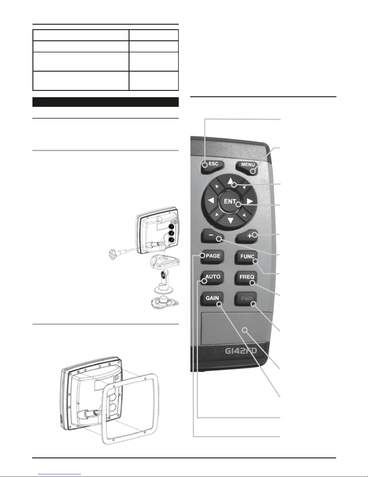
2-1-1 Bracket Mounting ............................6
2-1-2 Flush Mounting ..............................6
2-2 Keys ........................................6
2-3 Secure Digital (SD) Card . . . . . . . . . . . . . . . . . . . . . . . . .7
2-4 Simulation Mode ...............................7
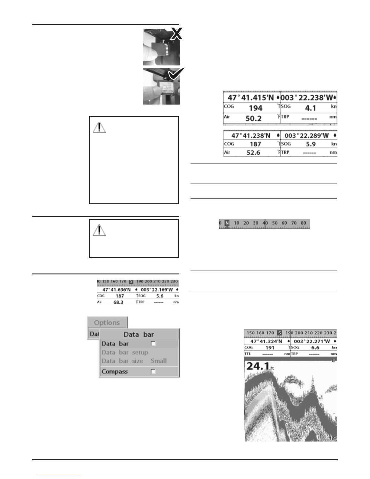
2-5 Data Bar .....................................7
2-6 Compass .....................................7
2-7 Multi window displays. . . . . . . . . . . . . . . . . . . . . . . . . . .7
3 - General Operation
3-1 Manual / Auto Power on and off . . . . . . . . . . . . . . . . . . .8
3-2 Brightness, night mode and Background . . . . . . . . . . . . .9
3-3 The page window ..............................9
3-4 Sonar ......................................10
3-4-1 Interpreting the display . . . . . . . . . . . . . . . . . . . . . . .10
3-4-2 Mode ....................................10
3-4-3 Single and Dual frequency fish finding . . . . . . . . . . . .10
3-4-4 Range ....................................10
3-4-5 Gain .....................................11
3-4-6 Sonar window display . . . . . . . . . . . . . . . . . . . . . . . .11
3-4-7 No split ...................................11
3-4-8 Split zoom and Full Screen zoom . . . . . . . . . . . . . . . .12
3-4-9 Split bottom. . . . . . . . . . . . . . . . . . . . . . . . . . . . . . . .12
3-4-10 Split 50/200 ..............................12
3-4-11 Split A-Scope ..............................12
3-5 Gauges .....................................12
3-6 AIS ........................................13
3-6-1 AIS Windows ...............................13
3-7 DSC .......................................14
3-7-1 Distress ...................................14
3-7-2 Poll ......................................14
3-8 NAVTEX ....................................14
3-9 Engine Faults ................................15
4 - Advance Settings
4-1 System Configuration Settings . . . . . . . . . . . . . . . . . . . .15
4-1-1 Language .................................15
4-1-2 Beep volume ...............................15
4-1-3 Auto power ................................15
4-1-4 Features ..................................15
4-1-5 Factory reset ...............................15
4-1-6 About ....................................15
4-2 Sonar Settings ................................15
4-2-1 Frequency .................................15
4-2-2 Palette ....................................15
4-2-3 Scroll speed ................................15
4-2-4 Digit size ..................................16
4-2-5 Fish ......................................16
4-2-6 Advance Settings ............................16
4-2-7 Restore default .............................16
4-3 Memory Settings ..............................16
4-3-1 Screen snap shot ............................16
4-4 AIS Settings .................................16
4-4-1 Alarm option ...............................16
4-4-2 Restore default .............................16
4-5 Alarms .....................................16
4-5-1 Fish ......................................17
4-5-2 Deep .....................................17
4-5-3 Shallow ...................................17
4-5-4 Temperature ...............................17
4-5-5 Temperature rate ............................17
4-5-6 Low battery ................................17
4-5-7 AIS ......................................17
4-5-8 Restore default .............................17
4-6 Others .....................................17
4-6-1 Simulate ..................................17
4-6-2 GPS ......................................17
4-6-3 Units .....................................17
4-6-4 Comms ...................................17
4-6-5 Calibrate ..................................17
4-6-6 Time .....................................18
4-6-7 Restore default .............................18
5 - Installation
5-1 Options and Accessories . . . . . . . . . . . . . . . . . . . . . . . .18
5-2 Connections .................................18
5-3 Power/data cable .............................19
5-4 Alarm ......................................19
5-5 GPS antenna .................................19
5-6 NMEA 0183 .................................20
5-7 NMEA 2000 .................................20
5-8 Sonar Transducers .............................21
5-9 Setup and test ...............................21
Warranty .......................................22
CONTENTS

G•FISH–G142FD INSTRUCTION MANUAL PAGE 5
1 - INTRODUCTION
1-1 General Information
Fishfinders use an echo-sounding technology which uses a
transducer to send ultrasonic sound waves through water.
The sound waves are reflected back the transducer when they
strike an object such as the bottom.
1-2 Packing List
Item Part number
Display G142FD
Bracket MB029
Display Cover CVR031
Power Cable LE031
Bracket mounting screw MK006
Flush mount Kit with screws MK005
User’s Manual 310503
Cable tie MK007
P58 Transducer TD003
1-3 Specifications
Category Detail
GENERAL
Size 164 mm(H) x 183 mm(W) x 74 mm(D)
Display 142 mm (5.6”) diagonal, TFT colour, 480
x 640 pixels.
Brightness 10 Steps
Power
Consumption
Under 12 W
Supply
voltage
10 to 34 V DC
Supply current 13.8 V, 800mA min - no backlighting.
1000mA max - full backlighting.
External
beeper or
light output
Switched to ground to sound alarm, 30 V
DC, 200 mA maximum
Operating
temperature
-10° to 50°C
ALARMS
User set: Too shallow, too deep, fish, temperature, low
battery, dangerous AIS vessels.
COMMUNICATIONS
NMEA NMEA 0183 4800, 9600, 38400 baud,
NMEA 2000
NMEA 0183
Inputs from
compatible
instruments
DBK, DBS, DBT, DPT, GGA, GLL, GNS,
GGA, GSV, HDG, HDT, MDA, MTA, MTW,
MWD, MWV, RMC, RPM, VHW, VTG,
VWT, ZDA.
NMEA 2000
Inputs from
compatible
instruments
System date and time (PGN126992),
Vessel Heading (PGN127250), Engine
parameters/Rapid Update (PGN127488),
Engine parameters/Dynamic
(PGN127489), Trip parameters/Engine
(PGN127497), Engine parameters/Static
(PGN127498), Fluid level (PGN127505),
Water Speed (PGN128259), Water depth
(PGN128267), Position/Rapid Update
(PGN129025), COG & SOG/Rapid Update
(PGN129026), GNSS Position Data
(PGN129029),GNSS DOPs (PGN129539),
GNSS Sats in View (PGN129540), Wind
Data (PGN130306), Environmental
Parameter-Water temp (PGN130310),
Environmental Parameter (PGN130311).
NMEA 0183
Outputs, for
compatible
instruments
APA, APB, BWR, GGA, GLL, GSA, GSV, RMB,
RMC, VTG, XTE, DBT, DPT, MTW, VHW, XDR.
NMEA 2000
Outputs, for
compatible
instruments
Water Speed (128259), Water depth (128267),
XTE (129283), NAV. data (129284), NAV. data
(129285), COG & SOG (129026), GNSS position
(129029), Water temp.(130310).
SONAR FISHFINDING
Depth range Min : 0 m ~ 5 m, Max : 0 m ~ 1500 m
Sonar output Power: Variable, up to 600 W RMS
Dual frequency: 50 kHz and 200 kHz.
Temperature Range 0° to 37.7°C (32°F to 99.9°F) Resolution
of 0.1° unit.
Speed (from
paddlewheel
transducer)
1 to 96.6 kph (57.5 mph, 50 kn).
AUTO gain ON/OFF
Zoom Function OFF/Auto zoom/Manual zoom/Seabed fixation
zooming unit
A-Mode ON/OFF
Demo ON/OFF
Battery Voltage
Display
Display the voltage
Colour 16 Colour
Scroll speed 4 steps and stop
Threshold
function
0% ~ 75%

PAGE 6 INSTRUCTION MANUAL G•FISH–G142FD
1-4 Optional Accessories
Item Part Number
Y-Cable LE0332
B45 Transducer
Bronze Thru-Hull 600 W, 200/50 kHz
TD002
P79 Transducer
In-Hull 600 W, 200/50 kHz
TD001
GETTING STARTED
2-1 Mounting the Unit
G142FD is supplied with bracket and flush mount Kit. You can
choose a method of installation according to your preference.
2-1-1 Bracket Mounting
Before installing ensure the area the bracket is mounted to is
strong enough to support the weight of the fishfinder. After the
location is found, attach the mounting base to the area using
the supplied hardware.
Mounting the display Unit:
1 Hold the display unit and find mounting
groove on back of display.
2 Gently push the display unit into the
bracket ensuring groove on back of
display slides into bracket.
3 Turn knob clockwise to lock.
Removing the display unit:
1 Turn the unit off.
2 Turn the knob to counter clockwise.
3 Pull the display unit out.
4 Carefully remove all cables.
2-1-2 Flush Mounting
1 Find a suitable location for flush mounting and tape flush
mounting template to location.
2 Drill a hole in the area of the cutout.
3 Cut out the area with a jig saw.
4 Drill four holes as marked for mounting studs.
5 Install the mounting studs on the fishfinder and insert them
into the mounting holes.
6 Attach the fishfinder to the mounting location by attaching
the supplied hardware to the mounting studs.
2-2 Keys
ESC Exit from menu
and return to
previous menu.
MENU Access to
settings menu - Shows
available options of
the current window.
CURSOR Use to
review sonar history.
ENT Selects the
desired option or to
confirm selection.
+ Increases water
depth range.
- Decrease water
depth range.
FUNC Screen
snapshot.
FREQ Selects a
frequency between
50 kHz or 200 kHz or
mixed.
POWER Turns power
on/off. Open display
brightness and night
mode.
SD Card Open the
cover to install an
SD card.
GAIN Displays the
gain menu.
AUTO Sets gain and
range to automatic.
PAGE Sets a screen
you want to display.

G•FISH–G142FD INSTRUCTION MANUAL PAGE 7
2-3 Secure Digital (SD) Card
This section provides instructions for inserting
and removing SD card Procedure
Inserting the SD Card:
1 Hold the SD card so that you can see
the label.
2 Open the door, gently push the SD card
into the slot; push the SD card in until you
hear a click sound, close the door.
Removing the SD Card:
1 Turn off the unit.
2 Open the door
and push in on the
SD card until it is
released.
3 Close the door.
2-4 Simulation Mode
Simulation mode is
good for practicing to
use of the unit
2-5 Data Bar
Data bar displays useful
navigation information at
the top of the display.
Displaying Data Bar:
1 Press MENU and
select Data bar.
2 Select Data bar.
Setting the data displayed in Data bar
1 Press MENU and select Data bar.
2 Select Data bar then Data bar setup.
3 Move the cursor key to highlight the data field you want to
change then press ENT.
4 Select Data type.
5 Select a desired data you want to display in the field then
press ENT.
6 Repeat above steps if necessary.
Selecting the Data bar size
1 Press MENU and select Data bar.
2 Select Data bar then Data bar size.
3 Select the desired size of data bar.
Large
Small
Tip: Even though you set up a data bar for a specific window,
the data bar does not apply to the other window
2-6 Compass
The fishfinder computes compass direction from the
constellation of GPS satellites and it is displayed at the top of
the screen.
When the compass is displayed, COG is always displayed in
the data field.
Note: If no GPS is connected, the compass heading will not be
accurate.
Tip: COG (Course Over Ground) – The course your vessel
is heading.
To turn the compass off or on:
1 Press MENU and select Data bar.
2 Select Compass.
While the simulation mode
is turned on, the fishfinder
does not receive any data
from the transducer.
Insert SD card correctly (Do
not force).
Close SD card door firmly all
the times.
Do not remove the SD card
during reading and writing.
Max memory size of SD card
is: Standard SD 1 GB
SDHC 4 GB

PAGE 8 INSTRUCTION MANUAL G•FISH–G142FD
2-7 Multi window displays
Adding a window
1 Press PAGE and select the Add icon.
2 Select an icon you want to add.
Changing the window size:
1 Press PAGE and select the Split icon on
bottom and press ENT key.
2 Press or to change the height of the
windows if there is only two windows.
3 Press ESC key.
Deleting a window:
1 Press and hold PAGE to select a window you want to
delete.
2 Press PAGE and select the Remove icon to remove.
3 Press ENT key.
Replacing two windows on the display
1 Press and hold PAGE to active desired window you want
to replace.
2 Press PAGE, select the Replace icon.
3 Select icon you want to display then press. ENT
The active window
To distinguish an active window among windows, a border
indicates the active window. To change the active window to
the next window, press and hold PAGE.
Favourite displays
The most commonly used windows are called favourite
displays and up to six favourite windows can be saved. Also
each favourite display can have data bar and compass.
Displaying a favourite display:
1 Press PAGE twice.
2 When the favorite window, pops up, select a display.
Adding a
favourite
display
1 Organize a window
as you want.
2 Press PAGE to
show the main
window.
3 Select the Save icon at the bottom
4 Select an icon where you want to add your favourite display.
If you add the new favourite display on existing favourite
display new display will overwrite the old display.
3 - GENERAL OPERATION
3-1 Manual / Auto Power on and off
Manual power on
Press PWR and hold until the display shows the start up page.
When the Warning screen appears, press ENT to accept.
Manual power off
Press PWR and hold for 5 seconds. A counter timer appears
on the screen. If you release the button before the countdown
timer reaches zero, the fishfinder will stay On.
Auto power – If the unit is wired for auto then:
• The unit turns on automatically when you turn on the
boat’s ignition.
• You can not turn off the unit if the ignition is turned on.
• If Auto power off is set, the unit turns off automatically
when you turn off the boat’s ignition.
• If Auto power off is set, the unit will not be turned off even
though the boat’s ignition is turned off. To turn off, you
need to turn off the unit manually.

G•FISH–G142FD INSTRUCTION MANUAL PAGE 9
You can change the screen setting for the display. To change
settings, momentarily press PWR.
Brightness
To change the brightness, select Brightness, and press to
dim or to brighten.
Press ESC to return to the previous screen.
Night mode
The fishfinder has preprogrammed settings allowing you to
customise the look of the fishfinder. The default is
daytime view.
To change mode:
1 Highlight Night
mode
2 Press or ENT.
Background
You can Change the background colour if necessary. This
selection is a personal preference. Select the option that gives
you the clearest view for your weather conditions and
viewing angle.
Press PAGE to show the page window and select a function
icon you want to display.
Note: Some function icons require optional units and
connected sensors. If you press PAGE one more time in the
main window, the favourite window is displayed.
3-2 Brightness, night mode and Background
3-3 The page window

PAGE 10 INSTRUCTION MANUAL G•FISH–G142FD
3-4 Sonar
The G142FD has a sonar function when the unit is connected
to a depth transducer.
3-4-1 Interpreting the display
Single fish: Fish symbols with depth.
Bottom: Hard bottoms such as rock and coral shown as wide
bands. Soft bottoms such as mud, weed and sand show as
narrow bands.
Depth range: Depth range of display.
The window scrolls from right (recent sonar record) to left (old
sonar record).
3-4-2 Mode
The unit operates in two different modes. You can choose a
mode depending on the conditions.
• Auto mode: This is the most commonly used option. In
this mode, settings are automatically adjusted for the best
display of fish and bottom according to the environment.
• Manual mode: Use this option for manual settings. This
option might bring you better results for the conditions.
To change a mode;
1 Press MENU then
select Gain.
2 Select Mode then
Manual or Auto
and press ENT.
3 Press ESC to exit.
3-4-3 Single and Dual frequency fish finding
Sonar frequencies
The G142FD is a dual frequency unit using both 200 kHz and
50 kHz to detect various bottom conditions at various depths.
To select the sonar frequency in sonar window:
1 Press MENU, select Frequency.
2 Select Frequency and press ENT.
3 Press ESC to exit.
High frequency (200 kHz )
The higher ultrasonic signal, the better the resolution. For this
reason the 200 kHz frequency is ideal for detailed observation
of fish schools.
Low frequency (50 kHz)
The lower frequency signal is a wider signal for a wider
detection area. Therefore, the 50 kHz frequency is useful for
general detection and judging bottom conditions.
Mixed frequencies (200 kHz / 50 kHz)
The Mixed frequency combines the 200 kHz and the 50 kHz in
the Sonar window.
Note: the 50 kHz signal will travel deeper than the
200 kHz signal.
The display is useful
for comparing the
same picture with two
different frequencies.
3-4-4 Range
Range is the depth of water displayed on the sonar window.
The basic range may be chosen in either Auto or manual mode.
Auto: When the mode is set to Auto, the unit adjusts the
depth automatically for the best performance. This option is
recommended for normal operation.
Manual: When the mode is set to Manual, the unit only
displays the depth of water at a chosen range. This could mean
that the sea bed is not displayed as it is out of range, as shown
on the following page.
Depth
Single fish
School of fish
Depth line
Bottom
Depth range
Colour bar
High Frequency (200 kHz)
Low Frequency (50 kHz)

G•FISH–G142FD INSTRUCTION MANUAL PAGE 11
To set the manual mode in the sonar window:
1 Press MENU, select Range.
2 Select a mode you want and press ENT.
3 If you select the manual mode, press + or – to change the
value of the max displayed depth.
3-4-5 Gain
The gain menu
The gain is the amount of signal strength received from the
transducer and the threshold is the level of ultrasonic signal
that is ignored by a set value.
When you use the manual mode and threshold, the values of
gain and threshold need to be set very carefully.
In the Gain window, you can set the
gain and threshold.
To change a value:
1 Press MENU, select Gain or press
gain button.
2 Select a mode.
3 If you select a Manual mode, adjust each frequency gain
value by pressing or . If you select the Auto mode,
it will be changed to manual mode if you change the
frequency value.
3-4-6 Sonar window display
Five sonar display windows are available and each display
window has unique characteristics. Select a display window
depending on your needs. The default display is No split.
To change a Sonar display window in the sonar
window:
1 Press MENU, select Window mode.
2 Select the desired sonar display.
No split: Displays Sonar history at a given frequency
(50 or 200 kHz), (see section 3-4-7).
Split zoom: This mode expands a chosen area of the normal
picture in full vertical size on the left-hand side of the window.
Full screen zoom: Displays a zoomed section on full screen
(see section 3-4-8).
Split bottom: Displays Sonar history and a bottom trace
focus in a zoomed section (see section 3-4-9)
Split 50/200: Displays the 50 kHz sonar history on the
left and the 200 kHz sonar history on the right. This display
is useful for comparing the same history with two different
frequencies. (see section 3-4-10).
Split A-Scope: Display Sonar history and echo strength (see
section 3-4-11).
You can change the split
ratio if the window is split.
1 Press MENU and select
Window split.
2 Press or to adjust
the ratio.
3 Press ENT.
3-4-7 No split
No split window displays a sonar history at a given frequency
(50 or 200 kHz)
Low Frequency (50 kHz)
The 50 kHz frequency is ideal for detecting the wider area
which means low frequency is useful for general detection
and judging bottom condition. This frequency is also good for
deeper water.
High Frequency (200 kHz)
The 200 kHz frequency will provide a better resolution which
means it is ideal for the observation of fish or fish schools. This
frequency is also good for shallow water.
To set a frequency for this display:
1 Press MENU.
2 Select Frequency.
3 Select a desired
frequency.
You can also review
old sonar records, press
and to review
the history. To return to
current scanning,
press ESC .
When the set depth
is too low
When the set depth
is too high

PAGE 12 INSTRUCTION MANUAL G•FISH–G142FD
3-4-8 Split zoom and Full Screen zoom
Split zoom:
Split zoom mode expands selected area of the single frequency
by VRM (Variable Range Mark). The left side displays zoomed
section of current sonar record. The VRM of right side indicates
the zoom section area.
• Press or to change
the zoom range.
• Press + or – to change
the depth range.
Bottom lock
If Bottom lock is on, the
zoom depth (the depth of
the zoom section) is adjusted
automatically so that the
bottom is always displayed in
the zoom section.
• To turn Bottom lock on or off press MENU.
Full Screen zoom
Select Full Screen Zoom, highlight bottom lock and press ENT.
Full screen zoom displays only the zoom section of split zoom.
3-4-9 Split bottom
Split bottom display provides a normal picture on the right
half and a selectable range over and below the bottom line is
expanded onto the left half of
the screen. This mode is useful
for detecting bottom fishes.
• Use the or keys to
adjust the zoom range.
• Press + or – to change
the range
• The VRM moves up
and down to calculate
the bottom depth
automatically.
3-4-10 Split 50/200
The 50 kHz display
appears on the left and
the 200 kHz appears
on the right. This dual
frequency display is very
useful for comparing the
same scanning with two
different frequencies.
3-4-11 Split A-Scope
This display shows echoes at each transmission with
amplitudes and colours proportional to their intensities; on the
right of the screen it is useful for estimating the kind of fish
schools and bottom nature.
1 Echoes from fish and the bottom
2 Unwanted noise echoes.
3 The strongest echo, usually from the bottom.
1
2
3
Echo strength colour code
varies from weakest (blue)
to strongest (red).

G•FISH–G142FD INSTRUCTION MANUAL PAGE 13
3-5 Gauges
The Gauges window displays all the information you need
during navigation such as water, engine, fuel related
information, etc.
To select the Gauges window, press PAGE and select the
Data icon.
Selecting a Gauges layout
The Gauges window can show one of seven gauge layouts.
To select a layout from the Gauges window:
1 Press MENU and select Gauge Layout.
2 Select one layout.
Changing a gauge
display:
To change a gauge
displayed in the data
display layout.
1 Press MENU and
select Gauge Setup
then the upper left
side gauge will be
highlighted.
2 Select a gauge you
want to change and
select Gauge type.
3 Select a data type you want to display.
3-6 AIS
AIS is an Automatic Identification System for identification
and localization of vessels. AIS provides a means for boats
to exchange and share boat data including identification,
position, course, etc. This information can be displayed on the
screen of your unit.
AIS functions require an optional AIS unit to be installed.
Contact your nearest GME dealer for more details on available
AIS units.
To activate AIS function:
1 Press and hold MENU and select the System
Configuration icon.
2 Select Features then AIS.
3-6-1 AIS Windows
To display the AIS windows:
1 Press PAGE, and select AIS icon.
2 Press and hold PAGE to select one of the two tabs:
Vessels or Messages tab.
Vessel: show you all the AIS equipped vessel around you.
(up to 200 vessels)
Message: show you all the messages related to safety
from other AIS equipped vessels.
Sorting Vessels:
1 Press MENU, select Sort by.
2 Select one of the options.
Displaying AIS equipped vessel Details
1 Press or to select a vessel you want to display full
AIS detail in the AIS window.
2 Press ENT or press MENU and select More Info.
3 Press or to see more detail.
AIS Vessel Information-1 AIS Vessel List
AIS Vessel Information-2 AIS Vessel Safety Message

PAGE 14 INSTRUCTION MANUAL G•FISH–G142FD
3-7 DSC
This feature requires connection to an optional DSC VHF radio.
DSC window shows the distress and poll information received
from other vessel through DSC VHF radio.
To activate the DSC function:
1 Press and hold MENU, then select the System
Configuration icon.
2 Select Features, then DSC.
To go to the DSC windows:
1 Press Page, select DSC icon.
2 Select one of two tabs; Distress or Poll.
3-7-1 Distress
During a distress
situation, a vessel
that is equipped with
a DSC VHF radio and
connected to GPS has
the capability to transmit
a DSC distress call with
the GPS position. When
a compatible VHF radio
receives a distress call,
the distress call location
is displayed on the
screen and it is logged
into the DSC Distress
window.
Deleting a Distress Call:
1 Highlight a received distress call you want to delete.
2 Press MENU and select Delete.
Deleting all Distress Calls:
1 Press MENU and select Delete all.
Distress
Message:
When the distress
message is
received, the
distress message
will pop up as
below.
3-7-2 Poll
A compatible radio with the unit can request the position of
other DSC VHF radio equipped vessels within range of it’s
position. When the position of a vessel is received, the location
is displayed on the screen and it is logged into Poll window.
To display the Poll tab,
press and hold PAGE.
Deleting a poll:
1 Highlight a received
distress call you want
to delete.
2 Press MENU and
select Delete.
Deleting all polls:
1 Press MENU and
select Delete all.
3-8 NAVTEX
NAVTEX is an international automated direct printing service
for delivery of navigational and meteorological warnings and
forecasts, as well as urgent marine safety information.
NAVTEX functions require an optional NAVTEX receiver with
NMEA0183 output to be installed and connected to
a chartplotter.
To activate the Navtex function:
1 Press and hold Menu,
select System
Configuration icon.
2. Select Features,
then Navtex.
To go to the NAVTEX
window:
1 Press PAGE and
select the NAVTEX
icon.
Reloading NAVTEX
messages:
NAVTEX messages need
to be loaded from NAV-
TEX receiver manually.
(Up to 50 messages)
1 Press MENU and
select Reload all.
Deleting a message:
1 Move the cursor to a
message you want to
delete.
2 Press MENU and
select Delete.

G•FISH–G142FD INSTRUCTION MANUAL PAGE 15
3-9 Engine Faults
When connected to a compatible engine through NMEA2000,
The G142FD can repeat fuel data, and collect engine status.
Engine faults window shows you all the errors or malfunctions
relating to the engine in real time. If the problem is solved
then the corresponding error or malfunction indication
will disappear.
4 - ADVANCED SETTINGS
The system menu mainly consists of settings which do not
require frequent adjustment.
To go to system menu, press and hold MENU then select the
icon you want.
1 System Configuration.
2 Sonar.
3 Memory.
4 AIS.
5 Alarms.
6 Others.
7 Set Alpha blending
(sets transparency
of menu boxes’
background over main
windows)
4-1 System Configuration Settings
To go to System configuration:
1 Press and hold MENU.
2 Select the system configuration icon and press ENT.
4-1-1 Language
Change the language for menus and data screens.
4-1-2 Beep volume
Select the level of beep sound.
4-1-3 Auto power
See section 3-1.
4-1-4 Features
When external devices are connected to the unit, the
corresponding options need to be set.
4-1-5 Factory reset
When this option is selected, all settings of the unit return to
default factory settings.
4-1-6 About
The About window shows:
1 Software version and
release date.
2 Wiring information of
connections.
4-2 Sonar Settings
Sonar feature requires a connection to depth transducer.
To go to the Sonar settings:
1 Press and hold MENU. .
2 Select the Sonar icon.
4-2-1 Frequency
You can select a sonar frequency between 200 kHz, 50 kHz
or Mixed.
4-2-2 Palette
Palettes are used to enhance the visibility of the display
depending on the surrounding light environments. Three types
of settings are provided; black, blue and white.
4-2-3 Scroll speed
You can set the scroll speed which determines how quickly the
vertical scan lines run across the screen. Five speed options
are provided; Very Fast, Fast, Medium, Slow and Pause. A
faster option is recommended for slow boat speed to see more
details and a slow speed is recommended for fast boat speed.
1
4
2
5
3
6

PAGE 16 INSTRUCTION MANUAL G•FISH–G142FD
4-2-4 Digit size
You can change the size of the depth display on the Sonar
window. Three options are available; Small, Medium or Large.
4-2-5 Fish
Fish symbols: Turn the fish symbol on or off.
Fish depth labels: Turn the fish depth value on or off.
Fish filter: Select a minimum fish size that will be displayed
as a fish symbol.
Fish sensitivity
Select the minimum strength fish echo that will be displayed
as a fish symbol.
4-2-6 Advance Settings
Interference filter: Interference from other equipment
operating nearby or on your boat may show itself on the
display. Use this option to remove interference.
Noise filter:
If there is noise, the echo signal from transducer
is not stable. This function removes noise from the echo signal.
However, this option may also remove fish echoes.
Surface clutter filter: This filter removes surface noise.
However, the function does not remove fish echoes.
Pulse length: You can select specific pulse length of
transducer. A short pulse shows more detailed information but
is unable to penetrate deep water because of reduced power.
The Auto setting is recommended.
Pulse power: You can select a specific pulse power of the
transducer. Low power will give a clearer display but is unable
to penetrate deep water. The Auto setting is recommended.
4-2-7 Restore default
Returns every sonar setting to default.
4-3 Memory Settings
To go to the memory settings:
1 Press and hold MENU.
2 Select the Memory icon.
4-3-1 Screen snap shot
To take the snap shot
of current screen, press
PWR twice. To save the
captured image, press
MENU and select Save
or Save all to save the
captured images on the
user card.
Tip: Images can be saved
onto an optional SD card.
Max size of SD card is 1
GB memory or 4 GB for
SDHC.
4-4 AIS Settings
Note: The AIS feature requires an optional AIS receiver.
To go to the AIS settings:
1 Press and hold MENU.
2 Select the AIS icon.
4-4-1 Alarm option
Dangerous Vessel Alarm: When this option is selected
an alarm will activate. Even if this option is not selected,
dangerous vessels will still show on the chart.
TCPA Limit: Set the Time of Closet Point of Approach limit.
CPA Limit: Set the Closet Point of Approach limit.
Proximity alarm: Trigger an alarm when any AIS equipped
vessel is within a set proximity radius.
Proximity radius: Set a radius for proximity alarm.
4-4-2 Restore default
Returns every AIS setting to default.
4-5 Alarms
Press and MENU then Alarms:

G•FISH–G142FD INSTRUCTION MANUAL PAGE 17
A warning message is displayed and a beep will sound when
an alarm condition set by the user is met. Press ESC to clear
the alarm. However, the alarm will be displayed again when
the alarm condition reoccurs. The unit provides alarms for
various functions.
4-5-1 Fish
Triggers an alarm when echo from the transducer is matched
to a preprogrammed fish profile.
4-5-2 Deep
Triggers an alarm when the depth value received from the
transducer is deeper than a set value.
4-5-3 Shallow
Triggers an alarm when the depth value received from the
transducer is shallower than a set value.
4-5-4 Temperature
Triggers an alarm when the reported temperature from the
transducer is the same as a set value.
4-5-5 Temperature rate
Triggers an alarm when the rate of temperature change from
the transducer is the same as a set value.
4-5-6 Low battery
Triggers an alarm when battery voltage is lower than a
set value.
4-5-7 AIS
See the Alarm option of 4-4 (AIS Settings).
4-5-8 Restore default
Returns every alarm setting to default.
4-6 Others
Press MENU then Others.
4-6-1 Simulate
Simulate: Turn the simulate mode on or off.
4-6-2 GPS
GPS Source: Select a source of GPS signals
Static Navigation: This option is very useful when the boat
stops or moves very slowly. This option allows you to set a
minimum speed at which movement is assumed. The value
range is from 0.00 to 9.99.
Speed Filter and Course Filter: Occasional waves and
wind at sea affect the boat speed and course. In order to
have a stable boat speed and course, the unit calculates
these factors to give the value of stable speed and course
information.
Lat/Lon d.p’s: Select the number of the last digit of Lat/Lon
to be sent to other marine electronics.
Magnetic Variation: This option compensates the
difference between true north and magnetic north.
4-6-3 Units
Select a unit of each measure.
Tip: Requires optional sensors connected to unit for some
information to be available.
4-6-4 Comms
Use this feature when the unit is connected to other marine
electronics through any compatible NMEA instrument.
NMEA0183/NMEA2000: This option is used to transmit
NMEA sentences to other marine electronics. NMEA0183
and NMEA2000 interfaces are generally used with third party
marine electronics. Select a port (NMEA2000, NMEA0183-
Port 1 or NMEA0183-Port 2), a communication speed and
select desired output data.
4-6-5 Calibrate
Speed: Calibrate the boat speed. Travel at a constant known
speed and press or to calibrate the speed.
Speed filter: Set this option when removing
effects from waves and wind which affect the
speed of boat by averaging.
Temperature: Calibrate the water
temperature. Measure the water temperature
with a thermometer then press or to
calibrate the temperature.
Temperature filter: Set this option to remove
the effects form water turbulence and currents
which cause the water temperature to
fluctuate slightly.
Keel offset: A depth measured by a transducer is dependant
on where the transducer is installed. You can adjust the depth
of water taking into consideration as to where the transducer
is installed on the boat.

PAGE 18 INSTRUCTION MANUAL G•FISH–G142FD
Speed range: Set a maximum speed that you want to
be ranged.
4-6-6 Time
Local offset: The time information supplied by the GPS
satellites is in GMT. To read the correct time, change the time
accordingly.
Time format: Select the format of time.
Date format: Select the format of date.
4-6-7 Restore default
Returns every other setting to default.
Correct installation is important and will effect the
performance of the unit. It is vital to read the entire installation
section of this manual and the documentation that comes
with the transducer before starting the installation. For further
information, please contact your nearest GME dealer.
5-1 Options and Accessories
Optional sensors and instruments
• External alarms
• GPS antenna
• Fuel sensors
• DSC VHF radio
• NMEA 2000: G142FD Can display engine data and
trip information.
• Other instrument: G142FD can receive data from other
instrument and send data to other instrument by NMEA.
5-2 Connections
The fishfinder has connectors that are used to connect to the
power supply, GPS antenna and NMEA device such as VHF,
AIS receiver and digital instruments.
5 - INSTALLATION
Power & Data (ALARM, Auto power)
Number Colour Function
1 Black Ground: - power in, NMEA ground.
2 Brown Ignition_On
3 White NMEA 1 Out
4 Blue NMEA 1 In
5 Red + power in, 12 to 34 V DC
6 Orange NMEA 2 Out
7 Yellow NMEA 2 In
8 Green External alarm
Note: number of pins
Sonar
Pin number Detail
1 SONAR +
2 SPEED / TEMP. GND
3 SPEED / + SUPPLY
4 TEMP.
5 SONAR -
6 SONAR GND

G•FISH–G142FD INSTRUCTION MANUAL PAGE 19
Power/data cable
Power/data cable
Power/data cable
5-3 Power/data cable
5-4 Alarm
Basic power
• Wire the display unit for basic
power see drawing right.
Auto power
• Wire the display unit for auto
power see drawing right.
• During setup, set up Auto
power off.
• Wire the fishfinder for any external alarm beepers or lights
as drawing right.
• The output from the unit to an external alarm is a maximum
of 30 V DC 200mA. A suitable relay should be fitted.
5-5 GPS antenna
The G142FD can receive the GPS data from a compatible GPS
device on NMEA.

PAGE 20 INSTRUCTION MANUAL G•FISH–G142FD
The G142FD can be connected to external devices with
NMEA0183 and display information such as:
• DSC VHF Radio
• GPS antenna (NMEA 0183)
• Navtex
• AIS receiver
DSC VHF radio
Fit and set up the optional DSC VHF radio see following
drawings, NMEA0183(1) IN and NMEA0183(2) IN.
Other NMEA instruments
NMEA is an industry standard for interconnecting instruments.
The fishfinder can be connected to other NMEA instruments.
Set up the optional NMEA instruments see drawings below.
• The fishfinder can receive and display depth, paddlewheel
boat speed and water temperature from an optional
compatible instrument.
• The fishfinder can receive data from an optional compatible
GPS or GPS/DGPS source.
• The fishfinder can send GPS position and other navigation
data to an autopilot or other instrument. An autopilot
requires APB, APA and VTG sentences
A data to other instruments, set NMEA out and specify the
NMEA data to send.
Output (1) NMEA 0183
Input (1) NMEA 0183
The NMEA2000 standard is regulated by The National
Marine Electronics Association in USA. The fishfinder can be
connected to external devices with NMEA2000 and display
information such as following:
• Engines have fuel flow sensors, therefore fuel sensors are
not required.
• The G142FD can receive and display wind speed and
direction from an optional compatible wind instrument.
• The G142FD can receive and display depth from an
optional depth instruments.
• The G142FD can receive and display boat speed and water
temperature from a paddlewheel sensor on a optional
speed instrument. If connected display unit, use the cable
compatible with NMEA2000 standard.
Input (1) NMEA 0183
Output (1) NMEA 0183
5-6 NMEA 0183
5-7 NMEA 2000
NMEA 2000
Table of contents