GMW BARTINGTON MAG-03 User manual

GMW
_________________________________________________________________________________
GMW
955 Industrial Road, San Carlos, CA 94070 Tel: (650) 802-8292 Fax: (650) 802-8298
BARTINGTON
MAG-03
THREE AXIS MAGNETIC FIELD SENSORS
OPERATION MANUAL
Distributed by:
GMW Associates
955 Industrial Road, San Carlos, CA 94070
Tel: (650) 802-8292 Fax: (650) 802-8298
Manufactured by:
Bartington Instruments Ltd.
10 Thorney Leys Business Park
Witney, Oxford OX8 7GE
England
Tel: 011 44 1993 706565 Fax: 011 44 1993 774813

OM1004 ISSUE 20 PAGE 1 OF 30
OM 1004
OPERATION MANUAL FOR
Mag-03 RANGE OF THREE AXIS
MAGNETIC FIELD SENSORS
Bartington Instruments Ltd
10 Thorney Leys Business Park
Witney
Oxford
OX28 4GG
England
Telephone +44 1993 706565
Facsimile +44 1993 774813
E-mail [email protected]
Internet http://www.bartington.com/
Bartington Instruments reserves the right to change any part of the design of these products
without prior notice.
These products are not qualified for use in explosive atmospheres or life support systems.
Consult Bartington Instruments for advice.
The copyright of this document is the property of Bartington Instruments Ltd. The document
is supplied on the condition that it is to be treated commercially confidential and it may not
therefore be disclosed to any third party without the prior written authorisation of the
Managing Directors of Bartington Instruments.

OM1004 ISSUE 20 PAGE 2 OF 30
LIST OF CONTENTS
1 INTRODUCTION
2 GENERAL DESCRIPTION
3ENCLOSURES
3.1 Mag-03MC
3.2 Mag-03MCES
3.3 Mag-03MCFL
3.4 Mag-03MS
3.5 Mag-03MSES
3.6 Mag-03MSS
3.7 Mag-03IE
3.8 Mag-03IE Version 2
3.9 Mag-03MCTP
3.10 Mag-03MCUP
4 ACCESSORIES
4.1 Mag-03PSU POWER SUPPLY UNIT
4.2 Mag-03DAM DATA ACQUISITION MODULE
4.3 Mag-03SCU SIGNAL CONDITIONING UNIT
4.4 Mag-03MC-CU CALIBRATION UNIT
4.5 Mag-03MS-CU CALIBRATION UNIT
4.6 CABLES
4.7 Mag-03MC-BR MOUNTING BRACKET
4.8 MATING CONNECTORS
5 MOUNTING
5.1 Mag-03MC/Mag-03IE
5.2 Mag-03MS
5.3 Mag-03MSS
5.4 OTHER TYPES
6OPERATION
6.1 CONNECTOR PIN ALLOCATION
6.2 INTERFACE
6.3 POWER SUPPLIES
6.4 SIGNAL/POWER GROUND
6.5 CABLING
6.6 CONNECTING POWER
6.7 RESPONSE
6.8 ELECTROMAGNETIC COMPATIBILITY
7 PERFORMANCE
7.1 FREQUENCY RESPONSE
7.2 NOISE
7.3 OVER RANGE
8 SIGNAL PROCESSING

OM1004 ISSUE 20 PAGE 3 OF 30
9 CARE AND MAINTENANCE
10 MAGNETIC UNITS AND MEASUREMENTS
10.1 CONVENTIONS
10.2 MEASUREMENT UNITS
10.3 CONVERSION TABLE
10.4 VECTOR MEASUREMENTS
11 TECHNICAL SPECIFICATIONS
11.1 SENSORS
11.2 CABLES
12 FIGURES
13 CALIBRATION CERTIFICATES

OM1004 ISSUE 20 PAGE 4 OF 30
LIST OF FIGURES
FIGURE 1 Mag-03MC SENSOR OUTLINE WITH MATING CONNECTOR
FIGURE 2 Mag-03MCES SENSOR OUTLINE WITH MATING CONNECTOR
FIGURE 3 Mag-03MCFL SENSOR OUTLINE
FIGURE 4 Mag-03MS SENSOR OUTLINE WITH MATING CONNECTOR
FIGURE 5 Mag-03MSES SENSOR OUTLINE WITH MATING CONNECTOR
FIGURE 6 Mag-03MSS SENSOR OUTLINE WITH MATING CONNECTOR
FIGURE 7 Mag-03IE SENSOR OUTLINE WITH MATING CONNECTOR
FIGURE 8 Mag-03IE VERSION2 SENSOR OUTLINE
FIGURE 9 Mag-03MCTP SENSOR OUTLINE WITH MATING CONNECTOR
FIGURE 10 Mag-03MCUP SENSOR OUTLINE
FIGURE 11 Mag-03MC CABLE
FIGURE 12 Mag-03MCES CABLE
FIGURE 13 Mag-03MS CABLE
FIGURE 14 Mag-03MSES CABLE
FIGURE 15 Mag-03MSS CABLE
FIGURE 16 Mag-03MC-BR MOUNTING BRACKET
FIGURE 17 Mag-03 INTERFACE SCHEMATIC
FIGURE 18 Mag-03 TYPICAL AMPLITUDE & PHASE RESPONSE
FIGURE 19 Mag-03 NOISE PLOT STANDARD VERSION
FIGURE 20 Mag-03 NOISE PLOT LOW NOISE VERSION

OM1004 ISSUE 20 PAGE 5 OF 30
1 INTRODUCTION
This manual describes the operation of the Mag-03 range of three axis magnetic field sensors.
These compact high performance sensors with integral electronics provide measurements of
static and alternating magnetic fields in three axes. The sensors, alternatively described as
magnetometers, convert magnetic flux density, measured in three axes, into a bipolar analog
voltage. Analog output voltages Vx, Vy and Vz are in linear proportion to the flux density.
In designing the Mag-03 series, the policy has been to provide a high performance sensor
having a flat amplitude response and a small, predictable phase lag over a wide bandwidth.
In order to offer maximum flexibility and not degrade the performance, the sensor has no
internal filters. The analog outputs may require external filters to optimise the performance
depending on the application. The Mag-03PSU power supply contains simple filters which
may be sufficient, but for more stringent requirements the Mag-03SCU signal conditioning
unit may be appropriate.
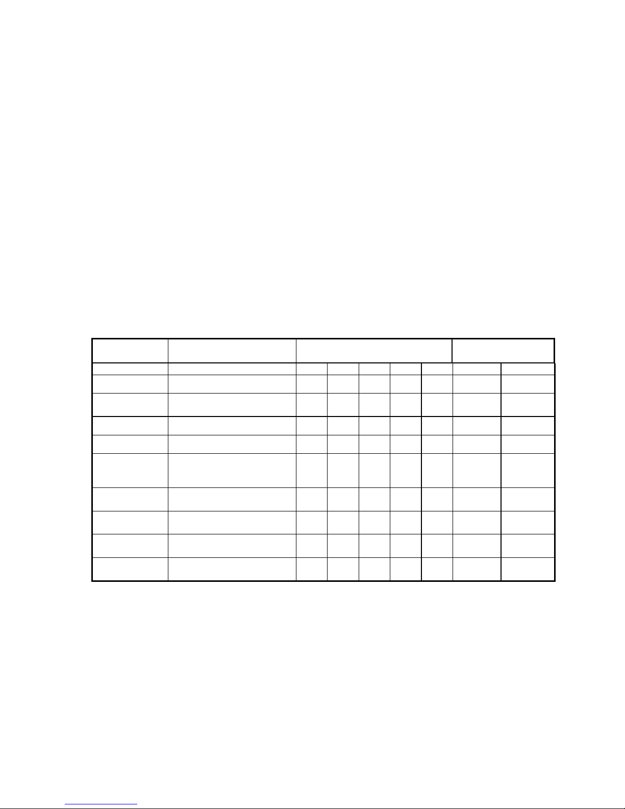
The sensors are available in a variety of enclosures, as detailed below, with five measuring
ranges. A low noise version can be supplied in all packages with a measuring range of
±70μT or ±100μT.
TYPE ENCLOSURE MEASURING RANGE (μT) ORTHOGONALITY
ERROR (°)
70 100 250 500 1000 0.1 0.5
Mag-03MC Cylindrical ***** *
Mag-03MCES Cylindrical - environmentally
sealed connector ***** *
Mag-03MCFL Cylindrical with flying leads ***** *
Mag-03MS Square section ***** *
Mag-03MSES Square section -
environmentally sealed
connector
***** *
Mag-03MSS Square section submersible to
100 metres ***** *
Mag-03IE Cylindrical with independent
elements *****
Mag-03MCTP
(to special order) Cylindrical - two part
construction ***** *
Mag-03MCUP
(to special order) Unpackaged ***** *
TABLE 1. Mag-03 SENSORS
Products are specified as Mag-03 followed by the enclosure code (MC, MCES, MCFL, MS,
MSES, MSS or IE) followed by L for the low noise version only, then the measuring range
(70, 100, 250, 500 or 1000μT).
e.g. Mag-03MSL70 is a square section low noise sensor with a range of ±70μT
Mag-03MC1000 has a cylindrical enclosure and a range of ±1000μT
A re-calibration service is available which is traceable to international standards.

OM1004 ISSUE 20 PAGE 6 OF 30
2 GENERAL DESCRIPTION
This section describes the features common to the Mag-03 range of sensors. Where there are
exceptions they are described under Section 3 detailing the different types of enclosures.
Three fluxgate sensing elements are mounted orthogonally at one end of an enclosure which
also contains the electronic circuitry. The connector is mounted at the opposite end of the
enclosure. The position and direction of each sensing element is shown on the outside of the
sensor, together with the product code, measuring range and serial number.
Details of the enclosures, mounting, connector dimensions, connector pin allocation and the
position of the sensing elements relative to the enclosure are given on the relevant figure
showing the outline and connector detail. The sensor elements are precisely aligned along
the centre lines of the package.
The sensors require a power supply of between ±12V and ±17V and provide three high
precision analog outputs of 0 to ±10V full scale, proportional to the magnetic field along each
axis. For a unit with a full scale range of ±100μT the output voltage for each axis is 0.1V/μT
of the field in the direction of that axis. The relationship between the magnetic field and the
analog output is extremely linear and the frequency response is maximally flat from d.c. to
1kHz with a bandwidth of 3kHz.
The low output impedance of the sensor ensures it can be operated over long cables and
permits it to be interfaced to low impedance data acquisition systems. The zero field offset
error, scale factor, orthogonality and frequency response are individually calibrated.
3 ENCLOSURES
3.1 Mag-03MC - Figure 1
The sensing elements and electronic circuitry are housed in a reinforced epoxy cylindrical
enclosure with a circular connector. The sensor is suitable for use in shallow boreholes but is
not sealed against the ingress of water. A mounting bracket is available as an option. The
label area is recessed and should not be used for clamping.
3.2 Mag-03MCES - Figure 2
This enclosure is the same as the Mag-03MC but features a rugged, seven way sealed
connector to provide a splash-proof unit.
3.3 Mag-03MCFL - Figure 3
This enclosure is identical to the Mag-03MC except that no connector is used, a seven way
connecting cable is moulded within the enclosure with a strain relief grommet. The standard
length of flying lead is 500mm.

OM1004 ISSUE 20 PAGE 7 OF 30
3.4 Mag-03MS - Figure 4
This square section enclosure is manufactured from reinforced epoxy and the sensing
elements are mounted with reference to the base which acts as a datum face.
The Z axis is aligned to this reference face to an accuracy of 0.1°. The orthogonality error
between the magnetic axes is also 0.1°for this sensor compared to the standard 0.5°error for
the other sensors in the range.
The connector is a nine pin D type plug and has pillars for securing the mating connector.
The pillars are tapped with UNC 4-40 threads, standard for this type of connector, but the use
of retaining screws on the mating connector should be avoided unless it can be ascertained
that they contain no magnetic material, which would influence the field at the sensor
elements. Retaining screws commonly contain spring washers or circlips which are
manufactured from ferrous material which render them unsuitable.
3.5 Mag-03MSES - Figure 5
This enclosure is the same as the Mag-03MS but features an environmentally sealed
connector to provide a splash-proof unit. The connector is a rugged, seven way sealed type.
A sealing gasket may be required on the base of the sensor.
3.6 Mag-03MSS - Figure 6
This square section enclosure is designed for marine use and is submersible to depths of 100
metres. The pressure housing is manufactured from polyacetal for minimum water
absorption.
The connector is a seven way marine type and the mating connector is supplied moulded to a
seven way polyurethane jacketed marine cable. The cable is supplied to customer
requirement up to a length of 600 metres.
3.7 Mag-03IE - Figure 7
This sensor has a shortened cylindrical enclosure for the electronics and the three sensing
elements are individually potted and connected to the electronics assembly with flying leads
which have a standard length of 750mm. This allows the user to position the individual
elements independently if required. The sensing elements can be arranged around a sensitive
volume where space is restricted. The connector is the same as for the Mag-03MC.
3.8 Mag-03IE VERSION 2 - Figure 8
This sensor is identical to the Mag-03IE except that Version 2 has a 5m cable attached with a
25 pin ‘D’ type connector. The bandwidth is increased to 5kHz.
3.9 Mag-03MCTP - Figure 9
This enclosure provides a two part construction. The sensing elements and electronics are
contained in two separate cylindrical enclosures connected by a 1000mm ribbon cable and a
simple eight pin dual in-line socket. The sensing elements are completely encapsulated in
epoxy resin within their enclosure. The external connector is the same as for the Mag-03MC.

OM1004 ISSUE 20 PAGE 8 OF 30
3.10 Mag-03MCUP - Figure 10
This arrangement is an “unpackaged” version. The sensing elements are encapsulated in a
cylindrical enclosure but the electronics printed circuit board is simply coated in silicone
rubber and not protected by an enclosure. Two four-way ribbon cables, with a standard
length of 140mm but available in lengths to 500mm, connect the sensing elements to the
electronics board. Connection to the complete unit is by a flying lead.
4 ACCESSORIES
The optional accessories for the Mag-03 range of sensors are as follows:
4.1 Mag-03PSU POWER SUPPLY UNIT
This unit supplies power to any of the Mag-03 sensors from an internal rechargeable battery.
It produces a fully isolated ±12V supply which provides 10 hours of continuous operation.
The battery can be recharged in a few hours using the mains adaptor provided. A high pass
and a low pass filter are provided in each signal path to provide a.c. or d.c. response and to
remove high frequency noise.
Full specifications of the Mag-03PSU are provided in the Mag-03 brochure DS0013 and the
operation manual OM0065.
4.2 Mag-03DAM DATA ACQUISITION MODULE
This is a 24-bit resolution, low speed, six channel data acquisition module which runs under
software control from the user’s PC. Data from one or two triaxial sensors is stored to disk
and may be imported to a suitable spreadsheet for plotting. The module is mains or battery
powered. Full details of the Mag-03DAM are provided in the Mag-03 brochure DS0013 and
in the operation manual OM0658.
4.3 Mag-03SCU SIGNAL CONDITIONING UNIT
This mains powered signal conditioning unit supplies power to a three axis sensor and allows
a filter to be configured with separate controls for the low pass and high pass sections. The
filter is applied to each output channel of the sensor. Control of gain and offset is provided
for each channel independently. Full details are provided in the brochure DS0012 and the
operation manual OM0941.
4.4 Mag-03MC-CU CALIBRATION UNIT
The Mag-03MC-CU is a battery powered unit which produces a sinusoidal alternating
magnetic field of defined frequency and magnitude. It provides a reference magnetic field
for testing the calibration of the Mag-03 sensors which have a cylindrical enclosure. A
temperature stabilised constant current is passed through a single Helmholtz coil with guides
to align each of the sensor axes in turn. Full details are provided in the Mag-03 brochure
DS0013.

OM1004 ISSUE 20 PAGE 9 OF 30
4.5 Mag-03MS-CU CALIBRATION UNIT
The Mag-03MS-CU is a battery powered unit similar to the Mag-03MC-CU above but for
calibration of the Mag-03MS sensors which have a square section. Contact Bartington
Instruments for full details.
4.6 CABLES
Cables are available for connection of the three axis range of sensors to the Mag-03PSU,
Mag-03DAM or Mag-03SCU. Specifications for each of the cables are given in Section 12.
The cables are shown, with their connector pin allocations, in the following figures:
Mag-03MC cable - FIGURE 11 (also used for Mag-03IE)
Mag-03MCES cable - FIGURE 12
Mag-03MS cable - FIGURE 13
Mag-03MSES cable - FIGURE 14
Mag-03MSS cable - FIGURE 15
4.7 Mag-03MC-BR MOUNTING BRACKET (Figure 17)
This mounting bracket for the Mag-03MC cylindrical sensor clamps around the sensor body
and provides mounting holes. The bracket is manufactured from reinforced epoxy resin and
is supplied complete with nylon mounting screws.
4.8 MATING CONNECTORS
All sensors, except for the Mag-03MSS, are supplied with a non-magnetic mating connector
if no cable for connection to a power supply or data acquisition module is purchased.
The Mag-03MSS mating connector must be purchased separately.
5 MOUNTING
The method of mounting will depend on the application and the enclosure. For details of the
mounting arrangements refer to the relevant outline drawing. The use of magnetic materials
in the mounting arrangement must be avoided. All mounting components should be checked
before installation by introducing the component within the immediate vicinity of the sensing
elements of a working magnetometer and observing any variation in the background field.
The analog output is positive for conventional flux direction South to North in the direction
of the arrow shown on the label for each axis. i.e. the maximum positive output will be
obtained from any axis when the arrow points towards magnetic north along the total field
vector.
5.1 Mag-03MC, Mag-03MCES, Mag-03MCFL and Mag-03IE
These sensors may be supported in the Mag-03MC-BR mounting bracket described in
section 4.6. The label area of the sensor is recessed and should not be used for clamping.
5.2 Mag-03MS and Mag-03MSES
These sensors have threaded holes tapped in the base which is also the datum face. The
sensors can be mounted on any flat, non-magnetic surface using the two brass screws

OM1004 ISSUE 20 PAGE 10 OF 30
supplied. A thin gasket or a suitable sealant should be used to seal the base of the units
against water penetration. The absolute maximum screw penetration depth within the
body is 16 mm and this must not be exceeded.
5.3 Mag-03MSS
The Mag-03MSS has a square section pressure housing with three mounting holes, 4 mm in
diameter, drilled through the body and counterbored for cheese-headed screws. Screws are
not provided due to the variable nature of the environmental service conditions which may be
encountered.
5.4 OTHER TYPES
The mounting arrangements for other types will depend on the application.
6 OPERATION
6.1 CONNECTOR PIN ALLOCATION (Figures 1 to 10)
The connector pin or cable colour allocation for the connection to each package type is
shown on the appropriate outline drawing.
6.2 INTERFACE
A simplified interface schematic for the Mag-03 series is shown in Figure 18. The sensor
contains capacitors between the supplies and the signal/power ground line and all lines have
internal fuses to limit the damage if the supplies are reversed or a voltage is applied above the
rated level. These fuses are not replaceable by the user and no access is given to them. NO
PROTECTION IS PROVIDED AGAINST REVERSED POLARITY SUPPLIES OR
SHORT CIRCUITS BETWEEN THE ANALOG OUTPUTS AND THE SUPPLIES OTHER
THAN THESE FUSES.
The analog outputs for the X, Y and Z axes are buffered to give a low output impedance,
enabling the unit to be operated over long cables and interfaced to low impedance data
acquisition systems.
6.3 POWER SUPPLIES
The Mag-03PSU, Mag-03SCU and Mag-03DAM are the ideal power supply units.
Alternatively users may wish to provide their own supply. This would normally provide
±12V and, for the lowest noise applications, ripple in the output should be in the mV region.
The nominal current requirements are +35mA and -6mA for the standard versions and
+26mA and -6mA for the low noise versions with an additional current in proportion to the
measured field. The additional current is 1.4mA per 100μT per axis and will be drawn from
the positive or negative supply depending on the direction of the field.
The current drain is independent of the power supply voltage and the unit will operate with
input voltages down to ±8V. As the output voltage swing is limited to approximately 0.8V
less than the supply levels, for a supply of ±8V the output will operate normally with any
output between +7V and -7V representing a field of 0.7 of the full scale value in each
direction. The scaling factor and linearity will remain at the normal value up to this

OM1004 ISSUE 20 PAGE 11 OF 30
saturation point. The output will remain at the saturation level if the field is increased
beyond this point. Asymmetric supplies may be used provided that the minimum and
maximum voltages are not exceeded for either polarity.
6.4 SIGNAL/POWER GROUND
The two signal/power ground conductors are connected to a common point within the
sensor and the power supply common (power 0 V) should be connected to only one of
them. The other signal/power ground conductor should be used as the signal output
common (signal 0 V). Each signal is then measured between the signal output
conductor and the signal output common. In this way the signal output common carries
no power supply currents.
The minimum current in the power ground conductor is approximately 19mA and, on long
cables, this will give rise to an appreciable potential difference between the power supply end
and the sensor end of the power ground conductor. The use of separate power and signal
ground conductors will ensure that this voltage is not included in the voltage measured
between the signal output and the signal common.
In order to ensure that the power supply return current does not affect the analog
measurements in any way, the following precautions should be observed:
a. A signal common line, separate from the power return line, must be connected between
the Mag-03 magnetic field sensor and any measurement or data acquisition system.
b. If the signal ground line is to constitute a system ground point then a fully floating power
supply must be employed, e.g. a pair of batteries or a fully isolated power supply. A number
of commercially available dc to dc converters fulfil the voltage isolation requirement
adequately. For this arrangement only single ended analog inputs to the data acquisition
system are required for the three axes.
c. If the power supply is to constitute a system ground point then the data acquisition analog
inputs must be of the differential type. Each differential input can then be connected between
the remote end of the signal common line and the individual analog outputs.
d. The above considerations also apply if more than one Mag-03 sensor is used.
e. Any data acquisition system analog inputs should ideally have a very high input
impedance but satisfactory performance can be obtained with impedance’s down to 10kΩ.
Impedance’s below this should be avoided, particularly where very long cables are used.
f. To obtain optimum performance, additional care should be exercised to avoid ground
currents in the signal leads when using the low noise unit.
When using the Mag-03PSU power supply, Mag-03DAM data acquisition module or
Mag-03SCU signal conditioning unit described in Section 4 the above requirements will be
met without further consideration by the user.

OM1004 ISSUE 20 PAGE 12 OF 30
6.5 CABLING
It is recommended that the connecting cable to the sensor is a six core screened cable. Two
cores will be used for positive and negative power supply lines, three cores for output signals
and one core for signal common. The power supply ground should be connected via the
screen which can be expected to have a low resistance. The capacitance between cores
should be less than 200pF per metre. A cable with individually shielded cores should be
considered for long cable applications.
The length of the cable is limited by the voltage drop in the power supply lines and the
capacitance between the cores. For this reason it is recommended that the cable is limited to
a maximum length of 600 metres.
Bartington Instruments can supply cables for connection of the sensor to the Mag-03PSU,
Mag-03DAM or Mag-03SCU. For details see Section 4.5. If no cable is ordered with the
sensor a mating connector is provided.
6.6 CONNECTING POWER
CHECK THAT THE POLARITY OF THE SUPPLY IS CORRECT. Reversed connections
will cause the internal fuses to blow. (see Section 6.2). The power supply should be
connected to the sensor before the supply is energised as this prevents high inrush currents
which could cause damage. Apply the positive and negative supplies simultaneously and
avoid leaving the sensor connected to one polarity only.
6.7 RESPONSE
The analog output V, for any channel, is proportional to the axial component b of the total
field F. If θis the angle subtended between the direction of F and sensing axis of the
fluxgate element, then:
b = F cosθand V ∝F cosθ
6.8 ELECTROMAGNETIC COMPATIBILITY
The Mag-03 range of sensors are not shielded for immunity from, or emission of,
electromagnetic fields. Any shield placed around the sensor will limit the bandwidth of the
sensor response. The emissions generated are at a low level with a primary frequency of
15kHz, being the frequency of the energising field of the sensor. The sensor is required to
respond to magnetic fields within the specified frequency band.
The user should ensure that the sensor is not operated in areas where a high electromagnetic
field exists, even if the frequency is above the bandwidth of the sensor, as false information
may appear due to aliasing. This effect is seen in data acquisition systems when the
frequency of sampling is lower than the frequency of the signal which is being sampled. It
may produce apparent signals at lower frequencies than the noise, which may be within the
frequency band of the sensor. Similarly, the user should not place the sensor near to any
equipment which may be affected by the fields produced by the sensor excitation.
7 PERFORMANCE

OM1004 ISSUE 20 PAGE 13 OF 30
7.1 FREQUENCY RESPONSE
The typical amplitude and phase response for the Mag-03 range of sensors is shown in
Figure 19.
The sensors provide a bandwidth of 3kHz with a maximally flat response to 1kHz.
7.2 NOISE
A typical noise plot for the standard version is shown in Figure 20 and for the low noise
version in Figure 21.
The output signal for each axis will also contain signals at the power line frequency, other
interference and the drive frequency of 15kHz. For many measurements these components
will be outside the response of the readout or recording system. For applications where low
field levels or measurements of the highest resolution are required it will be necessary to
provide a filter to select only the frequency bands of interest.
7.3 OVER RANGE
Sensors are available with ranges from ±70μT, which corresponds to the maximum value of
the earth’s magnetic field, to ±1000 μT. As the field in any axis approaches the full scale
value, the output will rise in proportion until it reaches a value of approximately 0.8V less
than the relevant supply line. The output will then saturate and remain at this level regardless
of any further rise in the field. Very high fields in the hundreds of mT should be avoided as
they may give rise to a few nT shift in offset measured at zero field.
8 SIGNAL PROCESSING
For different applications it may be necessary to process the signal from the sensor in
different ways:
a. In order to increase the sensitivity of the recording system it may be necessary to back-off
the earth’s field and amplify only the changes in the field from the current value. This
requires a high-pass filter, which could be a simple capacitively coupled arrangement or a
multi-pole filter to provide a steep roll off characteristic. These features are all present in the
Mag-03SCU signal conditioning unit.
b. To monitor small signals within the bandwidth of the sensor it may be necessary to
remove the higher frequency noise which is outside the band of frequencies of interest. It
may also be necessary when using sampling data acquisition systems to provide an anti-alias
filter to prevent the appearance of apparent lower frequency components in the recorded
signals due to the strobing effect of the sampling of the high frequency components. The
filter should be a low-pass type with the top of the pass band as far below the sampling
frequency as practical for the application.
c. In applications such as surveillance and magnetic signature monitoring it may be required
to remove both the d.c. standing field and all a.c. noise and pick-up above a set frequency.
The band of interest will be say, 0.01 to 10Hz and a band pass filter can be used to provide
the required signal.

OM1004 ISSUE 20 PAGE 14 OF 30
The output from all fluxgate sensors will contain noise from the driving electronics. For the
Mag-03 range this noise is at 15kHz which is well above the bandwidth of the sensors.
Where low noise operation is required a filter should always be provided to reject the noise
which lies outside the band of interest.
The Mag-03PSU power supply unit, which can be used with all sensors, contains three low
pass filters with a -3dB point at 4.5kHz together with three high pass filters with a
-3dB point at 0.1Hz.
The Mag-03DAM data acquisition module contains anti-aliasing filters which are software
controlled. The high resolution of this unit allows small changes to be recorded even in the
presence of the earth’s field.
The Mag-03SCU signal conditioning unit provides filters with independent control of the low
and high pass filter sections together with offset and gain control for the output of each axis.
9 CARE AND MAINTENANCE
The Mag-03 sensor contains no user-serviceable parts but, provided it is operated within the
design limits, it will require no attention for many years. Surface or dirt contamination
should be removed using a mild detergent solution only. If the connector pins become
contaminated they should be lightly cleaned with a swab of isopropyl alcohol.
The unit must be returned to Bartington Instruments for repair or re-calibration. For the
diagnosis of faults within the unit special equipment is required including a zero gauss
shielded chamber, a calibrated test coil with traceable calibration, and a.c. and d.c. calibrated
constant current sources. Much of this equipment is beyond the scope of normal service
facilities. Any field tests are therefore limited to those which can detect if the magnetic field
sensor and associated circuitry does not produce an analog voltage which is proportional to
the magnetic flux.
If each sensor element in turn is rotated planar to the terrestrial magnetic field, a sinusoidal
analog output should be produced at the relevant output. If this is not the case, or a gross
asymmetry is seen in the output, then a fault clearly exists.
The frequency response of individual channels can be tested by comparing the analog outputs
from each channel using an oscilloscope. If each axis is aligned in turn close to equipment
containing a mains transformer, the stray fields will contain 2nd and 3rd harmonics of the
mains frequency and each channel should give identical results. This will give a rough check
on the operation of each channel to a few hundred Hz.
10 MAGNETIC UNITS AND MEASUREMENTS
10.1 CONVENTIONS
The Mag-03MC analog output is positive for conventional flux direction South to North in
the direction of the arrow given for each axis. The measurement axes are designated X, Y
and Z in the Cartesian co-ordinate system when viewed from the top or non-connector end of
the sensor.

OM1004 ISSUE 20 PAGE 15 OF 30
10.2 MEASUREMENT UNITS
Since 1960 the SI (Systeme Internationale) which is derived from the MKS metric
measurement system has been universally adopted. However, measurements are still
frequently expressed in the older CGS units. For clarity the following relationships may be
useful.
The fundamental equation describing the relationship between magnetic field strength H,
magnetic flux density B and the permeability of free space μo is:
B = μoH
SI is the preferred system of measurement in this manual and these units, together with their
CGS numerical (but not dimensional) equivalents, are shown in the left hand column below.
SI = CGS
B Wbm-2 (Weber per metre2) 104G (Gauss)
or T (Tesla)
H Am-1 (Amperes per metre) 4πx 10-3 (Oe)
It will be seen that the term 4πoccurs in the CGS units. The SI units, however, are
rationalised indirectly by incorporating this term in μo. Thus in the SI system:
μo = 4πx 10-7 Hm-1 (Henries per metre).
Example: For free space If H = 80 Am-1
Then B = 4πx 10-7 x 80 ≈1 x 10⁻⁴ T
Tesla is the preferred unit for flux density in the SI system. A magnetic field sensor can only
be said to measure flux density.
10.3 CONVERSION TABLE
The most common conversion performed will be from Tesla to Gauss and vice-versa. The
following table may be helpful.
SI CGS CGS SI
1 Tesla 10 kGauss 1 kGauss 100 mTesla
1 mT 10 G 1 G 100 μT
1 μT10 mG 1 mG 100 nT
1 nT 10 μG1μG100 pT
TABLE 3 CONVERSION OF SI AND CGS UNITS

OM1004 ISSUE 20 PAGE 16 OF 30
10.4 VECTOR MEASUREMENTS
Each axis produces an analog output Va in response to flux density B in the relationship:
Va = B cos ∅
where ∅is the angle between the flux direction and the direction of the individual sensing
element.
The scalar value of a magnetic field may be computed from the individual X, Y and Z vector
components using the RSS (Root of sum of the squares) where:
B = (Vx2+ Vy2+ Vz2)½
It should be noted that there will be a small error in the result of the calculation of the total
field due to the small error in the orthogonality between the sensing elements. This will be
particularly noticeable when the total field is computed from the values measured with
several orientations of the sensor. The sensor is extremely sensitive in the measurement of
small variations in the total field provided that the orientation is constant i.e. the detector is
stationary. The sensor is therefore limited in applications requiring total field measurement
while moving, as in a towed ferrous metal detector, by the orthogonality error within the
specified tolerance.

OM1004 ISSUE 20 PAGE 17 OF 30
11 TECHNICAL SPECIFICATIONS
11.1 SENSORS
Mechanical, electrical and environmental specifications
Mag-03MC Mag-03MCES
Enclosure reinforced epoxy reinforced epoxy
Dimensions (mm) 25 diameter x 202 length 25 diameter x 207 length
Mounting Mag-03MC-BR bracket Mag-03MC-BR bracket
Connector Hirose RM15TRD10P Amphenol 62GB-51T10-7P
Mating connector Hirose RM15TPD10S Amphenol 62GB-16J10-7S
Operating temperature -40°C to +85°C-40°C to +85°C
Weight 85g 85g
Environmental none splashproof
The specification of the Mag-03MCFL is identical to that of the Mag-03MC except that
connection is made via flying leads and the length is 211mm (Figure 3).
Mag-03MS Mag-03MSES
Enclosure reinforced epoxy reinforced epoxy
Dimensions (mm) square section -
32 x 32 x 152 length square section -
32 x 32 x 166 length
Mounting 2 x M5 fixing holes 3 x M4 clearance holes
Connector ITT Cannon DEM-9P-NMB Amphenol 62GB-12E10-7P
Mating connector ITT Cannon DEM-9S-NMB Amphenol 62GB-16J10-7S
Operating temperature -40°C to +70°C-40°C to +70°C
Weight 160g 160g
Environmental none splashproof
Mag-03IE* Mag-03MSS
Enclosure reinforced epoxy polyacetal
Dimensions (mm) Electronics -
25 diameter x 115 length
Sensor - 8 diameter x 25
length
Sensor-electronics cable-750
square section -
30x 30x 208 length
Mounting Mag-03MC-BR bracket 3 x M4 clearance holes
Connector Hirose RM15TRD10P Impulse IE XSJ-7-BCR
Mating connector Hirose RM15TPD10S Impulse IE XSJ-7-CCP
Operating temperature -40°C to +85°C-10°C to +50°C
Weight 80g 185g
Environmental none 100 metres depth
* For details of Mag-03IE-Version 2 see Figure 8

OM1004 ISSUE 20 PAGE 18 OF 30
Connector pin out - See Figures for versions with flying leads and full details of all types
Mag-03MC/Mag-03MSS/
Mag-03IE*/Mag-03MCTP Mag-03MS Mag-03MCES/
Mag-03MSES
1 X out 1 +12V supply A X out
2 Y out 2 -12V supply B Y out
3 Z out 3 signal/power ground C Z out
4 signal/power ground 4 signal/power ground D signal/power ground
5 signal/power ground 5 Z out E signal/power ground
6 +12V supply 6 X out F +12V supply
7 -12V supply 7 NC G -12V supply
8,9,10 NC 8 Y out
9NC
* For Mag-03IE Version 2 see Figure 8
Mag-03MCFL and Mag-03MCUP
Colour Function
Brown X out
Red Y out
Orange Z out
Yellow signal/power ground
Green signal/power ground
Blue +12V supply
Mauve -12V supply

OM1004 ISSUE 20 PAGE 19 OF 30
Performance specifications (all sensors)
Scaling independent parameters
Supply voltage ±12V to ±17V
Analog output ±10V (±12V supply) swings to within 1V of supply
voltage
Power supply rejection ratio 5μV/V
Output impedance <1Ω
Linearity error <0.0015%
Output ripple 0 to 1kHz maximally flat, ±5% maximum above 1kHz
Calibration accuracy ±0.5%
Bandwidth 0 to 3kHz (0 to 5kHz for Mag-03IE on request)
Orthogonality error -
between sensing axes
Z axis to reference face <0.5°(<0.1°for Mag-03MS and Mag-03MSES)
<0.1°(Mag-03MS and Mag-03MSES)
Internal noise -
standard version
low noise version 7-12pTrms/√Hz at 1Hz
4-6pTrms/√Hz at 1Hz
Supply current
standard version
low noise version +35mA, -6mA (+1.4mA per 100μT for each axis)
+26mA, -6mA (+1.4mA per 100μT for each axis)
Scaling dependent parameters
Measuring range ±70 ±100 ±250 ±500 ±1000 μT
Scaling 143 100 40 20 10 mV/μT
Offset error ±5 ±5 ±12 ±25 ±50 nT
Scaling temperature
coefficient +15 +20 +50 +100 +200 ppm/oC
Offset temperature
coefficient ±0.1 ±0.1 ±0.2 ±0.33 ±0.6 nT/oC
11.2 CABLES
Mag-03MC, Mag-03MS, Mag-03MCES, Mag-03MSES and Mag-03IE
Conductors- : Six 7/0.2 PVC insulated conductors, overall
braided screen and PVC sheath
Type No.- : 7-2-6c Black to Def Stan 61-12, part 4
(Farnell Electronics Stock No. 268-239)
Conductor resistance- : 0.092Ω/m
Capacitance- : 160pF/m
Alternative- : Belden 9536 -5.46mm diameter
Mag-03MSS submersible cable
Conductors- : 3 twisted pairs individually screened,
with polyurethane sheath
Type No.- : PDM Unelco 3T-SP
Conductor resistance- : 0.036Ω/m
Weight- : 0.11kg/m (in air)
Cable connections
Table of contents
Popular Accessories manuals by other brands

Mircom
Mircom MIX-5351AP Installation and maintenance instructions

Anjou
Anjou TT-AD012 user guide

Launch
Launch LTR-03 quick start guide

Extron electronics
Extron electronics RGB 203 Rxi VTG Setup guide

Detcon
Detcon CXT-DM Operator's installation and instruction manual

Manitowoc
Manitowoc G-0800 installation instructions