Page 7 of 15
Pressure Measurement Amplifier DMV 4000
Explanation of parameters:
A1t.u
A1t.uA1t.u
A1t.u :activate or deactivate the cycle of measuring units in operating mode.=
Pass
Pass Pass
Pass
:
Password input for appropriate level
base
basebase
base.
..
.c
cc
c
Z[ FREQ
FREQ FREQ
FREQ : Adjusting the net frequency of the supply voltage.
Choice between 50 or 60 Hz.
INP
INPINP
INP
Z[ Unit
UnitUnit
Unit
: Selection of measuring units between bar, psi und MPa.
Z[ DP
DPDP
DP
: Adjustment of the decimal indication, e.g. 0 = 123 or 3 = 123.937.
Z[ FILT
FILTFILT
FILT
: Delay time (seconds) between value variation and display variation
Z[ RAN
RANRAN
RAN.Lo
LoLo
Lo
: Measuring value begin of sensor
Z[ RAN
RANRAN
RAN.Hi
HiHi
Hi
: Measuring value end of sensor e.g. 500 at 500bar or 5000 at 5000 psi
A0
A0A0
A0
Z[ AO
AOAO
AO.t
tt
typ
ypyp
yp : Adjustment possibilities of analogue signal between
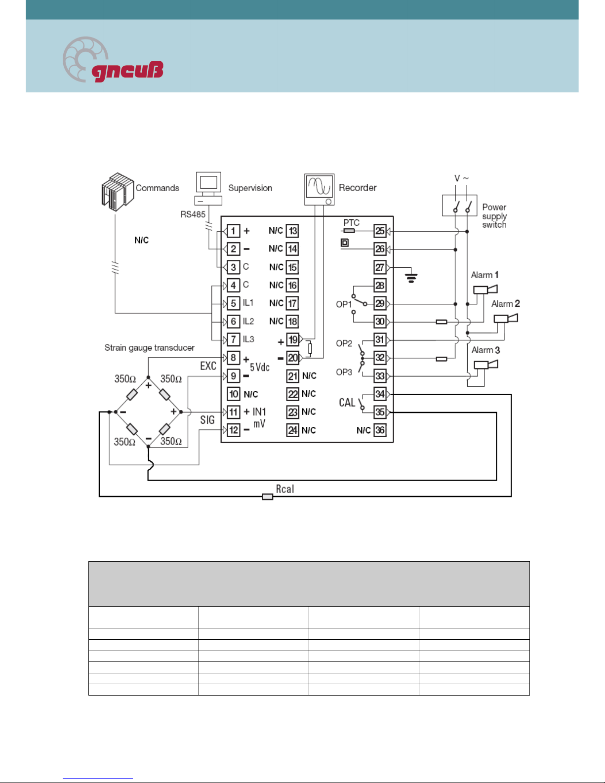
0 – 20 mA (0 – 10 V) or 4 – 20 mA. The 0 - 10V signal is achieved by
connecting a 500 Ωresistor parallel to pins 19 and 20. This resistor
has to be removed for 0-20 mA or 4-20 mA.
Z[ AO
AOAO
AO.Lo
LoLo
Lo
: Adjusting the minimal analogue output signal
Z[ AO
AOAO
AO.Hi
HiHi
Hi
: Adjusting the maximum analogue output signal
sys
sys sys
sys
Z[ Prot
ProtProt
Prot
: Selection of communication protocol between Modbus or Jbus.
Z[=baU
baUbaU
baU
: Adjusting the Baud rate of communication e.g. 9600 = 9600 Baud.
Z[=ParY
ParYParY
ParY : Adjusting the parity
Z[ A r
A rA r
A r : Adjusting the communication address
Z[ Co e
Co eCo e
Co eI
II
I
: Adjusting the password for the configuration level (3333 factory
setting)
Z[ Co e
Co eCo e
Co e2
22
2
: Adjusting the password for the parameter level (1111 factory setting)=
Z[=Co e
Co eCo e
Co e3
33
3
: Adjusting the password fort the calibration level (1234 factory setting)=
ALARM
ALARMALARM
ALARM
= Z[ AL1
AL1AL1
AL1.LT
LTLT
LT
: Choice of self-maintenance/latch feature for Alarm 1- active or
non-active : active = L
LL
Ltch
tchtch
tch
andnon active = none
Z[=AL2
AL2AL2
AL2.LT
LTLT
LT
: Choice of self-maintenance/latch feature for alarm 2 – active or
non-active: active = L
LL
Ltch
tchtch
tch
and non active = none
Z[=AL3
AL3AL3
AL3.LT
LTLT
LT
: Choice of self-maintenance/latch feature for alarm 3 – active or
non-active: active =L
LL
Ltch
tchtch
tch
andnon active = none
Z[=0VT !
0VT !0VT !
0VT !
: Choice of alarm configuration of alarm 1 output signal
Alarm contact is direct/closed (ir
irir
ir)or reverse/open (rev
revrev
rev)
Z[=0VT 2
0VT 20VT 2
0VT 2
: Choice of alarm configuration of alarm 2 output signal.
Alarm contacts is direct/closed Eir
irir
irFor reverse/open (rev
revrev
rev)=
Z[ 0VT 3
0VT 30VT 3
0VT 3
: Choice of alarm configuration of alarm 3 output signal
Alarm contacts is direct/closed (ir
irir
irFor reverse/open (rev
revrev
rev)
C
CC
CAL
AL AL
AL
Z[ CA
CACA
CA.L
LL
LPT
PTPT
PT
: Adjustment of sensor calibration shunt in % of measuring range
Z[=Ehit
EhitEhit
Ehit
: Exit the configuration level, parameter level or the calibration level
AL
ALAL
AL.Sp
SpSp
Sp
Z[=AL
ALAL
AL.1SP
1SP1SP
1SP : Adjusting the alarm set-point for Alarm 1. e.g. 350 bar = 350 with
600 bar sensor=
Z[=AL
ALAL
AL.2
22
2SP
SPSP
SP : Adjusting the alarm set-point for alarm 2 . e.g. 450 bar = 450 with
600 bar sensor
Z[=AL
ALAL
AL.3
33
3SP
SPSP
SP : Adjusting the alarm set-point for Alarm 3. e.g. 500 bar = 500 with
600 bar Sensor
AL
ALAL
AL.
..
.Par
ParPar
Par
Z[=AL
ALAL
AL.
..
.1hY
1hY1hY
1hY : Adjusting the hysteresis of the set-point of alarm 1 in % e.g.
10 (%) of 350 bar = 3,5 bar
Z[=AL
ALAL
AL.2
22
2hY
hYhY
hY : Adjusting the hysteresis of the set-point of alarm 2 in %. e.g.
10 (%) of 450 bar = 4,5 bar
Z[=AL
ALAL
AL.3
33
3hY
hYhY
hY
: Adjusting the hysteresis of the set-point of alarm 3 in %. e.g.