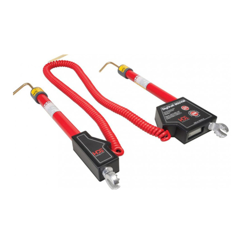
Meilhaus Electronic RedHand Scope User manual

2
LIMITED WARRANTY & LIMITATON OF LIABILITY
Each MEILHAUS ELECTRONIC product is warranted to be free from defects in material
and workmanship under normal use and service. The warranty period of oscilloscope is three years
and the warranty period of accessories is one year, and begins on the date of shipment. Parts,
product repairs and services are warranted for 90 days. This warranty only apply to the original
buyer or customers of a MEILHAUS ELECTRONIC authorized dealer, and does not apply to
fuses, disposable batteries or to any product which, in MEILHAUS ELECTRONIC’s opinion, has
been misused, altered, neglected or damaged by accident or abnormal conditions of operation or
handling. MEILHAUS ELECTRONIC warrants that software will operate substantially in
accordance with its functional specifications for 90 days and that it has been properly recorded on
non-defective media. MEILHAUS ELECTRONIC does not warrant that software will be error
free or operate without interruption.
MEILHAUS ELECTRONIC authorized dealer shall extend this warranty on new and unused
products to end-user customers only but have no authority to extend a greater or different warranty
on behalf of MEILHAUS ELECTRONIC. Warranty support is available if product is purchased
through a MEILHAUS ELECTRONIC authorized sales outlet or Buyer has paid the applicable
international price. MEILHAUS ELECTRONIC reserves the right to invoice Buyer for
importation costs of repair/replacement parts when product purchased in one country is submitted
for repair in another country.
MEILHAUS ELECTRONIC’s warranty obligation is limited, at MEILHAUS
ELECTRONIC’s option, to refund of the purchase price, free of charge repair, or replacement of a
defective product which is returned to a MEILHAUS ELECTRONIC authorized service center
within the warranty period.
To obtain warranty service, contact your nearest MEILHAUS ELECTRONIC authorized
service center or send the product, with a description of the difficulty, postage and insurance.
prepaid (FOB Destination), to the nearest MEILHAUS ELECTRONIC authorized service center.
MEILHAUS ELECTRONIC assumes no risk for damage in transit. Following warranty repair, the
product will be returned to Buyer, transportation prepaid (FOB Destination). If MEILHAUS
ELECTRONIC determines that the failure was caused by misuse, alteration, accident or abnormal
condition of operation or handling, MEILHAUS ELECTRONIC will provide an estimate of repair
costs and obtain authorization before commencing the work. Following repair, the product will be
returned to the Buyer transportation prepaid and the Buyer will be billed for the repair and return
transportation charges (FOB Shipping Point).
This warranty is Buyer’s sole and exclusive remedy and is in lieu of all other warranties,
express or implied, including but not limited to any implied warranty of merchantability or fitness
for a particular purpose. MEILHAUS ELECTRONIC shall not be liable for any special, indirect,
incidental or consequential damages or losses, including loss of data, whether arising from breach
of warranty or based on contract, tort reliance or any other theory.
Since some countries or states do not allow limitation of the term of an implied warranty, or
exclusion or limitation of incidental or consequential damages, the limitations and exclusions of
this warranty may not apply to every buyer. If any provision of this Warranty is held invalid or
unenforceable by a court of competent jurisdiction, such holding will not affect the validity or
enforceability of any other provision.

RedHandScope60MHz HandheldDSO&
DMM
Contents
1
Table of Contents
Chapter Page
1.DECLARATION OF CONFORMITY··················································1
1.1 Declaration of Conformity ······················································································1
1.2 Open the Oscilloscope Parts Box····················· Fehler! Textmarke nicht definiert.
2.SAFETY INFORMATION······································································2
2.1 Safety Terms and Symbols······················································································2
2.1.1 Specific Warning and Caution Terms that Appear throughout the Manual········2
2.1.2 Terms Used on the Product···························································································2
2.1.3 Symbols Used on the Product.·····················································································2
2.2 General Safety Information····················································································3
3. PERFORMING THE GENERAL INSPECTION······························5
3.1 Performing the General Inspection ···································································5
3.3.1 Check whether There is any Damage on it Due to Transportation·······················5
3.3.2 Make a Check on Accessories······················································································5
3.3.3 Make a Check on the Complete Instrument······························································5
4.INPUT CONNECTIONS·········································································6
4.1 Input Connections·········································································································6
4.2 Description for Front Panel and Keys······························································6
5.USING THE SCOPE················································································7

RedHandScope60MHz HandheldDSO&
DMM
Contents
2
5.1 About this Chapter·······································································································7
5.2 Power-Up the Oscilloscope······················································································7
5.3 Oscilloscope Operation Window ·········································································8
5.4 Navigating a Menu ·····································································································10
5.5 Manually Setting the Vertical System, Horizontal System and
Trigger Position ···················································································································10
5.6 Resetting the Oscilloscope······················································································14
5.7 Input Connections·······································································································15
5.8 Displaying an Unknown Signal with Auto Set ··········································15
5.9 Automatic Zero-returning of Trigger Horizontal Position and
Trigger Level Position ······································································································16
5.10 Automatic Measurements ···················································································16
5.11 Freezing the Screen·································································································17
5.12 Using Average for Smoothing Waveforms ···············································18
5.13 Using Persistence to Display Waveforms···················································18
5.14 Using Peak Detection to Display Glitches··················································19
5.15 Selecting AC-coupling ···························································································21

RedHandScope60MHz HandheldDSO&
DMM
Contents
3
5.16 Reversing the Polarity of the Displayed Waveform····························21
5.17 Using Waveform Mathematics Functions·················································22
6.USING THE MULTIMETER·······························································24
6.1 About this Chapter·····································································································24
6.2 Making Meter Connections ··················································································24
6.3 Multimeter Operation Window··········································································24
6.4 Making Multimeter Measurements ·································································25
6.4.1 Measuring Resistance Values·····················································································26
6.4.2 Making a Diode Measurement···················································································26
6.4.3 On-off Test ·····················································································································27
6.4.4 Making a Capacitance Measurement········································································28
6.4.5 Making a DC Voltage Measurement·········································································29
6.4.6 Making a AC Voltage Measurement·········································································30
6.4.7 Making a DC Current Measurement·········································································31
6.4.8 Making an AC Current Measurement·······································································33
6.5 Freezing the Readings ······························································································35
6.6 Taking a Relative Measurement·········································································36
6.7 Selecting Automatic/ManualRange Adjustment······································36
7.ADVANCED FUNCTION OF OSCILLOSCOPE ······················· 38
7.1 About this Chapter·································································································38
7.2 Setting the Vertical CH1 and CH2 ·······························································38

RedHandScope60MHz HandheldDSO&
DMM
Contents
4
7.2.1 Setting the Channel Coupling ················································································39
7.2.2 Make Open and Close Settings on Channel························································40
7.2.3 Adjusting the Probe Scale·······················································································40
7.2.4 Setting of Inverted Waveform················································································40
7.3 Make the Math Function Menu Setting····················································41
7.4 Setting the Trigger System·················································································42
7.5 Triggering Control··································································································43
7.5.1 Edge Triggering ········································································································43
7.5.2 Video Triggering·······································································································44
7.6 Acquiring Mode Setting ······················································································46
7.7 Display Setting ··········································································································46
7.7.1 Display Style··············································································································46
7.7.2 Persistence··················································································································47
7.7.3 XY Mode····················································································································47
7.8 Waveform Saving Setups····················································································48
7.9 Function Setting Menu ························································································49
7.10 Making Automatic Measurements·····························································50
7.11 Setting the Cursor Measurements······························································51

RedHandScope60MHz HandheldDSO&
DMM
Contents
5
7.12 System State Menu·······························································································53
7.13 Setting of Time Base Mode·············································································54
7.14 Data Transmission ·······························································································55
8.TROUBLE SHOOTING········································································57
9.APPENDIX ················· FEHLER! TEXTMARKE NICHT DEFINIERT.
9.1 Appendix a Specifications ······················································································59
9.1.1 Oscilloscope···················································································································59
9.1.2 Meter·······························································································································61
9.1.3 General Specifications·································································································63
9.2 Appendix B: Maintenance and Cleaning······················································64
9.2.1 Common Maintenance·································································································64
9.2.2 Storage of Oscilloscope·······························································································64
9.2.3 Replacing the Lithium Battery Unit··········································································65

RedHandScope60MHz H
andheld DSO & DMM
1-Declaration of Conformity
1
1. Declaration of Conformity
1.1 Declaration of Conformity
REDHAND SCOPE 60MHZ Handheld Digital Storage Oscilloscope & Multimeter
Statement of Conformity
Base on the result using appropriate standards, the product is in conformity with
Electromagnetic Compatibility Directive 89/336/EEC
Low Voltage Directive 73/23/EEC
Sample tests
Standards used:
EN61010.1:2001(2nd edition)
Safety Requirements for Electrical Equipment for Measurement, Control, and
Laboratory use-part 1: General Requirements
EN61326:1997+A1:1998+A2:2001+A3:2003
Electrical Equipment for Measurement, Control and Laboratory use-EMC
Requirements-part 1. General Requirements
EN61000-3-2:2000+A2:2005
Electromagnetic Compatibility (EMC)-part 3: Limits-Section 2: Limits for Harmonic
Current Emissions (Equipment Input Current less than/equal to 16A per phase)
EN61000-3-3:1995+A1:2001
Electromagnetic Compatibility (EMC)-part 3: Limits-Section 3 Limitation of Voltage
Fluctuations and Flicker in Low-Voltage Supply systems for Equipment with Rated
Current less than or equal to 16A
The tests have been performed in typical configuration.
This conformity is indicated by the symbol CE, i.e." Conformité Européenne ".

RedHandScope60MHz H
andheld DSO & DMM
1-Declaration of Conformity
1
1.2 The following Parts are included in the Oscilloscope box.
Refer to figure 1:
# Description Standard Optional
1 Scope meter Test Tool ●
2 Battery Charger ●
3 two Oscilloscope Probes (grey) ●
4 a pair of Test Leads of Multimeter (black and red) ●
5 a Measuring Extension Module for Big Current ●
6 a Measuring Module for Small Capacitance ●
7 a Adjustment Tool of Oscilloscope Probe ●
8 a piece of Serial-port Data Transmission Line or a
Piece of USB Data Transmission Line
●
9 a User’s Manual ●
10 an Operational Optical Disk (include the
transmission software between oscilloscope and
pc)
●
11 a Hard Carrying Case ●

RedHandScope60MHz
Handheld DSO & DMM
3-Performing the General Inspection
2
2. Safety Information
In order to ensure the correct using and the best efficient service, please carefully read this user’s
manual.
2.1 Safety Terms and Symbols
2.1.1 Specific Warning and Caution Terms that Appear throughout the
Manual
Warning: “Warning”identifies conditions and actions that pose hazards to the users.
Caution: “Caution”identifies conditions and actions that may damage the product or
other properties.
2.1.2 Terms Used on the Product
The following terms appears possibly on the product:
Danger: The term “Danger”is used in this manual to indicate that when you read
this mark, personal injury may be caused to you immediately.
Warning: The term “Warning”is used in this manual to indicate that when you read this
mark, personal injury may not be caused to you immediately, but you need to
be cautionary.
Notice: The term “Notice”is used in this manual to indicate that damages may be
caused on this product or other properties.
2.1.3 Symbols Used on the Product.
The following symbols appear possibly on the product.
High voltage
Refer to user
manual
Protective
ground
Measurement
ground Casing ground

RedHandScope60MHz
Handheld DSO & DMM
3-Performing the General Inspection
3
2.2 General Safety Information
Carefully read the following safety information in order to avoid any personal injury and damage
on this product or any products connected with it. This product can only be used in the specified
applications to prevent any possible dangers.
Warning:
To avoid fire or electrical shock. Please use proper power adapter. Use only the power
adapter appointed by the manufacturer and subject to approval of being used in the user’s
country.
Warning:
To avoid fire or electrical shock if a test tool input is connected to more 42V peak (30Vrms)
or on circuits of more than 4800VA:
●Use only insulated voltage probes, test leads and adapter supplied with the test tool, or
indicated by MEILHAUS ELECTRONIC as suitable for the Oscilloscope & Multimeter.
●Before use, inspect voltage probes, test leads and accessories for mechanical damage and
replace when damaged.
●Remove all probes, test leads and accessories that are not in use.
●Always connect the power adapter first to the AC outlet before connecting it to the
Oscilloscope & Multimeter.
●Do not apply voltages that differ more than 400 V from earth ground to any input when
measuring in a CAT Ⅲenvironment.
●Do not apply voltages that differ more than 400 V from earth ground to any input when
measuring in a CAT Ⅱenvironment.
●Do not apply voltages that differ more than 400 V from each other to the isolated input
when measuring in a CAT Ⅲenvironment.
●Do not apply voltages that differ more than 400 V from each other to the isolated inputs

RedHandScope60MHz
Handheld DSO & DMM
3-Performing the General Inspection
4
when measuring in a CAT Ⅱenvironment.
●Do not apply input voltages above the rating of the instrument Use caution when using
1:1 test leads because the probe tip voltage will be directly transmitted to the
Oscilloscope & Multimeter.
●Do not use exposed metal BNC or banana plug connectors.
●Do not insert metal objects into connectors.
●Always use the Oscilloscope & Multimeter only in the manner specified.
●Voltage ratings that are mentioned in the warning are giver as limits for “working
voltage”. The represent V ac rms (50-60Hz) for AC sine wave applications and as V dc
for DC applications. Over voltage Category Ⅲrefers to distribution level and fixed
installation circuits inside a building. Over voltage Category Ⅱrefers to local level ,
which is applicable for appliances and portable equipment .
Only qualified technical personnel are permitted to perform maintenance.
Pay attention to the nominal values of all terminals: To avoid fire or electric shock, please keep
a watchful eye on all nominal values and marks specified for this product. Before any connection
performed on this product, carefully read the user’s manual of the product for further information
of nominal values.
No operation is allowed without the instrument cover plate: If the cover plate or panel has
been removed, do not perform any operation on this product.
No touch is allowed on bare conductors: When the product is powered on, do not touch any bare
joints or parts of the scope meter.
Operation is prohibited in case of any undetermined failure: When in doubt any damage on
this product, consult the qualified personnel for checking on it.
Keep ventilation in good condition: Refer to the user manual for detail installation instructions
in order to fix this product correctly and provide it with good ventilation conditions.
No operation is allowed under a humid environment.
No operation is allowed under an explosive environment.
Keep clean and dry on the product surface.

RedHandScope60MHz
Handheld DSO & DMM
3-Performing the General Inspection
5
3. Performing the General Inspection
3.1 Performing the General Inspection
When you have got a new RedHand Scope series oscilloscope, it is suggested that you should
perform a general inspection on the instrument according to the following steps.
3.3.1 Check whether there is any Damage on it Due to Transportation
If the packing boxes or foam cushions are found in serous damage, keep them in a proper place till
the complete instrument and accessories have passed the electrical and mechanical tests.
3.3.2 Make a Check on Accessories
The accessory list has been described in the picture of Digital Oscilloscope Parts of this manual.
You can make a check and find whether there is any accessory loss with reference to the
Appendix. In case of any accessory loss or damage, consult the MEILHAUS ELECTRONIC
dealer responsible for such a business or the local office of MEILHAUS ELECTRONIC.
3.3.3 Make a Check on the Complete Instrument
If the instrument is damaged in its appearance or it fails in normal operation or performance test,
consult the MEILHAUS ELECTRONIC dealer responsible for such a business or the local office
of MEILHAUS ELECTRONIC. If the instrument is damaged due to transportation, keep the
packing in a proper place and consult the transportation department and the MEILHAUS
ELECTRONIC dealer responsible for such business, who will provide an instrument replacement
or maintenance.

RedHandScope60MHz
Handheld DSO & DMM
4-Input Connections
6
4. Input Connections
4.1 Input Connections
Description:
1. The power adapter is supplied for AC power supply and battery recharging.
2. Multimeter test lead.
3. Multimeter input jacks, including three circular banana jacks and tow square jacks. The three
circular jacks are used for voltage, current and resistance inputs, while the two square jacks
are used for capacitance inputs.
4. Oscilloscope probes.
5. Oscilloscope channel inputs: the upper one is for Channel 1 (CHI1), while the lower one is for
Channel 2 (CH2).
4.2 Description for Front Panel and Keys
Description:
1. Power adapter jack.
2. Serial port. (Option)
3. USB jack.
4. Backlight switch.
5. POWER: Power switch.
6. A: Multimeter current measurement key.
7. V: Multimeter voltage measurement key.
8. R: Multimeter resistance, triode, On/Off and capacitance measurement key.
9. OSC ◄: Oscilloscope left-direction adjustment key.
10. OSC ►: Oscilloscope right-direction adjustment key.
11. OSC OPTION: Oscilloscope setting key.
With the combination application of the four keys OSC ◄, OSC ►, OSC ▲and OSC ▼,
the users can make the following settings circularly by pressing OSC OPTION. The settings

RedHandScope60MHz
Handheld DSO & DMM
4-Input Connections
7
include: Voltage Unit Scale of Channel 1 (CH1 VOL); Voltage Unit Scale of Channel 2 (CH2
VOL); Primary Time base (TIME BASE), zero point position of channel 1(CH1 ZERO), zero
point position of channel 2(CH2 ZERO), trigger horizontal position (TIME) and trigger level
position (TRIG).
When performing Waveform Calculation, the users can also adjust and calculate the Display
Multiplying Factor of waveform (CHM VOL) and the vertical display position (CHM ZERO).
In cursor measurement mode, the users can adjust the positions of Cursor 1 (V1 or T1) and
Cursor 2 (V2 or T2).
12. OSC ▼: Oscilloscope display downward adjustment key.
13. OSC ▲: Oscilloscope display upward adjustment key.
14. OSC/DMM: Operation mode switching key between oscilloscope and multimeter.
15. AUTO SET:
Under the Multimeter Mode, when performing the current or voltage measurement, you can
make a measurement switch between AC and DC with this key pressed; when performing the
resistance measurement, you can select resistance, diode, On/Off or capacitance measurement
circularly with this key.
While this key is used for auto setting under the oscilloscope operation mode.
16. RUN/STOP: key for running or stopping the operation.
17. MENU ▼: Choose the lower item on the menu list.
18. MENU: Show / Hide the menu
19. MENU ▲: Choose the upper item on the menu list.
20. F1~F5: Switch or Adjust options for each menu.
5. Using the Scope
5.1 About this Chapter
This chapter provides a step-by-step introduction to the scope functions. The introduction does not
cover all of the capabilities of the scope functions but gives basic examples to show how to use the
menus and perform basic operations.
5.2 Power-Up the Oscilloscope
Connect oscilloscope to AC power via a power adapter as shown in Figure 1. (The oscilloscope

RedHandScope60MHz
Handheld DSO & DMM
5-Using the Scope
8
may still work with built-in Li-ion battery even without AC power supply)
Turn the oscilloscope on by pressing down the power on/off key POW.
The instrument then performs self checking after power on. Agreeting window and a sentence
“press any key to continue……”will display on the screen when the system finishes self
checking.
The users can press any key to enter the measuring function.
The oscilloscope is powered up in its last setup configuration.
5.3 Oscilloscope Operation Window
Refer to figure 4
figure 4: Oscilloscope Operation Window
Description:
1. Battery electric quantity indicating symbols, including , , and .
2. Auto measurement window 1, in which “f ”means frequency, “T”means cycle, “V”means
the average value, “Vp”the peak-peak value and “Vk”the root-mean-square value.
3. Auto measurement window 2.
4. The pointer indicates the horizontal triggering position.
5. This reading gives the Time Difference between the horizontal triggering position and the
screen centerline. It reads zero when the pointer is in the center of the screen.
6. The trigger state indicates the following information.

RedHandScope60MHz
Handheld DSO & DMM
5-Using the Scope
9
Auto: The oscilloscope is working in the automatic mode and displaying the waveform
under the non-trigger state.
Trig’d: The oscilloscope has detected a trigger and collecting the information generated
after the trigger.
Ready: All pre-triggered data have been captured and the oscilloscope has been ready to
receive trigger signals.
Scan: The oscilloscope can gather and display the waveform data continuously in scanning
mode.
Stop: The oscilloscope has stopped collecting the waveform data.
7. The green pointer shows the trigger voltage level.
8. A hidden-style menu: With the MENU key pressed, you can view or hide the menu.
9. Menu setting options: There are different setting options for different menus.
10. It reads the value of trigger voltage level.
11. The display shows the trigger signal source.
12. The reading gives the value of primary time base.
13. These graphics present the coupling modes of channel 2(CH2). The graphic “~”indicates
AC, the graphic “-”indicates DC.
14. This reading shows the vertical Voltage Unit Scale of CH2.
15. These graphics show the coupling mode of CH1, among which the graphic “~”express
indicates AC, the graphic “-”indicates DC.
16. This reading shows the vertical Voltage Unit Scale of CH1.
17. The blue pointer gives the grounding datum point of the waveform on CH2, which is the zero
position of CH2. No display of this pointer indicates that the channel has not been opened.
18. OSC OPTION operation prompt: There are different prompts for different OSC OPTION
operations.
19. The red pointer gives the grounding datum point of the waveform on CH1, which is the zero
position of CH1. No display of this pointer indicates that the channel has not been opened.
20. Waveform display area. Red waveform represent CH1, blue waveform represent CH2.

RedHandScope60MHz
Handheld DSO & DMM
5-Using the Scope
10
5.4 Navigating a Menu
The following example shows how to use the tool’s menus to select a function, as shown in the
following figure.
1. Press the MENU key to display the Function Menu on the right of the screen and the
corresponding optional settings on the bottom. Press MENU again will hide the Function
Menu.
2. Press the MENU ▲or MENU ▼key to select different function menus.
3. Choose one key from F1 to F5 and press it to change function setting.
Refer to figure 5
figure 5: the Tool’s Menus
5.5 Manually Setting the Vertical System, Horizontal System
and Trigger Position
With the combination application of the four keys OSC LEFT, OSC RIGHT, OSC UP and OSC
DOWN, the users can make the following settings circularly by pressing OSC OPTION. The
settings include: Voltage Unit Scale of Channel 1 (CH1 VOL); Voltage Unit Scale of Channel 2
(CH2 VOL); Primary Time base (TIME BASE), zero point position of channel 1(CH1 ZERO),
zero point position of channel 2(CH2 ZERO), trigger horizontal position (TIME) and trigger
level position (TRIG).
The following example shows how to use OSC OPTION key to make a setting.
1. Press once the OSC OPTION key; the following is displayed at the bottom left side of the
screen, as shown in the figure below.

RedHandScope60MHz
Handheld DSO & DMM
5-Using the Scope
11
◄/►–Time Base
▲/▼–CH1 Vol
Refer to figure 6
figure 6: Voltage Unit Scale of Channel 1
2. Press the key OSC ▲or OSC ▼to adjust the vertical scale of Channel 1 and press OSC
◄or OSC ►to adjust the horizontal time scale.
3. Press OSC OPTION once again, the following display is visible at bottom left side of the
screen, as shown in the following figure.
◄/►–Time Base
▲/▼–CH2 Vol
Refer to figure 7
Table of contents
Other Meilhaus Electronic Measuring Instrument manuals
Popular Measuring Instrument manuals by other brands
Spectra Precision
Spectra Precision DG613 Information guide
Konica Minolta
Konica Minolta REGIUS SIGMA2 Operation manual

connectBlue
connectBlue cB-OZS311 Electrical & Mechanical Datasheet
Labom
Labom BA Series operating instructions

MONARCH INSTRUMENT
MONARCH INSTRUMENT Nova-Pro 100 instruction manual
KERN
KERN DAB-SH-e-1610 Service manual


