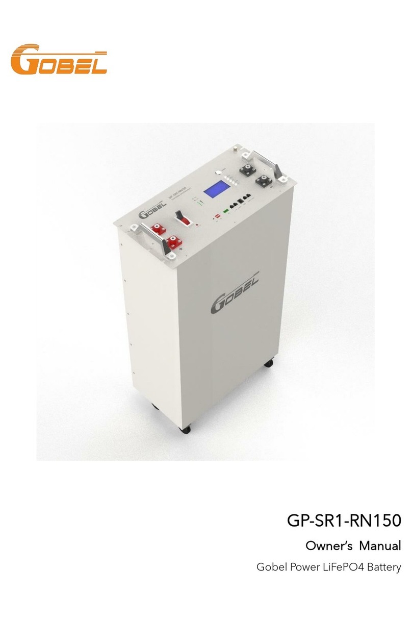
Gobel GP-SR1-PC200 User manual

GP-SR1-PC200
Owner’s Manual
Gobel Power LiFePO4 Battery

1
Table of Contents
1. Information on this Document................................................................ 3
1.1. Validity...................................................................................................3
1.2. Target Group........................................................................................3
1.3. Content and Structure of this Document.........................................3
1.4. Levels of Warning Messages .............................................................3
1.5. Symbols in the Document..................................................................4
1.6. Designation in the Document ...........................................................4
2. Safety........................................................................................................ 5
2.1. Intended Use........................................................................................5
2.2. IMPORTANT SAFETY INSTRUCTIONS.............................................5
3. Scope of Delivery .................................................................................... 8
4. Battery System Overview ......................................................................10
4.1. Battery System Description ............................................................. 10
4.2. Interface ............................................................................................. 10
4.3. Symbols on the System.................................................................... 11
5. Installation..............................................................................................12
5.1. Requirements for Installation.......................................................... 12
5.2. Installation.......................................................................................... 13
6. Electrical Connection ............................................................................ 16
6.1. Overview of the Connection Area.................................................. 16
6.2. Connection Diagram........................................................................ 16
6.3. Data Cable Connection ................................................................... 18
6.4. DC Connection ................................................................................. 20
7. Commissioning......................................................................................22
7.1. Configure the Battery System......................................................... 22
7.2. Switch on the Battery System.......................................................... 22
7.3. Switch on and Commission the Inverter ....................................... 22

2
GP-SR1-PC200 Owner’s Manual
8. Operation...............................................................................................24
8.1. Switch on the Battery System.......................................................... 24
8.2. Switch off the Battery System.......................................................... 24
9. Decommissioning..................................................................................25
10. Extension................................................................................................ 26
11. Troubleshooting....................................................................................27
11.1. LED Light Designation for Errors.................................................... 27
11.2. The battery system is not able to be turned on or off................. 27
12. Maintenance and Storage ....................................................................28
12.1. Cleaning............................................................................................. 28
12.2. Maintenance...................................................................................... 28
13. Disposal of the Battery System .............................................................29
14. Technical Parameters ............................................................................30
15. Contact Information ..............................................................................32
16. Appendix................................................................................................ 33
16.1. Configure BMS of Battery Module................................................. 33
16.2. ADS Table of DIP Switch.................................................................. 37
16.3. Designation of RS232, RS485 and CAN Ports.............................. 38
16.4. LED Indicator..................................................................................... 40

3
1. Information on this Document
1.1.Validity
This document is valid for the LiFePO4 battery module GP-SR1-PC200.
1.2.Target Group
The instructions in this document may only be performed by qualified persons
who must have the following skills:
• Knowledge of how batteries work and are operated
• Knowledge of how an inverter works and is operated
• Knowledge of, and adherence to the locally applicable connection
requirements, standards, and directives
• Knowledge of, and adherence to this document and the associated system
documentation, including all safety instructions
• Training in dealing with the hazards associated with the installation and
operation of electrical equipment and batteries
• Training in the installation and commissioning of electrical equipment
Failure to do so will make any manufacturer's warranty, guarantee or liability
null, and void unless
you can prove that the damage was not due to non-compliance.
1.3.Content and Structure of this Document
This document contains safety information and instructions, scope of delivery,
battery system overview, installation, electrical connection, commissioning,
operation, decommissioning, extension, troubleshooting, maintenance and
storage, disposal of the battery system, technical parameters and contact
information. Please finish reading this document before taking any actions on
the battery system.
1.4.Levels of Warning Messages
DANGER
Indicates a hazardous situation which, if not avoided, will result in death or
serious injury.

4
GP-SR1-PC200 Owner’s Manual
WARNING
Indicates a hazardous situation which, if not avoided, could result in death
or serious injury.
CAUTION
Indicates a hazardous situation which, if not avoided, could result in minor
or moderate injury.
NOTICE
Indicates a situation which, if not avoided, can result in property damage.
1.5.Symbols in the Document
QUALIFIED PERSON
Sections describing activities to be
performed by qualified persons
only.
1.6.Designation in the Document
Battery System
GP-SR1-PC200
BMS
Battery Management System
SOC
State of Charge

5
2. Safety
2.1.Intended Use
The battery system is for residential and works with/without a photovoltaic
system. It is a 51.2V LiFePO4 battery storage system, with the control module on
itself. It could be operated in on-grid and off-grid modes with compatible
inverters.
The battery system could be connected to the PC through USB cable for
maintenance and firmware updating.
The battery system must only be used as stationary equipment.
The battery system is suitable for indoor use only (or well protected place from
raining, snow).
The battery system must only be operated in connection with a compatible
inverter. The list of these inverters could be found at www.gobelpower.com.
The battery system is not suitable for supplying life-sustaining medical devices.
Please ensure that no personal injury would lead due to the power outage of
the battery system.
Alterations to the battery system, e.g., changes or modifications are not allowed
unless the written permission of Gobel Power is achieved. Unauthorized
alterations will void the guarantee and warranty claims. Gobel Power shall not
be held liable for any damage caused by such changes.
The type label should always be attached to the battery system.
2.2.IMPORTANT SAFETY INSTRUCTIONS
The battery system has been designed and tested in accordance with
international safety requirements. However, in order to prevent personal injury
and property damage and ensure long-term operation of the battery system,
please do read this section carefully and observe all safety information at all
times.
2.2.1. Battery Module Leakage
If the battery modules leak electrolytes, contact with the leaking liquid or gas
should be avoided. The electrolyte is corrosive, and the contact may cause skin
irritation and chemical burns. If one is exposed to the leaked substance, do
these actions:
Inhalation: Evacuate the contaminated area, and seek medical help
immediately.

6
GP-SR1-PC200 Owner’s Manual
Eye contact: Rinse eyes with flowing water for 15 minutes and seek medical
help immediately.
Skin contact: Wash the affected area thoroughly with soap and water and seek
medical help immediately.
Ingestion: Induce vomiting and seek medical help immediately.
2.2.2. Firefighting Measures
The battery modules may catch fire when it is put into the fire. In case of a fire,
please make sure that an ABC or carbon dioxide extinguisher is nearby. Water
cannot be used to extinguish the fire.
Full protective clothing and self-contained breathing apparatus are required for
the firefighters to extinguish the fire.
2.2.3. Battery Modules Handling and Storage Guide
The battery modules and its components should be protected from damage
when transporting and handling.
• Do not impact, pull, drag, or step on the battery modules.
• Do not insert unrelated objects into any part of the battery modules.
• Do not throw the battery module into a fire.
• Do not soak the battery modules in water or seawater.
• Do not expose to rain or snow.
• Do not expose to strong oxidizers.
• Do not short circuit the battery modules.
• The battery modules cannot be stored at high temperatures (more than
50°C).
• The battery modules cannot be stored directly under the sun.
• The battery modules cannot be stored in a high humidity environment.
• Do not use the battery modules if it is defective, or appears cracked, broken
or otherwise damaged, or fails to operate.
• Do not attempt to open, disassemble, repair, tamper with, or modify the
battery modules. The battery modules are not user-serviceable.
• Do not use cleaning solvents to clean the battery modules.

7
2.2.4. Warning of Overvoltages
DANGER
Danger to life due to electric shock in case of overvoltages and if surge
protection is missing
Overvoltages (e. g. in the event of a flash of lightning) can be further
conducted into the building and to other connected devices in the same
network via the network cables or other data cables if there is no surge
protection. Touching live parts and cables results in death or lethal injuries
due to electric shock.
• Ensure that all devices in the same network and the inverter are
integrated into the existing surge protection.
• When laying the network cables or other data cables outdoors, it must
be ensured that a suitable surge protection device is provided at the
transition point of the cable from the inverter outdoors to the inside of a
building.
2.2.5. Caution of Weight
CAUTION
Risk of injury due to weight of the battery module
Injuries may result if the battery module is lifted incorrectly or dropped
while being transported or installed.
• Transport and lift the battery module carefully. Take the weight of the
battery module into account.
• Wear suitable personal protective equipment for all work on the battery
system.
2.2.6. Notice of Property Damage
NOTICE
Damage to the battery system due to under voltages
• If the battery system doesn't start at all, please contact Gobel Power
after-sales service within 48 hours.

8
GP-SR1-PC200 Owner’s Manual
3. Scope of Delivery
A1x1
B1x2
B2x2
B3x2
C1x4
C2x2

9
D1x1
D2x1
A1
Battery Module
B1
M6-60 Expanding Screw
B2
Wall Fixture
B3
M6 Screw and Nuts
C1
M8 Screw
C2
DC Power Cable (1m, M8)
D1
Inverter/Parallel Communication Cable
D2
BMS to Computer Communication Cable

10
GP-SR1-PC200 Owner’s Manual
4. Battery System Overview
4.1.Battery System Description
The GP-SR1-PC200 is used as a connected battery for the intermediate storage
of excess PV energy in an inverter system.
It has a built in BMS. The parameters and instruction of BMS could be read on
the Appendix 16.2. The battery system could support the backup function of
inverters and is compatible with both 1 and 3 phase inverters.
WHEN BATTERY SYSTEMS ARE IN PARALLEL CONNECTION, UP TO 15
BATTERY MODULES COULD BE CONNECTED IN PARALLEL.
4.2.Interface
+
DC Positive
-
DC Negative
ADD
Address Dial for parallel connection
RST
Reset BMS
DCT
Dry Contact
CAN
CAN Port for inverter communication
RS485A
RS485 Port for inverter communication
RS485B/RS485C
RS485 Port for parallel connection
RS232
Connection Port for PC communication
250A Breaker
Circuit Breaker, cut off circuit while current >250A
Push to Trip
Push to test the Breaker
On/Off
Power Button, press down to power on

11
4.3.Symbols on the System
Grounding Conductor
This symbol indicates the position for connecting a
grounding conductor.
WEEE Designation
Do not dispose of the system together with the household
waste but in accordance with the disposal regulations for
electronic waste applicable at the installation site.
Keep dry.
Keep the battery modules away from children.
Beware of electrical voltage.
Allowed Installation/Storage Method
Stand on floor.
Other position is
not allowed for
long term storage
Allowed Installation/Storage Method
Each module mounted on the rack.

12
GP-SR1-PC200 Owner’s Manual
5. Installation
5.1.Requirements for Installation
5.1.1. Requirements for Installation Location
a) A solid support surface must be available (e.g., concrete or masonry).
b) The installation location must be inaccessible to children.
c) The installation location must be suitable for the weight and dimensions of
the battery system.
d) The installation location must not be exposed to direct solar irradiation.
e) The installation location must not be close to the fire.
f) The installation location must not be exposed to rain or snow.
g) The altitude of the installation location should be less than 3000m.
h) The ambient temperature should be between -10°C and +50°C.
i) The ambient humidity should be between 5-95%.
5.1.2. Tools
The tools in the following table could be needed during the installation.
Tape Measure
Wrench
Drill
Screwdrive
5.1.3. Safety Gear
It is recommended to wear the following safety gear when dealing with the
battery system.

13
Gloves
Safety Shoes
Safety Goggles
5.2.Installation
QUALIFIED PERSON
CAUTION
Risk of injury due to weight of the battery module
Injuries may result if the battery module is lifted incorrectly or dropped
while being transported or installed.
• Transport and lift the battery module carefully. Take the weight of the
battery module into account.
• Wear suitable personal protective equipment for all work on the battery
system.
Procedure:
1. Take out Battery Module (A1)
and make it stand on the floor.

14
GP-SR1-PC200 Owner’s Manual
2. Drill two M10-60mm holes on
the wall. Distance between two
holes is 470mm. Distance
between hole and floor is
823.3mm.
Then fix Wall Fixture (B2) on
the wall with Expanding
Screws (B1).
3. Push up locks on the wheels to
unlock.
4. Move Battery Module (A1) to
the place between two Wall
Fixtures (B2).
5. Use M6 Screws and Nuts (B3)
to fix Battery Module (A1) on
the Wall Fixtures (B2).

15
6. Push down locks on the wheels
to lock.

16
GP-SR1-PC200 Owner’s Manual
6. Electrical Connection
6.1.Overview of the Connection Area
6.2.Connection Diagram
6.2.1. One Battery Module

17
Turn ADS to [ON,OFF,OFF,OFF].
6.2.2. Multiple Module
If total Charge Current and Discharge Current is below 200A:
Turn ADS of each Battery Module to correspondent address according to
Appendix 16.2.

18
GP-SR1-PC200 Owner’s Manual
If total Charge Current or Discharge Current is above 200A: Use external
busbars which support total Charge Current or Discharge Current.
6.3.Data Cable Connection
QUALIFIED PERSON
6.3.1. Inverter Data Cable Connection
Additionally required mounting material:
One data cable (D1)
Data cable requirements:
The cable length and quality affect the quality of the signal. Observe the
following cable requirements.
• Cable category: Cat5, Cat5e or higher
• Plug type: Metal Shielded RJ45 of Cat5, Cat5e or higher

19
• Shielding: Yes
• UV-resistant for outdoor use
• Straight- through wired cables
Maximum cable length: 10 m.
Procedure:
1. Read the designation of the INVERTER port on Appendix 16.3 and the
inverter manual, and decide whether to modify the data cable.
The designation of INVERTER port on Battery Module could be read in
Appendix 16.3.
Note: Please read the inverter manufacture’s manual, take it into account.
If the data cable has to be modified, please cut the cable, arrange the ware
positions, and crimp the RJ45 connector with a network wire clamp.
2. Plug data cable to CAN or RS485A port. Proper protocol should be chosen
in PC software.
3. If only one Battery Module, Turn ADS of the module to [ON, OFF, OFF, OFF].
If several Battery Modules parallelly connected, turn ADS of the master
module to [ON, OFF, OFF, OFF] and connect inverter with master module.
6.3.2. Parallel Data Cable Connection
Additionally required mounting material (not included in the scope of delivery):
One data cable (D1)
Data cable requirements:
The cable length and quality affect the quality of the signal. Observe the
following cable requirements.
• Cable category: Cat5, Cat5e or higher
• Plug type: Metal Shielded RJ45 of Cat5, Cat5e or higher
• Shielding: Yes
• UV-resistant for outdoor use
• Straight- through wired cables
• Maximum cable length: 10 m.
Procedure:
Table of contents
Other Gobel Batteries Pack manuals
Popular Batteries Pack manuals by other brands

True blue power
True blue power TB40 Series Installation manual and operating instructions

RIVAPOWER
RIVAPOWER VA2004 user manual

Ravpower
Ravpower RP-PB31 user manual

Impact Instrumentation
Impact Instrumentation 306 Series instruction manual

Calumet
Calumet Genesis B Power Port user guide

Panasonic
Panasonic CF-VZSU49U operating instructions