Weco 4K8T User manual

1
Lithium Battery
Model:
4K8T
48V 100Ah
User Manual

2
Copyright WeCo SRL
Without consent of the Company, no unit or individual may excerpt or duplicate the document in part of
in whole, or disseminate any content in any way.
Trade mark Gazette
and other trademarks of WeCo SRL, and all other trademarks or registered trademarks
as referred to herein belong to their respective owners.
Declaration
1.
The Manual covers the detailed specification of lithium iron phosphate battery pack; please read the
instructions carefully before operation and comply with relevant industrial safety regulations. We accept
no responsibility for damages arising from improper operation or any operation in violation of provisions
as stipulated herein.
2.
The document is subject to change by virtue of product version update or other reasons without prior
notice. Unless otherwise agreed herein, the document is only used as the guideline, and no presentations
or suggestions may constitute any express warranty.
Contact Information:
Address: Viale Kennedy 113-121 Scarperia e San Piero Firenze,Italy
Tel: +39 055 0357960

3
Using a special tool:
Static-free:
Disconnect the power supply in operation:
Safety Instruction
Please read the safety instructions before operating the equipment. The safety precautionary
measures as mentioned herein are only used as the supplement to all safety precautions, without
representing all safety precautions to be complied with. Please comply with local safety rules and
regulations when installing, operating and maintaining the equipment. Only trained professionals are
allowed to install, operate and maintain the equipment, and WeCo assumes no responsibility for losses
arising from violating the general safety operation requirement or violating the safety standard for
equipment design, production and use. Installation and maintenance personnel must have the technical
ability of operation in high voltage and AC power supply. Do not wear any conductive object such as
watch, chain bracelet, bracelet and ring when installing, operating and maintaining the equipment, and
keep the equipment away from moisture.
Static electricity would damage veneer on the electrostatic sensitive components; before touching the plug-
in, circuit board or chips, make sure to use correct electrostatic prevention measures.
When operating the power supply, you must first cut off power supply, live operation is prohibited.
Power system provides DC regulated power supply. DC short circuit could cause fatal damage to the equipment.
The high voltage power supply offers the equipment power; direct contact or indirect contact through
wet object with high-voltage power supply may cause fatal danger.
Working in high voltage and AC power, make sure to use a special tool instead of individual tools.
Danger!High Voltage

4
目录Content
1.
产品介绍 Product Introduction............................................................................... 6
2.
技术规格 Technical Specification ............................................................................ 8
2.1
电池组规格参数 Specification Parameters of Battery Pack................................ 8
2.2
指示灯说明 Indicator Instruction................................................................... 9
2.2.1
容量指示 Capacity Indicator................................................................ 9
2.2.2
状态指示 Status Indicator ................................................................... 9
2.2.3
LED 闪动说明 LED Flashing Instruction ..............................................10
2.3
安装指导 Installation Guide .........................................................................10
2.3.1
安装 Installation................................................................................10
2.3.2
接地连接 Grounding Connection .........................................................10
2.3.3
电池组并联 Battery Pack in Parallel .....................................................10
2.3.4
启动系统 Start-up System..................................................................10
2.3.5
通讯口连接 Communication Port Connection........................................10
2.4
操作指导 Operation Guide...........................................................................10
2.4.1
开机 Power On..................................................................................10
2.4.2
关机 Power Off .................................................................................11
2.4.3
充电 Charging ..................................................................................11
2.4.4
放电 Discharging ..............................................................................14
2.5
监控通信 Monitoring and Communication......................................................14
2.5.1
通讯接口定义 Communication Interface Definition ................................14
2.5.2
监控页面 Monitoring Page ..................................................................14
2.5.2 监控页面 Monitoring Page ..................................................................14

5
3.
注意事项 Precautions...........................................................................................15
3.1
安装注意事项 Installation Precautions ..........................................................15
3.2
操作注意事项 Operation Precautions ............................................................16
3.3
维护注意事项 Maintenance Precautions ........................................................16
3.4
常见问题分析及解决方法 FAQ and Troubleshooting .......................................17
3.4.1
欠压告警 Undervoltage Alarm.............................................................17
3.4.2
放电过流保护 Overcurrent Discharging Protection ................................17
3.4.3
温度保护 Temperature Protection .......................................................17
3.4.4
电池无电压输出 No Voltage Output from Battery..................................18
4.
包装、运输、存储 Packaging, Transportation and Storage.......................................18
4.1
包装 Packaging ..........................................................................................18
4.2
运输 Transportation....................................................................................18
4.3
存储 Storage..............................................................................................18
4.4
环境条件 Ambient Conditions.......................................................................18
5.
配件 Accessories ................................................................................................19
6.
电池参数 Battery Parameters................................................................................19

6
1. Product Introduction
The integrated lithium iron phosphate battery pack for communication use consists of lithium
module and battery management system. High-performance battery management system (BMS), which
have functions such as overcharging, over-discharging, over-current, over-temperature, under-
temperature short-circuits protection and 20A current limitation, as well as RS232 and RS485
communication ports, could communicate with computers, read parameters of battery pack and monitor
status of battery pack in real time.
The product, characterized by integration, miniaturization, light weight, no need of operator on duty,
easy use and maintenance, energy conservation, environmental protection, etc., has been widely used
as back-up power source in the communication field such as access network equipment, remote
exchange, mobile communication equipment, transmission equipment, satellite earth station and
microwave communication equipment.
The diagram of the product’s front panel is shown as below:
1.
正极端子 Positive terminal 2.负极端子 Negative terminal 3.断路器 Circuit breaker 4.挂耳
Hangers 5.拉手 Handle 6.复位键 Reset 7. RS485 通讯接口 RS485 communication port 8.RS232 通讯
接口 RS232 communication port 9. ADS 地址扩展拨码 Address extension dial 10. 运行指示灯 Run
indicator11. 告警指示灯 Alarm indicator 12. DO 输出 DO output 13. 容量指示灯 Capacity indicator 14.
接地线点 Grounding terminal

7
All functions are introduced as follows:
(1)Instruction on indicator when charging battery
⚫
4 capacity indicators (CAPACITY) will display according to current battery capacity;
⚫
The run indicator (RUN) will flash every other 1S
⚫
When 4 capacity indicators of battery are normally on and RUN light is off, the battery is fully
charged.
(2)Instruction on indicator when discharging battery
⚫
RUN indicator is normally on
⚫
4 capacity indicators (CAPACITY) will display according to the residual capacity of battery when
discharging.
⚫
When discharging to the protection voltage, the battery goes into the protection status andall
indicators of battery are off.
(3)Battery alarm
In case of battery fault, ALM light shows red and battery fault alarm gives warning.
(4)ADS dial
The dial switch is located on the right of guard plate socket, with the shape as follows:
The dial switch is used to control the address of protection panel. The dial control is a way to
control address by binary system; as shown in the above diagram, 1 shows the least significant bit

8
and 4 shows the most significant bit. When dialing to the upper side, each bit means 1; when
dialing to the lower side, each bit means 0.
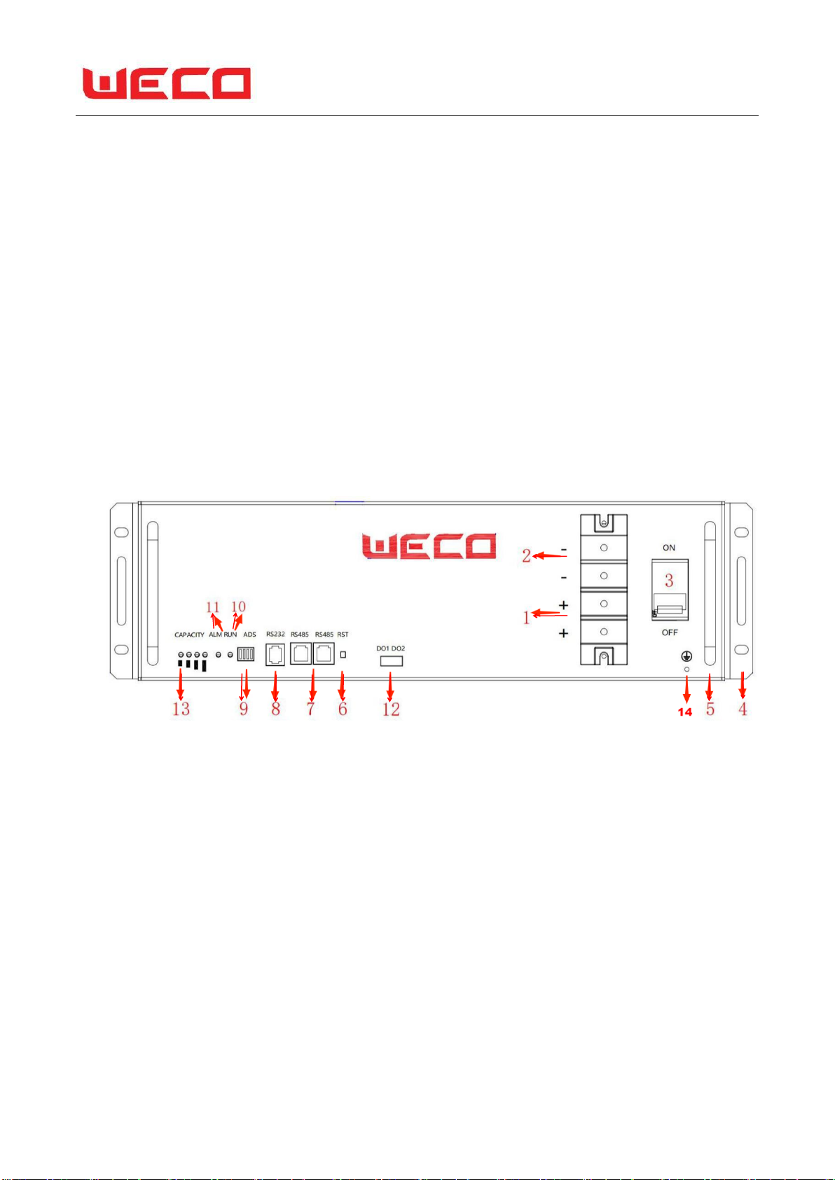
(5)RS232 Monitoring Port
RS232 serial communication is adopted to upload data of battery system; RS232 serial port could realize
centralized background monitoring on the battery system, and transmit the battery system working
status, alarm information, etc. to the remote monitoring center so as to realize remote monitoring.
(6)RS485 Communication Port
RS485 cascade connection communication port. During system cascade connection, RS485
communication way is adopted for the internal Pack system after RS485 serial communication cascade
connection is adopted for data transmission, and the master system acquires Slave Pack data through
Master Pack. Please refer to the specification sheet for the PIN definition of RS485.
(7)Current breaker
Control the battery on & off. When the battery is suffering from short circuit or high current surge, the
current breaker will turn off to effectively protect the battery pack.
(8)RST key
RST: represents resetting; in case of system exceptions, the RST key could be used to reset and recover
the system to the normal operation.
⚫
When BMS is in a dormant state, press RST for 3S then loosen it, the protection panel will be
activated, LED indicators will be lighted up for 0.5S for “RUN” in turn.
⚫
When BMS is in an activated state, press RST for 3S then loosen it, the protection panel will be
dormant, LED indicators will be lighted up for 0.5S from the minimum electricity volume light in turn.
⚫
When BMS is in an activated state, press RST for 6S then loosen it, the protection panel will be
reset, all LED indicators will be simultaneously lighted up for 1.5S.
(9)Sleep and wake up
Sleep
When any one of the following conditions is met, the system enters a low-power mode:
1)
Single or overall over-discharge protection has not been released within 30 seconds.
2)
Release the button after pressing the button for 3 seconds.
3)
The lowest cell voltage is lower than the sleep voltage, and the duration reaches the sleep delay
time (at the same time, no communication, no protection, no balance, and no current are met).
4)
The standby time is more than 24 hours (no communication, no charging and discharging, no
mains).

9
5)
Forcibly shut down through the host computer software.
Before entering sleep, make sure that there is no charger connected, otherwise it will not be able to
enter low power consumption mode.
Wake up
When the system is in low-power mode and meets any of the following conditions, the system will
exit the low-power mode and enter the normal operation mode:
1)
When the charger is connected, the output voltage of the charger must be greater than 48V.
2)
Press the button for 3S, then release the button.
3)
Connect the communication line and turn on the host computer software (because of the over-
discharge protection and enter the dormant state, this method cannot wake up the protection board).
Remarks: After single or overall over-discharge protection, it enters low-power consumption mode,
wakes up every 4 hours and turns on the charge and discharge MOS. If it can be charged, it will exit the
rest
Sleep state enters normal charging; if it fails to be charged after 10 consecutive automatic wakeups,
it will no longer wake up automatically.
When the system is defined as the end of charging, the recovery voltage is not reached after 2 days/48h
of standby (standby time setting value), and it is forced to resume charging until the end of recharging.

10
2.
Technical Parameters
2.1 Specification Parameters of Battery Pack
Nominal Voltage
48V
Nominal capacity
100Ah
Structural dimension of battery pack
W×D×H(mm)
440*480*134mm 3U
Weight
Around 42kg
Delivery voltage
49.2V-50.2V
Discharging cut-off voltage
37.5 V
Charging voltage
54.75V
Monitoring communication
RS232、double RS485 communication port
Charging current limitation
0~20A(the limit current function is closable)
Maximum continuous discharging current
100A
Maximum continuous charging current
100A(When turning off the limit current function)
Internal Resistance
≤80mΩ
Installation Method
19 inch rack mount, wall mount, floor mount, portal frame
mount
Working Environment
Charge:0~55℃, Discharge:-20℃~﹢65℃; humidity:
≤95%;altitude:≤2000m
Protection Function
Overcharging, over-discharging, short-circuit, overload and
over-temperature

11
2.2 Indicator Instruction
2.2.1 Capacity Indicator
Capacity Status
LED Capacity Indicator
●
●
●
●
LED1
LED2
LED3
LED4
0~25%
Light on
Light off
Light off
Light off
25~50%
Light on
Light on
Light off
Light off
50~75%
Light on
Light on
Light on
Light off
75~100%
Light on
Light on
Light on
Light on
The condition of light-on: the monomer voltage is higher than dormant voltage under storage; when
charging and discharging, the capacity indicator light is always on based on the capacity percentage.
2.2.2 State Indicator
Battery
pack State
Protection
/Alarm/No
rmal
RUN
ALM
Electricity Volume
Indication LED
Remarks
●
●
●
●
●
●
Power off
/Dormant
——
Light off
off
off
off
off
off
——
Standby
Normal
Flash 1
Off
According to electricity
volume indication
——
Alarm
Flash3
Charging
Normal
Flash 2
Off
According to electricity
volume indication
Alarm
Flash3
Discharging
Normal
Normally on
Off
According to electricity
volume indication
Alarm
Flash3
Charging
/Dischargin
g/Standby
Protection
According
to
charging/
discharging
state
Flash2
According to electricity
volume indication
The flash state of
electricity volume LED
compare to charging/
discharging state (note:
over-voltage and under
voltage protection alarm
without flash
Charging
/Dischargin
g/Standby
Failure
Light off
Normally
on
Light off
Failure refers to analog-
to-digital Converter of
BMS, charging MOS
damage, disconnection
of temperature
sensor …etc such
hardware breakdown
2.2.3 LED Flashing Instruction
Flashing Ways
On
Off

12
Flash 1
0.25S
3.75S
Flash 2
0.5S
0.5S
Flash 3
0.5S
1.5S
Remark: Make or prohibit LED indicator alarms by host computer, and the factory default is to
make it alarm.
2.3 Installation Precautions
(1)
Unpack prior to installation to check the quantity of the parts and battery appearance;
(2)
Handle the battery gently during handling and placement to prevent it from dropping or
being impacted. The battery shall not be thrown or striken to avoid damaging the battery or
resulting in potential safety hazard;
(3)
Do not put any metal and any article made of the metal conductive material together
with the battery or assemble it into the battery box;
(4)
Install the hanger and handle and measure the battery voltage with a multi-meter. The
general factory voltage of the battery is 49.2V-50.2V;

13
(5)
Check the anode and cathode of the battery prior to wiring; and do not connect
reversely the anode and cathode terminals;
(6)
Wear protective gloves during battery connection. When using such metal tools as
torque wrench, please perform insulating packaging for them and the two ends of the metal
tools such as torque wrench shall not contact the positive and negative terminals of the battery
at the same time to avoid battery short-circuit;
(7)
Before the battery is connected with the peripheral equipment, make the equipment be
in a disconnected state, check whether the connecting polarity of the battery and total voltage
are correct, connect the battery anode with the equipment anode and battery cathode with the
equipment cathode and fix the connecting line,
(8)
Install it according to the selected installation mode:
a)
Installation of standard cabinet (rack): Install the matching hanger for the battery pack
and fix them in the standard cabinet and add tray protection for the battery box.
b)
Installation of wall-mounted box: Prior to installation, please ensure that the wall complies
with the wall-mounted requirements; install the special wall-mounted box of the lithium
battery and fix the battery pack in the wall-mounted box in a hanger manner according to the
location in the design plan;
c)
Installation of integrated indoor and outdoor cabinets (boxes): Install them according to
the installation specification for the customized integrated cabinet (box).
(9)
Installation method diagram:
2.4 Installation Guide
2.4.1 Installation

14
Open the packaging case, take out battery and accessory hangers, and install the hangers to the
battery pack. Fasten the battery pack to 19 inch rack with accessory hanger bolts.
The set accessory hangers and the hanger bolts are not included with the battery and can be
used with the M5*15 screw.
Battery is for indoor installation only (Outdoor installation will require a suitable outdoor rated
cabinet)
19 inch rack or cabinets are not supplied with battery.
Scope of Product Certification does not include external racks or cabinets.
The minimum clearance around batteries is shown as follows:
2.4.2 Cable connection
Connect the battery grounding terminal to the cabinet grounding terminal, so as to guarantee
the connection to be tightened.
The power cable and comms cable between battery and power supply are not provided with the
battery. Power cable’s rating is 8AWG, 200℃,3000V-DC, and red cable is positive while black
one is negative. Ring terminal type is SC16-6.

15
The process of connection is shown as follow:
A air switch isolation is set in the battery as follows:
A overcurrent and disconnection protection device that isolates both positive and negative
conductors simultaneously must be installed between the battery and the inverter.
2.4.3 Battery pack in Parallel
Connect the positive pole of battery pack to the positive pole bus-bar with 16 square red cable,
and connect the negative pole of battery pack to the negative pole bas-bar with 16 square black
cable.
If there are several packs of battery in parallel, ensure that positive poles of each battery pack are
connected and that negative poles of each battery pack are connected.
Each parallel battery must have a overcurrent and disconnection protection device.

16
2.4.4 Start-up System
After completing the battery installation, ensure the battery to be in the close state; and the
battery may be charged or discharged only after the system is started up.
2.4.5 Communication Port Connection
Connect RS232 or RS485 communication port to client’s computer or remote monitoring
equipment with the line of communication.
2.5 Operation Guide
2.5.1 Power on
After installing battery in the close state, connect the positive and negative polar columns of
battery to the switching power supply.
Turn on all overcurrent and disconnection protection devices between battery and inverter or
power supply, and between parallel batteries. Turn on the circuit breaker.
Then charge and discharge the battery, and verify whether the battery’s charging and discharging
performance to be normal or not; conduct the load discharge to the fully-charged battery and
adjust relevant parameters, so as to ensure the battery electricity volume to be effectively
utilized.
2.5.2 Power off
If the battery will be left unused for a long period of time, long press the battery RST key, turn
off the circuit breaker.
Turn off all overcurrent and disconnection protection devices between batteries and inverter or
power supply, and between parallel batteries.

17
2.5.3 Charging
(1)
Correctly set battery parameters according to the following parameter table;
序号
ITEM
VALUE
1
Total charging voltage
Alarm
54(V)
Protection
54.75(V)
Release
51(V)
2
Cell charging voltage
Alarm
3.65V
Protection
3.75V
Release
3.40V
3
Total discharging voltage
Alarm
40.5(V)
Protection
37.5(V)
Release
46.5(V)
4
Cell discharging voltage
Alarm
2.70V
Protection
2.50V
Release
3.10V
5
High temperature during
charging
Alarm
45℃
Protection
50℃
Release
45℃
6
High temperature during
discharging
Alarm
55℃
Protection
65℃
Release
55℃
7
Low temperature during
charging
Alarm
5℃
Protection
0℃
Release
5℃
8
Low temperature during
discharging
Alarm
-15℃
Protection
-20℃
Release
-15℃
9
Environmental high
temperature
Alarm
55℃
Protection
65℃
Release
55℃
10
Environmental low
temperature
Alarm
-15℃
Protection
-20℃
Release
-15℃

18
序号
ITEM
VALUE
11
MOS high temperature
Alarm
95℃
Protection
115℃
Release
85℃
(2)
Maximum charging current is 100A. And 0.2C charging is recommended.
(3)Charging temperature ranges is 0~50℃;humidity<95%。
2.5.4 Discharging
(1)
Inset load to discharge the battery normally
(2)
Battery’s maximum discharging current is 100A
(3)
Battery’s minimum discharging cut-off voltage is 37.5V
2.6 Monitoring and Communication
It is equipped with RS232 interface communicating with upper computer and RS485 interface
performing communication cascade among battery pack.
2.6.1 Communication interface definition
RS232 RS485 DO OUPUT
RS232 6P6C RJ11
RS485 8P8C RJ45
RJ11 PIN
Definition
RJ45 PIN
Definition
1,2,6
NC
1,8
RS485-B
3
TX
2,7
RS485-A
4
RX
3,6
GND
5
GND
4,5
NC
2.6.2 Monitoring Targets
Telemetry: Voltage, current, temperature, SOC, SOH (optional), etc
Tele-command: Charging and discharging state, overcharge/over-current alarm, ambient/battery
pack/PCBA/high battery temperature alarm, low ambient temperature alarm, low battery pack

19
capacity alarm, battery pack temperature/voltage/invalid current sensor alarm, invalid battery alarm
(optional-only alarm without cutting off when monomer voltage difference is too high and exceeds
the limit), invalid battery pack alarm (optional);
Tele-control: Charge/discharge (optional), turning off the alarm voice, smart charging by interval,
current limiting charging method;
Tele-adjusting (optional): charge/discharge administrative parameters of battery pack, etc. which
shall match the output parameters of switch power system.
2.6.3 Monitoring Page
3.
Precautions
3.1 Operation Precautions
(1)
Do not unpack battery box without permission;

20
(2)
Do not let any sharp part of tool touch the battery box surface and scratch or damage
the battery box;
(3)
Do not change the parameter setting in battery management system;
(4)
Do not sprinkle any fluid or powder on the product;
3.2 Maintenance Precautions
Our lithium iron phosphate battery pack, characterized by low self-discharge rate, floating charge
resistance and long using life, is free from maintenance. Its fully smart battery management
system (BMS) replaces human detection process, automatically monitoring the voltage of each
monomer battery of the battery pack and the overall voltage and overall current of battery pack,
performing equilibrium on each monomer battery during charging and discharging process to
avoid overcharging and over-discharging. The automatic detection and protection functions of
battery management system greatly lower the malfunction rate of battery pack and prolong its
service life, and drastically reduce the usage cost of the communication industry. A simple
maintenance and inspection of lithium iron battery can be performed during post installation
and service period. Maintenance intervals can be extended since it is maintenance-free. For
instance, charge it every 3 months.
⚫
Battery shall be maintained by professional technicians; and others are prohibited from
changing battery parameters without permission;
⚫
Check whether polar columns or connecting lines of lithium iron phosphate are loose,
damaged, distorted or eroded, check whether battery shell is damaged or distorted; and
remove the accumulated dust in the air-vent;
⚫
Observe the status of RUN indicator of battery pack, which is in green in normal status.
When only one last capacity indicator remains flashing, it indicates that the capacity is low
and the battery is discharging all the remaining power and shutting the output.
⚫
Pull out the charging cable when the battery is left idle for long time.
⚫
When it malfunctions, the red ALM light of battery pack flashes and send out warnings. In
this case, please check whether the battery is connected in right manner or over-current
exists; then press the reset button to see whether the malfunction is resolved after resetting.
Table of contents
Other Weco Batteries Pack manuals