manuals.online logo
Brands
  1. Home
  2. •
  3. Brands
  4. •
  5. Godin
  6. •
  7. Stove
  8. •
  9. Godin 3465 User manual

Godin 3465 User manual

depuis
1840
chaque
jour
un
peu
plus
...
• • •
Circulaire W
4187
-
99
Documentation à l'adresse de
l'usager et
de
l'installateur
L•ARIÉGEOIS
CONVECTEURS GAZ
,
REF.
3465-
3466-
3467
t-
c A
E
[J
-
~
';=
Q
[
[Er-
1----
1----
éJ
!'--'
~
)
lt
~
r
_L
v
A B c D E F Poids 0
Puissance
de
la
buse
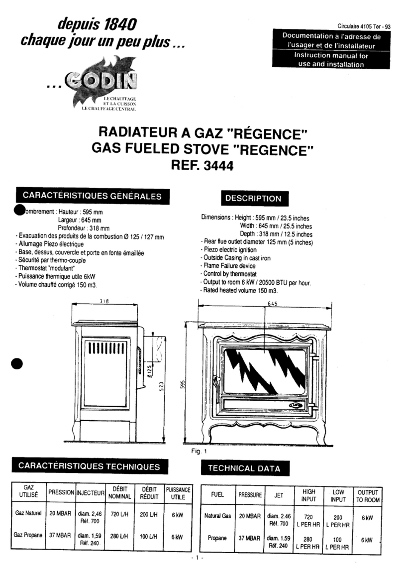
3465
600
mm
710
mm
280
mm
435
mm
190
mm
875
mm
73
kg 111
/97
5,2
kW
3466
740
mm
710
mm
280
mm
435
mm
210
mm
890
mm
78
kg 111
/97
7,2
kW
3467
830
mm
762
mm
350
mm
456
mm
258
mm
989
mm
93
kg
125!111
10,1
kW
CARACTÉRISTIQUES GÉNÉRALES GENERAL CHARACTERISTICS
Evacuation
des
produits
de
la
combustion
arrière
Re
ar
flue
outlet
-Allumage
piezzo
électrique
-Piezzo
electric
ignition
-Base,
dessus,
corps
et
porte
en
fonte
-
Cast
iron
base
-
top
-
tire
box
and
door
-Sécurité
par
thermocouple
-
Control
by
thermostat
-Thermostat
"modulant"
-FI
ame
failure
deviee
-
Bûches
céramiques
-
Vitreous
enamelled
steel
casing
-
Habillage
acier
émaillé
www.pieces-de-poele.com
CARACTÉRISTIQUES TECHNIQUES TECHNICAL
DATA
Débit Débit Débit Débit Débit Puissance
0
injecteur
0
injecteur
G25
Propane réduit réduit nominale
Gaz naturel
G20
Nominal
G
20/G
25
Propane
20mbar
25
mbar
37
mbar
G20
propane
output
2,30
127
6801/h 7601/h 5001/h 2001/h 1501/h
5,2kW
3465
rep.
600
rep.
220
2,54
145
8901/h 9901/h 6501/h 2601/h 1951/h
7,2kW
3466 rep.
750
rep.
280
3467
2,83
1,67
12301/h 13801/h 9001/h 3701/h 2701/h 10,1 kW
rep.
900
rep.
380
INSTALLATION
La mise en placedel'appareil, le raccordement au conduit
defumée, le branchementsurlegaz, ouéventuellement
un
changement de gaz ou même
un
réglage doivent être
réalisés par un spécialiste qualifié.
Les règlesdel'artdoiventêtrescrupuleusementrespectées
notamment:
-Les brasures placées sur le tuyau d'alimentation de gaz
doivent être du type "brasures fortes" (point de fusion
supérieur à 450°).
-L'aération du local doit être suffisante pour alimenter
correctementl'appareil.
-
Le
conduit de fumée doit assurer une bonne évacuation
des produits de la combustion.
-Le
raccordement doit être réalisé de façon rigide.
-Une
vanned'arrêtdoit être placée surla conduite de gaz,
près de l'appareil.
NOTA : Respecter impérativement les prescriptions du
DTU 61.1. (Uniquement pour la France).
-Débit d'air nécessaire à la combustion :
10 m3/heure (3466)
15 m3/heure (3466)
20 m3/heure (3467)
-L'installation doit toujours répondre à la législation en
vigueur du pays où celle-ci est réalisée.
RECOMMANDATIONS
-L'appareildoitobligatoirementêtre raccordé àun conduit
d'évacuation.
-Utiliser du tuyau neuf.
-En employer la plus petite longueur possible.
-Eviter les changements de direction du tuyau et veiller à
ce que le parcours soit aussi vertical que possible.
-Nejamais placer de clé de réglage sur l'évacuation.
-Ne pas raccorder l'appareil à
un
conduit desservant
un
autre appareil.
-Pour
le raccordement du gaz, utiliser un tuyau
012
mm.
IMPORTANT:
Nejamaisfairefonctionnerl'appareil
si
une
vitre est félée ou cassée, la remplacer avant la mise en
service.
-Si
le murarrière est constitué dematériau combustible,
il
est nécessaire de le protégeravec une tôle de60 x 60 cm
minimumsurlaquelleon aurapercéau milieu
un
trou
0100
ou 115 pour le passage de la buse.
INSTALLATION
The
installation
of
the
appliance,
connection
to
the
flue,
connection
to
the
gas
supply,
servicing
or any
adjustment
must
be carried
out
by a
qualified
gas
fn:ter.
The
installation
of
the
appliance
must
be in
accordance
e
with
the
relevant
requirements
of
the
current
Gas
Safety
Installation
and Use Regulations, Building
Regulations.
lt
should
be in
accordance
also
with
any
relevant
requirements
of
the
local
Gas Region and Local
Authority.
-Ali solder
joints
on
the
gas
supply
pipe
must
comply
with
regulations (fusion
temperature
over
450°C).
-Ventilation
of
the
room
must
be
sufficient
to
provide
the
appliance
with
an
adequate
air
supply
10
m3/h
(3465)
15
m3/h
(3466)
20
m3/h
(3467)
-The
flue
system
must
be capable
of
venting
the
product
of
combustion
satisfactorily.
-The appliance
must
be
fastened
to
the
hearth.
-Ali
connections
must
be
effected
using rigid materials.
-A
gas
tap
must
be
put
in
the
pipe near
the
appliance. e
RECOMMENDATIONS
-The
appliance
must
be
connected
to
a
suitable
flue
system.
-
Always
use
the
shortest
length
of
flue
pipe possible.
-
Always
use
new
flue pipe.
-Design
the
flue
system
avoiding
bends and ensuring
the
run
of
flue is
as
near
vertical
as
possible.
-Never install a
damper
in
the
flue
system.
-Do
not
connect
the
appliance
to
a
flue
serving
another
appliance.
-For
connection
to
the
gas
supply
use a 12
mm
0
solder
joint
or
compression
joint.
WARNING
-Never operate a
stave
with
a
damaged
window,
always
have
it
replaced
first.
-
If
the
wall
behing
the
stave
is
combustible,
isolate
it
with
a steel
plate
measuring
at
!east
60
x
60
cm
1
24"
x
24"
with
a
properly
located
and sized
passage
for
the
flue
pipe.
www.pieces-de-poele.com
PREPARATION
AVANT
LA
MISE
EN
SERVICE
-Séparer l'habillage du corps en
soulevant l'ensemble. Le déposer
avec précaution.
-Enlever le panneau inférieur.
-Démonter le hublot en etant les 4
vis qui
le
maintiennent.
-
Poser
le
déflecteur
(
voir
§
suivant).
-Placer les bûches de céramique
selon votre goût mais en laissant
un espace entre-elles.
-Remonter l'ensemble en prenant
garde
que
le
joint
soit
bien
appliqué
Fig 2
ALLUMAGE
Auvrir
le
robinet d'arrêt placé sur la conduite de gaz.
~ourner
la
manette
d'allumage
légèrement
vers la
gauche, l'enfoncer. la maintenir
et
tourner vers
la
gauche
et vers
la
droite
par
intermittence.
Lacher
lorsque la
veilleuse est allumée, puis placer l'index en regard de
la
grande flamme.
PREPARATION BEFORE LIGHTING
-
Remove
casing
from
firebox
gently. as weil
as
lower front panel
-Remove window
by
unscrewing 4
screws.
-
Put
the
baffle
into
place
( see
next
§)
-
Put
ceramic
logs
into
place.
without
forgetting
to leave some
space between
them
-
Put
window
back
1nto
place,
making sure thal the joint
is
airlight.
-Put casing and lower front panel
gently back into place.
LIGHTING
OF
THE
STOVE
-Open the tap on the gas supply.
-First slightly rotate the ignition knob counterclockwise
while depressing
it
; keep it depressed while rotating
it
to
the left and
to
the righi at intervals, to produce sparks.
Release the knob once the pilot !lame burns, and rotate
it
further counterclockwise, until the arrow points
at
the
large !lame
symbol
REMARQUE
· Lors de
l'allumage
et
notamment
si
la 1'::!QlE : On ignition and especially if the flue
is
cold, a
cheminée est froide,
il
peut s'écouler un peu d'eau de
small
quantity
of
condensation
may
drip
from
the
condensation par
le
coupe tirage. Ne pas s'inquiéter, le
downdraught
diverter. This
should
not be a cause for
phénomène s'arrêtera en quelques minutes.
r~concern
and will stop alter a
few
minutes.
IMPORTANT:
En cas d'extinction accidentelle du 1
~~--
WARNING
:
Should
the
burner
go
out
brûleur, attendre 5 minutes avant de reprendre les
êLfS_\
,\ accidentally, let 5 minutes elapse before relighting
manoeuvres d'allumage.
A___
117 B the steve.
VANNE HONEYWELL :
A : Manette d'allumage
et
d'arrêt
APoint
d'arrêt
~Index
D : Manette de thermostat
FONCTIONNEMENT
o---
Le
thermostat permet
le
passage de
la
quantité de gaz
maximale, afin d'élever rapidement
la
température
du
local
Lorsque
la
température correspondant à
la
position sur
laquelle est placée
la
manette du thermostat, est atteinte,
le
thermostat "module", c'est-à-dire fait varier
la
quantité
de gaz admise
au
brûleur, de façon à maintenir
la
température désirée.
Les marques de 1 à 7 figurant sur
la
manette sont des
repères. A l'aide d'un thermomètre placé dans le local,
il
est facile de placer la manette sur
le
repère qui donne
la
température désirée.
Après
un
certain temps d'utilisation de l'appareil,
la
correspondance entre les positions de
la
manette et les
températures obtenues sera acquise.
Si
la
températureextérieureest relativementélevée, seule
la
veilleuse restera allumée.
-c
HONEYWELL
VALVE :
A : Ignition and !lame failure knob
B : "off" position
C:
Index
D : Thermostat control
OPERATION
The thermostat allows the maximum quantity of gas to
flow into the burner
in
orderto
rai
se
the temperature ofthe
room quickly. When the temperature corresponding to
the number selected
on
the thermostat
is
reached, the
thermostat "modulates" the quantity of gas flowing into
the burner
in
order to maintain the temperature desired.
Figures 1 to 7
on
the thermostat knob are to be used
as
a guide. With the aid of a thermometer
in
the room, it
is
simple to adjust the thermostat knob to the setting
required to maintain the desired temperature. With
experience of the equipment, it becomes possible to
judge
what
thermostat
setting
will
produce
the
temperature required.
If the temperature outside
is
relatively high, on certain
settings the pilot light alone may burn.
www.pieces-de-poele.com
REMARQUE :
Si
vous estimez que le brûleur réduit trop
rapidement son allure,
il
est possible de placer l'élément
sensible du thermostat le long du murfixé à 15 cm du sol
environ.
EXTINCTION
VANNE HONEYWELL :
Ramener
la
manette d'allumage en regard du point
d'arrêt.
En
cas d'arrêt prolongé,
il
est recommandé de fermer
la
vanne d'arrêt située sur
la
tuyauterie d'alimentation gaz.
ENTRETIEN
Nous vous rappelons que cette opération doit être
eff7ctuée par
un
spécialiste compétent au moins une fois
par
an.
Le bon fonctionnement aux différentes allures
dans
la
"plage modulée", l'allumage de
la
veilleuse, le
réallumage du brûleur par
la
veilleuse à toutes les allures
doivent être vérifiés en fin d'opération.
L'étanchéité doit être contrôlée.
Pour réaliser l'opération , pratiquer comme suit :
-Oter l'habillage.
-Nettoyer le brûleur et
la
veilleuse.
-Vérifier
l'état du joint, le remplacer
si
nécessaire.
-Démonter eventuellement
le
brûleur. celui-ci est
accessible par le côté droit).
PIÈCES DE REMPLACEMENT
Si
après de longues années le remplacement de certai-
nes pièces s'avère nécessaire ; adressez-vous à votre
FOURNISSEURS ou à tout PROFESSIONNEL DÉTEN-
TEURDE NOTREMARQUE.
Précisez-lui lesindicationsportées sur
la
PLAQUESIGNA-
LÉTIQUE, celle-ciestplacéeà I'ARRIÉRE DE L'APPAREIL
ou
sur
le
BON DE GARANTIE, à conserverimpérativement
même après
la
date de péremption.
En possession des
nomenclatures
et de toute la
documentation technique relative à notre fabrication,
celui-ci sera en mesure de vous fournir rapidement toute
pièce de remplacement et procéder aux réparations
justiciables de ses compétences.
RESPONSABILITÉ
Nous
vou.~
rappelons
que
la responsabilitédu constructeur
se
limite au
produit
tel
qu'il
e.~t
commercialisé et que l'instal-
lation et la mise
en
service
sont
sous la responsabilité entière
de
l'imtallateur
qui devra intervenir selon les règles de l'art
et suivant la prescription de la notice.
Afin
d'améliorer
constamment
la qualité de ses produits, la
Société
GODIN
se
réserve le droit de modifier ses appareils
sans préavis.
NOTE : If a higher output is required, it
is
advisable to
remove the sensitive element of the thermostat (bulb)
from the unit, and fix
iton
the
wall6
inches abovethe floor.
Carry out this operation carefully to avoid breaking the
wire.
TURNING THE BURNER OFF
HONEYWELLVALVE:
Rotate the ignition knob clokwise until the arrow points
at the "off position" point.
If you do not intend to use the appliance for a period of
time we recommend that you turn off the gas supply at
the gas tap
in
the pipe work.
MAINTENANCE
lt is hereby reminded that maintenance must be carried
out at !east once a year by a competent specialist.
good combustion at ali intermediate inputs (modulating
mode), pilot light ignition, re-ignition of the burner by the
pilot light at ali settings must be checked, as weil as
general airtightness. e
Proceed as follows :
-Remove casing.
-Clean bath burner and pilot light.
-Check joint condition and replace if needed.
-Remove burner
if
needed(accessfrom rightside
).
REPLACEMENT PARTS
If after long years of satisfaction you need to replace
some paets, please contact your supplier or one of our
approved dealers.
Give him product data as displayed
in
your warranty
voucher, or
on
the product's nameplate at the back.
Our dealers are
in
possession
of
ali spare part nomencla-
tures and technical data about our products, and
wil~
provide you with the spare parts you need and anYW
maintenance intervention within the scope
of
their
professional competence.
LIABILITY
ft
is reminded
thal
the manufacturer's
liabili~v
ü·
limited to
theproduct as
manufactured
in ils
originalform
(a.~
it leaves
hisfactiry)
and
that
the
product
must
be installedaccording
to manufacturer's recommandations, relevant standards,
regulations
and
codesofpractice,byacompetentprofessional,
acting
under
his
oum
respon.sibility.
ln
the
interest
of
com·tantproductimprovement,
GODIN
S.A.
reserve
the
righi to change specifications without notice.
lmpr1mer1e Graf1prnn
02110
BOHAIN
04.'2004
GODIN-
02120
GUISE-
FRANCE
Tél. · (33) 03 23 05 70 00 Société
Anonyme
au capital
de
1.562.820
€uros
TVA N"
FR
82 835 480 294
RC
Vervins B 835 480 294
Fax usine · (33) 03 23 60
41
05 -Fax SAV : (33) 03 23 05 70 25
internet · http://www.godin.fr
www.pieces-de-poele.com

This manual suits for next models

2

Other Godin Stove manuals

Godin ROUND PETIT GODIN Operator's manual

Godin

Godin ROUND PETIT GODIN Operator's manual

Godin 3444 REGENCE User manual

Godin

Godin 3444 REGENCE User manual

Godin 362105 Guide

Godin

Godin 362105 Guide

Godin OVAL PETIT  3428 User manual

Godin

Godin OVAL PETIT 3428 User manual

Godin PETIT GODIN small round User manual

Godin

Godin PETIT GODIN small round User manual

Godin Le Jurassien 3701 User manual

Godin

Godin Le Jurassien 3701 User manual

Godin REGENCE Instruction manual

Godin

Godin REGENCE Instruction manual

Popular Stove manuals by other brands

Bronpi LORCA-F instruction manual

Bronpi

Bronpi LORCA-F instruction manual

Brunner Iron dog 03 user manual

Brunner

Brunner Iron dog 03 user manual

Pellas X R16 user manual

Pellas X

Pellas X R16 user manual

Morsø 6100 Series Airtight instructions

Morsø

Morsø 6100 Series Airtight instructions

Woodwarm Stoves Fireblaze Installation and operating instructions

Woodwarm Stoves

Woodwarm Stoves Fireblaze Installation and operating instructions

Defy DSS 617 instruction manual

Defy

Defy DSS 617 instruction manual

joule 5 Installation and operating insctructions

joule

joule 5 Installation and operating insctructions

Bartscher FA092M00 Installation, operation & maintenance instructions

Bartscher

Bartscher FA092M00 Installation, operation & maintenance instructions

Parkray Inset Chevin 8 Installation and operating instructions

Parkray

Parkray Inset Chevin 8 Installation and operating instructions

Clarke JUNIOR FRANKLIN user guide

Clarke

Clarke JUNIOR FRANKLIN user guide

THERMOROSSI PELLET AIR 11 Installation, use and maintenance guide

THERMOROSSI

THERMOROSSI PELLET AIR 11 Installation, use and maintenance guide

MCZ KLIN COMFORT AIR 8 M1 installation guide

MCZ

MCZ KLIN COMFORT AIR 8 M1 installation guide

The Auckland CL Installing and operating insructions

The Auckland

The Auckland CL Installing and operating insructions

Heartland Sweetheart 2603 Installation and operating instructions

Heartland

Heartland Sweetheart 2603 Installation and operating instructions

IKI KIVI-IKI Instructions for installation

IKI

IKI KIVI-IKI Instructions for installation

Mendip Stoves 5 standard Operating/service instructions

Mendip Stoves

Mendip Stoves 5 standard Operating/service instructions

Snow Peak GigaPower GS-230 instruction manual

Snow Peak

Snow Peak GigaPower GS-230 instruction manual

Olymberyl MULTI-FUEL STOVE operating manual

Olymberyl

Olymberyl MULTI-FUEL STOVE operating manual

manuals.online logo
manuals.online logoBrands
  • About & Mission
  • Contact us
  • Privacy Policy
  • Terms and Conditions

Copyright 2025 Manuals.Online. All Rights Reserved.