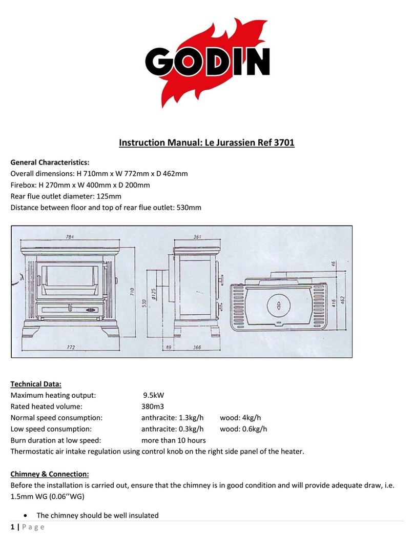
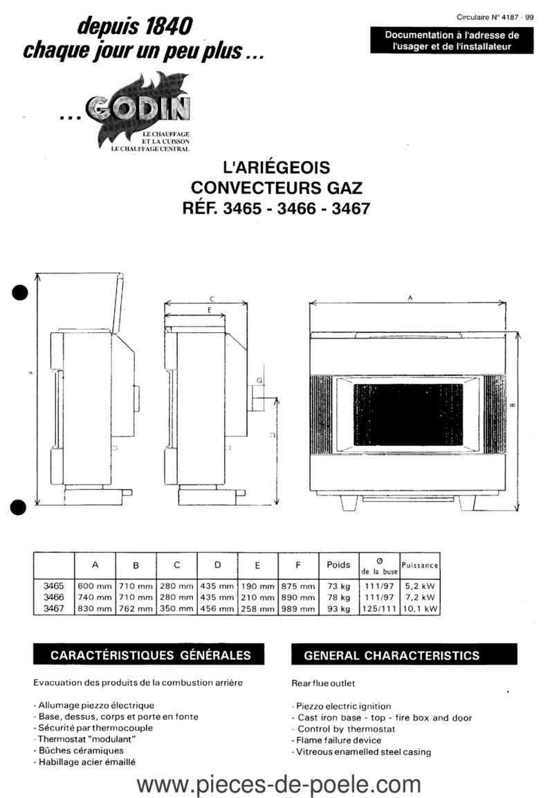
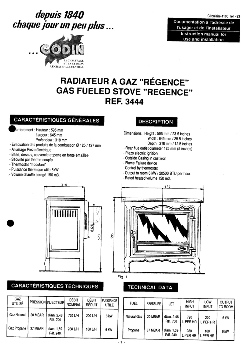
Godin REGENCE Instruction manual

depuis
1840
chaque
jour
un
peu
plus
...
• • •
Circulaire
41
05
Ter
-
93
Documentation
a l'adresse de
l'usager
et de
l'installateur
Instruction
manual
for
use
and
installation
RADIATEUR A
GAZ
"RÉGENCE"
GAS FUELED STOVE "REGENCE"
REF. 3444
CARACTÉRISTIQUES
GÉNÉRALES
eombrement :
Hauteur
:
595
mm
Largeur
:
645
mm
Profondeur
:
318
mm
-Evacuation
des
produits
de
la
combustion
0
125
/127
mm
-
Allumage
Piezo
électrique
-
Base,
dessus,
couvercle
et
porte
en
fonte
émaillée
-
Sécurité
par
thermo-couple
-
Thermostat
"modulant'
-
Puissance
thermique
utile
6kW
-Volume
chauffé
corrigé
150
m3.
318
-
h f
111111111
'--/
,1
' \
r;
'6:1
~
,..,
N
.r>
(
)
-
CARACTÉRISTIQUES TECHNIQUES
GAZ
PRESSION
INJECTEUR
DÉBIT DÉBIT
UTILISÉ
NOMINAL
RÉDUIT
Gaz
Naturel
20
MBAR
diam.
2,46
720UH
200
UH
Réf.
700
Gaz
Propane
37MBAR
diam.
1,59
280UH
100UH
Réf.
240
PUISSANCE
UTILE
6kW
6kW
DESCRIPTION
Dimensions
:
Height
:
595
mm
/23.5
inches
Width
:
645
mm
/25.5
inches
Depth:
318
mm
1
12.5
inches
-
Rear
flue
outlet
diameter
125
mm
(5
inches)
-
Piezo
electric
ignition
-
Outside
Casing
in
cast
iron
-
Flame
Failure
deviee
-
Control
by
thermostat
-
Output
to
room
6
kW
1
20500
BTU
per
hour.
-
Rated
heated
volume
150
m3.
45
Fig. 1
TECHNICAL
DATA
FUEL
PRESSURE
JET
HIGH
INPUT
Natural
Gas
20
MBAR
diam.
2.46
720
Réf.
700
L
PER
HR
Propane
37MBAR
diam.
1.59
280
Réf.
240
L
PER
HA
- 1 -
LOW
OUTPUT
INPUT
TOROOM
200
6kW
L
PER
HR
100
6kW
L
PERHR
www.pieces-de-poele.com

INSTALLATION
La
mise
en
place
de
l'appareil,
le
raccordement
au
conduit
de
fumée,
le
branchement
sur
le
gaz,
ou
éventuellement
un
changement
de
gaz
ou
même
un
réglage
doivent
être
réalisés
par
un
spécialiste
qualifié.
-
Fixer
d'abord
la
buse
sur
l'appareil
à
l'aide
des
vis
fournies.
Les
règles
de
l'art
doivent
être
scrupuleusement
respectées
notamment
:
-
Les
brasures
placées
sur
le
tuyau
d'alimentation
de
gaz
doivent
être
du
type
•
brasures
fortes,
(point
de
fusion
à
450°}.
-
L'aération
du
local
doit
être
suffisante
pour
alimenter
correctement
l'appareil.
-
Le
conduit
de
fumée
doit
assurer
une
bonne
évacuation
des
produits
de
la
combustion.
-
L'appareil
doit
être
fixé
au
sol.
-
Le
raccordement
doit
être
réalisé
de
façon
rigide.
-Une
vanne
d'arrêt
doit
être
placée
sur
la
conduite
de
gaz,
près
de
l'appareil.
NOTA
:
Respecter
impérativement
les
prescriptions
de
DTU
61.1.
RECOMMANDATIONS
-
L'appareil
doit
obligatoirement
être
raccordé
à
un
conduit
d'évacuation.
-
Utiliser
du
tuyau
neuf.
-
En
employer
la
plus
petite
longueur
possible.
-
Éviter
les
changements
de
direction
du
tuyau
et
veiller
à
ce
que
le
parcours
soit
aussi
vertical
que
possible.
-
Ne
jamais
placer
de
clé
de
réglage
sur
l'évacuation.
-
Ne
pas
raccorder
l'appareil
à
un
conduit
desservant
un
autre
appareil.
-Pour
le
raccordement
du
gaz,
utiliser
un
tuyau
0
12
mm.
IMPORTANT
:
Ne
jamais
faire
fonctionner
l'appareil
si
une
vitre
est
fêlée
ou
cassée,
la
remplacer
avant
la
mise
en
service.
ALLUMAGE
-
Vérifier
la
bonne
position
des
déflecteurs.
-
Les
remettre
éventuellement
en
place
comme
indiqué
(Fig.
2)
.
•
-
Mettre
les
bûches
de
céramique
en
place
selon
votre
goût.
-
Soulever
la
grille
d'accès
à
la
manette
gaz
(Fig.
4).
INSTALLATION
Fix
flue
spigot
tc
rear
of
steve.
The
installation
of
the
appliance,
connection
tc
the
flue,
connection
tc
the
gas
supply,
servicing
or
any
adjustment
must
be
carried
out
by
a
qualified
gas
fitter.
The
installation
of
the
appliance
must
be
in
accordance
with
the
relevant
requirements
of
the
current
Gas
Safety
(Installation
and
Use)
Regulations,
Building
Regulations.
lt
should
be
in
accordance
also
with
any
relevant
requirements
of
the
local
Gas
Region
and
Local
Authority.
-
Ali
solder
joints
on
the
gas
supply
pipe
must
comply
with
regulations
(fusion
temperature
over
450°
C).
-
Ventilation
of
the
room
must
be
sufficient
to
provide
the
appliance
with
an
adequate
air.
supply.
-
The
flue
system
must
be
capable
of
venting
the
products
of
combustion.
-
The
appliance
must
be
secured
to
the
hearth.
-
Ali
connections
must
be
effected
using
rigid
materials.
-A
gas
tap
must
be
put
in
the
pipe
near
the
appliance.
RECOMMENDATIONS
-
The
appliance
must
be
connected
to
a
suitable
flue
system.
-
Always
use
the
shortest
lenght
of
flue
pipe
possible.
-
Always
use
new
flue
pipe.
-
Design
the
flue
system
avoiding
bends
and
ensuring
the
run
of
flue
is
as
near
vertical
as
possible.
-
Never
instail
a
damper
in
the
flue
system.
-
Do
not
connect
the
appliance
tc
a
flue
serving
another
appliance.
-
For
connection
tc
the
gas
supply
use
a
12
mm
pipe
with
solder
joint
or
compression
joint.
WARNING
:
Never
operate
the
steve
if
the
front
window
is
damaged.
Always
have
the
window
replaced
before
relighting
the
steve.
LIGHTING OF THE STOVE
-
Check
that
the
baffles
are
in
the
right
position
inside
the
firebox.
-
If
necessary,
put
them
into
position
as
shown
below
(Fig.
2).
Fig.
2
-
Put
lower
outside
baffle
in
place
(see
addendum).
-
Lift
the
lid
on
top
of
the
steve
for
access
tc
the
contrais
(Fig.
4).
- 2 -
www.pieces-de-poele.com

MISE
EN
PLACE
DU
DÉFLECTEUR
INFÉRIEUR
-
Placer
le
déflecteur
sous
l'appareil
et
faire
coïncider
les
pattes
de
fixation
avec
les
4
vis
visibles,
fixer
en
utilisant
les
écrous
fournis
(Fig.
3).
MISE
EN
PLACE
DES
BÛCHES
-
Placer
4
bûches
sur
le
support
selon
votre
goût
mais
en
ménageant
des
espaces
entre-elles.
-
Condamner
ensuite
la
porte
de
l'appareil
à
l'aide
de
la
vis
fournie
(Fig.
5).
. 3 .
FITTING
THE
LOWER
BAFFLE
·
Put
the
baffle
under
the
steve
so
that
its
fixture
heles
face
the
four
visible
screws
and
fasten
with
the
nuts
supplied
(Fig.3).
INSTALLATION
OF
THE
LOG
SET
-
First
put
4
logs
onto
the
support
without
forgetting
to
leave
sufficient
space
between
them.
-
Lock
the
door
with
the
screw
provided
(Fig.5).
'
.
Fig.
4
www.pieces-de-poele.com

VANNE
HONEYWELL:
Tourner
la
manette
d'allumage
légèrement
vers
la
gauche,
l'enfoncer,
la
main-
tenir
et
tourner
vers
la
gauche
et
vers
la
droite
par
intermittence.
Lacher
lorsque
la
veilleuse
est
allumée,
puis
placer
l'index
en
regard
de
la
grande
flamme.
REMARQUE
:
Lors
de
l'allumage
et
notamment
si
la
cheminée
est
froide,
il
peut
s'écouler
un
peu
d'eau
de
condensation
par
le
coupe
tirage.
Ne
pas
s'inquiéter,
le
phénomène
s'arrêtera
en
quelques
minutes.
IMPORTANT
:
En
cas
d'extinction
accidentelle
du
brûleur,
attendre
5
minutes
avant
de
reprendre
les
manoeuvres
d'allumage.
HONEYWELL
VALVE:
First
slightly
rotate
the
ignition
knob
counterclockwise
while
depressing
it
;
keep
it
depressed
while
rotating
it
to
the
left
and
to
the
right
at
intervals,
to
produce
sparks.
Release
the
knob
once
the
pilot
flame
burns,
and
rotate
it
further
counterclockwise,
until
the
arrow
points
at
the
large
flame
symbol.
NOTE
:
On
ignition
and
especially
if
the
flue
is
cold,
a
small
quantity
of
condensation
may
drip
from
the
downdraught
diverter.
This
should
not
be
a
cause
for
concern
and
will
stop
alter
a
few
minutes.
WARNING
:
Should
the
burner
go
out
accidentally,
let
5
minutes
elapse
before
relighting
the
stove.
VANNE
HONEYWELL
:
A:
Manette
d'allumage
et
d'arrêt
B:
Point
d'arrêt
C:
Index
D:
Manette
de
thermostat
HONEYWELL
VALVE
:
A:
Ignition
and
flame
failure
knob
B:
"off"
position
C:
Index
D:
Thermostat
control
Fig.
6
MISE
EN
PLACE
DU
BULBE
DU
THERMOSTAT
-
Déposer
le
côté
droit
de
l'appareil
(Fig.
4)
puis
dérouler
soigneusement
le
capillaire
et
placer
le
bulbe
sous
le
déflecteur
dans
les
clips
prévus
à
cet
effet
(Fig.
3).
(il
est
possible
de
placer
le
bulbe
sur
le
mur
arrière
à
15
cm
du
sol
si
l'on
souhaite
une
réaction
retardée
du
thermostat).
FONCTIONNEMENT
Le
thermostat
permet
le
passage
de
la
quantité
de
gaz
maximale,
afin
d'élever
rapidement
la
température
du
local.
Lorsque
la
température
correspondant
à
la
position
sur
laquelle
est
placée
la
manette
du
thermostat,
est
atteinte,
le
thermostat
«module,,,
c'est-à-dire
fait
varier
la
quantité
de
gaz
admise
au
brûleur,
de
façon
à
maintenir
la
température
désirée.
Les
marques
de
1à 6
figurant
sur
la
manette
sont
des
repères.
A
l'aide
d'un
thermomètre
placé
dans
le
local,
il
est
facile
de
placer
la
manette
sur
le
repère
qui
donne
la
température
désirée.
Après
un
certain
temps
d'utilisation
de
l'appareil,
la
correspondance
entre
les
positions
de
la
manette
et
les
températures
obtenues
sera
acquise.
Si
la
température
extérieure
est
relativement
élevée,
seule
la
veilleuse
restera
allumée.
REMARQUE
:
Si
vous
estimez
que
le
brûleur
réduit
trop
rapidement
son
allure,
il
est
possible
de
placer
l'élément
sensible
du
thermostat
le
long
du
mur
fixé
à
15
cm
du
sol
environ.
-
4-
FITTING THE THERMOSTAT BULB
-
Remove
the
stove's
right
side
(Fig.
4),
unroll
the
wire
very
carefully
and
put
the
bulb
under
the
baffle
into
the
clips
(Fig.3).
(The
bulb
can
also
be
fixed
onto
the
wall
behind
the
stove
approx
15
cm/6
inches
above
floor
level,
in
arder
to
pick
up
the
room
temperature).
OPERATION
The
thermostat
allows
the
maximum
quantity
of
gas
to
flow
into
the the
burner
in
order
to
raise
the
temperature
of
the
room
quickly.
When
the
temperature
corresponding
to
the
number
set
on
the
thermostat
is
reached,
the
thermostat
varies
the
quantity
of
gas
flowing
into
the
burner
in
arder
to
maintain
the
temperature
desired.
The
figures
1
to
6
on
the
thermostat
knob
are
to
be
used
as
a
guide.
With
the
aid
of
a
thermometer
in
the
room,
it
is
simple
to
adjust
the
thermostat
knob
to
the
setting
required
to
maintain
the
desired
temperature.
With
experience
of
the
equipment,
it
becomes
possible
to
judge
what
thermostat
setting
will
produce
the
temperature
required.
If
the
temperature
outside
is
relatively
high,
on
certain
settings
the
pilot
light
alone
may
burn.
NOTE
:
The
thermostat
bulb
should
be
fixed
onto
the
wall
behind
the
stave,
approximately
15
cm
(6
inches)
above
floor
level.
This
is
to
ensure
thal
the
thermostat
picks
up
the
temperature
of
the
room
and
not
the
temperature
of
the
stave
(see
addendum).
www.pieces-de-poele.com

EXTINCTION
VANNE
HONEYWELL
•
Ramener
la
manette
d'allumage
en
regard
du
point
d'arrêt.
CHANGEMENT
DE
GAZ
Nous
vous
rappelons
que
cette
opération
doit
être
effectuée
par
un
spécialiste
compétent.
Le
bon
fonctionnement
aux
différentes
allures
dans
la
"plage
modulée",
l'allumage
de
la
veilleuse,
le
réallumage
du
brûleur
par
la
veilleuse
à
toutes
les
allures
doivent
être
vérifiés
en
fin
d'opération.
L'étanchéité
doit
également
être
contrôlée.
Pour
réaliser
1
opératm
pratiquer
comme
suit
•
-
Ouvrir
la
porte
avant.
-
Soulever
légèrement
le
brûleur
à
son
extrémité
gauche
et
le
dégager
avec
précaution,
sans
forcer.
-
Démonter
1
'Injecteur
ainsi
dégagé.
-
Remettre
en
place
le
nouvel
injecteur
(marqué
700
pour
le
gaz
naturel
et
340
pour
le
propane).
-
Changer
l'injecteur
de
veilleuse
(marqué
46
pour
le
propane
et
e
pour
le
gaz
naturel),
-
Celui-ci
est
accessible
après
avoir
ôté
le
tuyau
d'alimentation
du
bec
de
la
veilleuse_
-
Remettre
le
brûleur
en
place,
et
procéder
aux
vérifications.
-
Régler
éventuellement
la
valeur
du
débit
réduit
(la
vis
de
réglage
est
placée
sous
l'Index
du
thermostat
et
en
bas).
- 5 -
TURNING THE BURNER OFF
HONEYWELL
VALVE
•
Rotate
the
ignition
knob
clockwise
until
the
arrow
points
at
the
"off
po-
sition,,
point.
CONVERSION
TO
L.P.G.
This
operation
MUST
be
carried
out
be
a
qualified
Installer,
who
must
check
thal
the
flame
burns
satisfactorily
at
ali
settings,
thal
the
pilot
flame
can
be
easily
lit
and
thal
il
efficiently
lights
the
main
burner
at
ali
settings.
Check
for
general
airtightness
loo.
Proceed
as
follows
•
-
Unlock
and
open
the
front
door.
-
Gently
lift
the
left
end
of
the
burner
and
remove
1t
carrefully
without
forcing
il.
-
Unscrew
the
jet.
-
Screw
the
new
jet
on
(marked
340
for
L
P.G.
and
700
for
natural
gas).
-Replace
the
pilot
light
jet
(marked
45
for
natural
gas
and
46
for
L.PG.)
which
can
be
reached
once
the
pilot
light
gas
pipe
has
been
removed.
-
Put
the
burner
back
into
place
and
check
as
described
above.
-
If
necessary
ad
just
the
gas
flow
for
low
flame
position
(the
regulator
screw
is
under
the
thermostat
mark,
bottom
position).
www.pieces-de-poele.com

PIÈCES
DE
REMPLACEMENT
Si
après
de
longues
années
le
remplacement
de
certaines
pièces
s'avère
nécessaire
;
adressez-vous
à
votre
FOURNISSEUR
ou
à
tout
PROFESSIONNEL
DÉTENTEUR
DE
NOTRE
MARQUE.
Précisez-lui
les
indications
portées
sur
la
PLAQUE
SIGNALÉTIQUE
placée
à
l'ARRIÈRE
DE
L'APPAREIL,
ou
sur
le
BON
DE
GARANTIE,
à
conserver
impérativement
même
après
la
date
de
péremption.
En
possession
des
nomenclatures
et
de
toute
la
documentation
technique
relative
à
notre
fabrication,
celui-ci
sera
en
mesure
de
vous
fournir
rapidement
toute
pièce
de
remplacement
et
procéder
aux
réparations
justiciables
de
ses
compétences.
RESPONSABILITÉ
Nous
vous
rappelons
que
la
responsabilité
du
constructeur
se
limite
au
produit
tel
qu'il
est
commercialisé
et
que
l'installation
et
la
mise
en
service
sont
sous
la
responsabilité
entière
de
l'installateur
qui
devra
intervenir
selon
les
règles
de
l'art
et
suivant
la
prescription
de
la
notice.
Afin
d'améliorer
constamment
la
qualité
de
ses
produits,
la
Société
GODIN
se
réserve
le
droit
de
modifier
ses
appareils
sans
préavis.
REPLACEMENT
PARTS-
SERVICING
If
alter
many
years
of
satisfactory
service
the
replacement
of
certain
parts
becomes
necessary
;
contact
your
SUPPLIER
or
any
of
our
APPOINTED
AGENTS
Give
him
the
details
on
the
INFORMATION
PLATE
at
the
BACK
OF
THE
APPLIANCE,
or
on
the
WARRANTY
VOUCHER,
which
must
be
kept
even
once
the
guarantee
no
longer
applies.
As
he
holds
the
nomenclatures
and
ail
the
technical
documentation
about
our
products,
he
will
then
be
able
to
quickly
supply
ail
replacement
parts
and
to
carry
out
the
necessary
repairs.
Servicing
must
be
carried
out
in
accordance
with
building
regulations
by
a
qualiified
installer.
LIABILITY
lt
is
hereby
reminded
thal
the
manufacturer's
liability
is
limited
to
the
product
as
it
leaves
his
works,
and
thal
installation
of
the
product
is
performed
under
the
ultimate
seller's
total
responsability,
or
thal
of
his
commissioned
installation
professionals.
Our
product
must
be
installed
in
accordance
with
relevant
standards,
safety
regulations,
codes
of
practice,
and
in
accordance
with
this
manual's
instructions.
ln
the
interest
of
contant
product
improvement,
GODIN
reserve
the
right
to
change
specifications
without
notice.
IMPERIAL MEASUREMENTS ARE GIVEN WITHOUT GUARANTEE, FOR GUIDANCE
ONLY.
- 6 -
www.pieces-de-poele.com

NOMENCLATURE DES PIÈCES DÉTACHÉES
Eclaté
des
portes
Repère Désignation Codification
1 3152 T fixe vitre inférieur 12071315218
2 AA verre EP4 240x435 00001305235
3444
AF
ficelle céramique tressée
verre
réfractaire 18816344400
3 3144
loquet
de fermeture 12839314411
4 AA vis
épaulement
TF fendue 00001305233
5 3451 F
écusson
GODIN 18501345111
6 AA rivet acier
TR
6x30 00001301998
7 3144 F porte foyer (préciser la couleur) 128613144
..
3444 AF ficelle
céramique
tressée porte
foyer
18814344400
8 3144 F façade (préciser la couleur) 121013144
..
Eclaté
du
corps
16 14 .
"''<
j
18
\l
1 •
•
21
25
26
- 7 -
www.pieces-de-poele.com

Eclaté
du
brûleur
+
vanne
gaz
Repère Désignation Codification
29
AA
brûleur AB26551 W0020 00001304898
30
AA
veilleuse target 00001305494
31
AF
tube alimentation veilleuse 15290344400
32
AA
fil
N1
/2 62 1,5 gris
LG
: 420 mm 00001306626
33 3444 T embase support brûleur 15163344453
34 3444
AF
tube alimentation brûleur 15225344400
35
AA
capot 00001306007
36
AA
vanne gaz 00001306234
37
AA
raccord laiton N1/2
61
3/8 12 1/2 00001306213
38
AA
dérivation 00001306023
39
3444
AF
tube alimentation 15230344400
40
AA
thermostat
DAT
chauffage 00001305918
41
AA
injecteur veilleuse GP N1/2 46 00001305102
AA
injecteur veilleuse GN 00001305497
41
l(l
Société Anonyme au capital de 1.562.820 €
GODIN-
02120
GUISE-
FRANCE
Tél. : (33)
03
23 05 70 00 Fax
usine:
(33) 03 23 60
41
05-
Fax
SAV:
(33)
03 23 05 70 25
internet:
http://www.godin.fr
- 8 -
JI
35
36
JS
31
Imprimerie Grafipnm 02110 BOHAIN 02/2004
TVA
No
FR
82 835 480 294
RC
Vervins B 835 480 294
www.pieces-de-poele.com
Table of contents
Other Godin Stove manuals