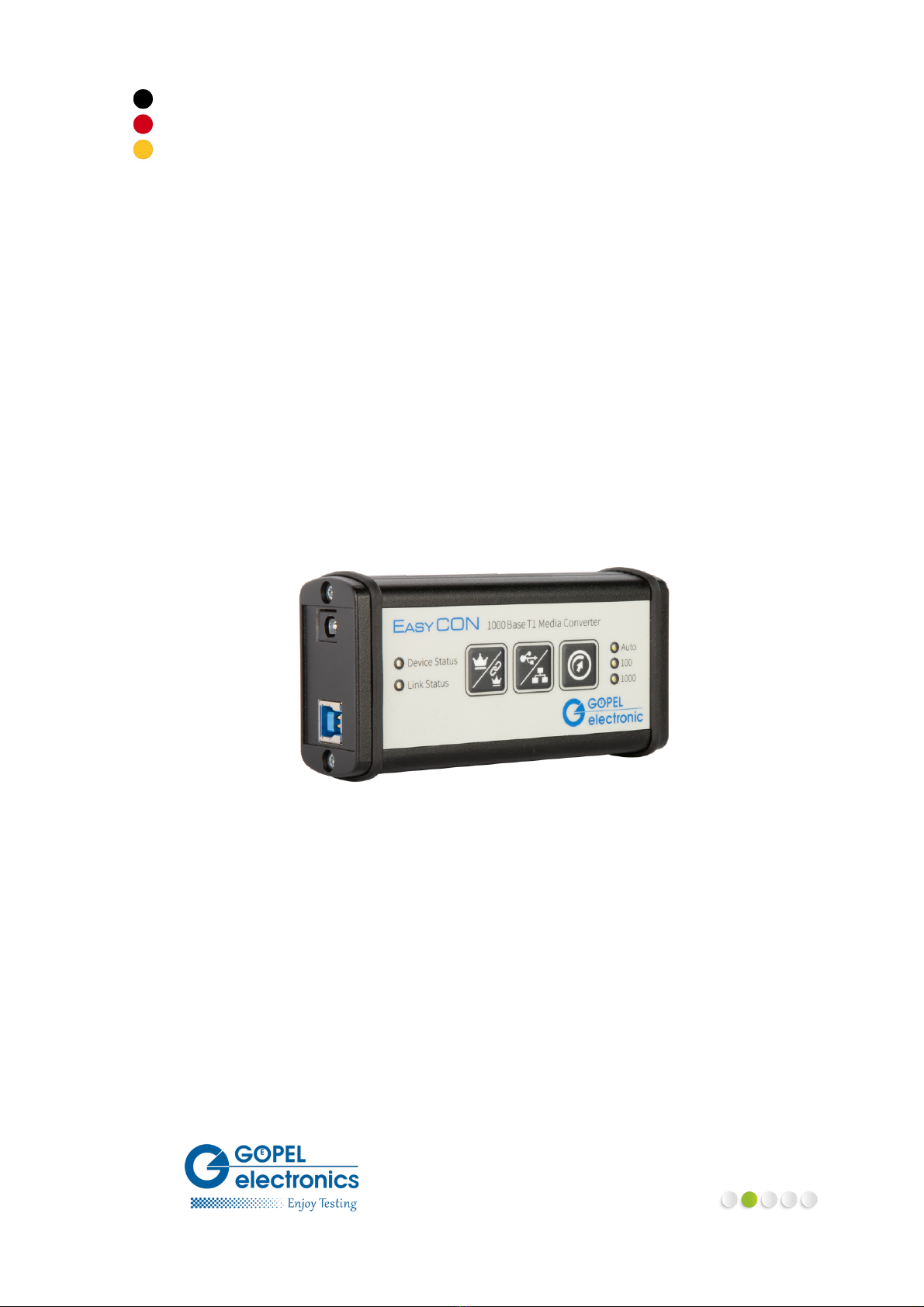
Easy CON - 1000Base-T1
iii
Table of Contents
1Introduction ................................................................................................................................ 1
1.1Notes on this Document ..................................................................................................... 1
1.2Intended Use .................................................................................................................... 1
1.3EMC Protection Measures .................................................................................................... 2
1.4EU Declaration of Conformity ............................................................................................... 2
1.5General Safety Regulations .................................................................................................. 2
1.6Liability and Warranty Exclusion ........................................................................................... 2
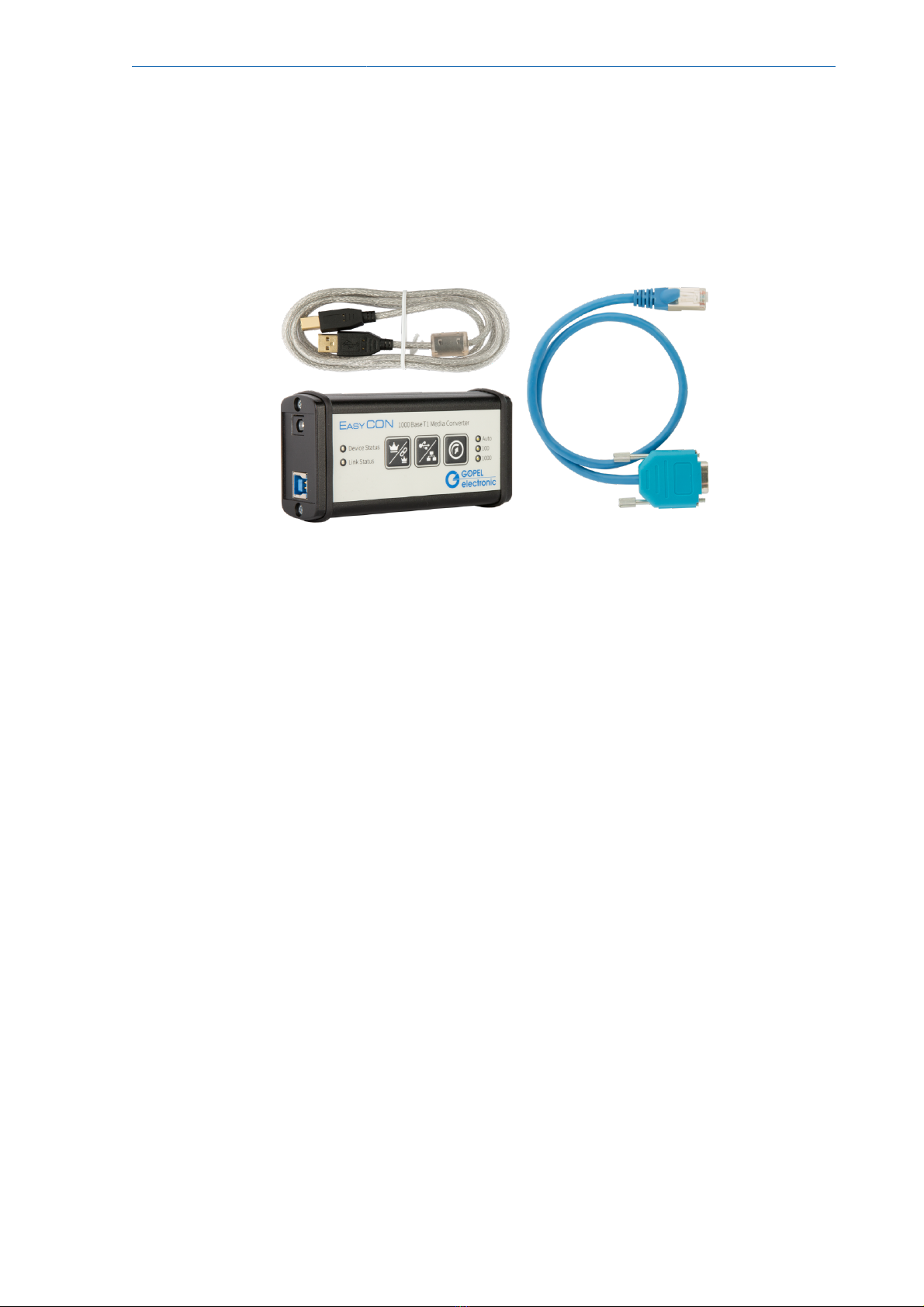
1.7Supplied Accessories .......................................................................................................... 3
2Technical Description .................................................................................................................... 4
2.1Overview .......................................................................................................................... 4
2.2Technical Specifications ...................................................................................................... 5
2.2.1Easy CON ............................................................................................................... 5
2.2.2Power Supply (optional) ........................................................................................... 5
2.3Interfaces ......................................................................................................................... 6
2.3.1Node 1 .................................................................................................................. 6
2.3.2Node 2 .................................................................................................................. 6
2.3.3Node 3 .................................................................................................................. 6
2.4Status Indication ............................................................................................................... 7
2.4.1Device Status LED .................................................................................................... 7
2.4.2Link Status LED ....................................................................................................... 7
2.4.3Ethernet Phy Status LEDs .......................................................................................... 7
2.4.4Automotive Ethernet Phy Status LEDs .......................................................................... 7
2.4.5Speed Mode LEDs .................................................................................................... 8
2.5Keypad ............................................................................................................................ 8
3Commissioning ............................................................................................................................ 9
3.1First Steps ........................................................................................................................ 9
3.2Driver Installation ............................................................................................................... 9
3.3Connections ...................................................................................................................... 9
3.4Legacy Mode - PHY compatibility mode ................................................................................. 9
4Service and Support .................................................................................................................... 10
4.1Spare Parts and Accessories ............................................................................................... 10
4.2Warranty and Repair ......................................................................................................... 11
4.2.1Conditions ............................................................................................................ 11
4.2.2Identification ......................................................................................................... 11
5Disposal .................................................................................................................................... 12
5.1Disposal of used Electrical / Electronic Equipment .................................................................. 12
5.2Disposal of used Disposable Batteries / Rechargeable Batteries ................................................. 12
Index .......................................................................................................................................... 13
AEU Declaration of Conformity ....................................................................................................... 14