Goldwing RC SBACH342 170CC V4 User manual

All contents copyright 2014, GoldWing RC Version 2.0, Feb 2014
GoldWing RC
SBACH342 170CC V4
Giant Scale Aerobatic Aircraft

All contents copyright 2014, GoldWing RC Version 2.0, Feb 2014
Specifications
Wing Span: 126"(3200mm)
Length: 121"(3070mm)
Wing Area: 2806sq in(181sq dm)
Flying Weight: 38.5-44lbs(17.3-20Kg)
Gas Engine: 150CC-230CC Gas DA150 DA170 DA200 DLE170 DLE222 GP176
Radio: 6+ Channels
Servos: 11-13 servos required 250 oz to 420 oz (15-25kg/cm)
JR 8911, Savox 1256
All contents copyright 2014, GoldWing RC
Version 2.0, Apr 2014
Dear Customer,
The latest Goldwing SBACH342 170CC V4 aircraft are designed in conjunction with EG AIRCRAFT. EG
Aircraft will be sold in the USA with other territories covered by Goldwing.
Specifications of the aircraft are identical between the brands.
The structure of the new EXTRA&SBACH 170CC V4 aircraft has been further optimized, retaining the
current features of being built super light for 3D aerobatics yet are even stronger. Designed for the latest
generation of high output engines like the DA-170\DA200\DLE170\DLE222.
Goldwing RC is always keeping the pace with the latest developments in aerobatic flight. The
EXTRA&SBACH has the following Improvements:
1. Bigger control services. Up to 60 degrees of throw on all control surfaces. Best for more vibrant
aerobatic flight.
2.Packed in strong honeycomb board cartoon. Better protection during transportation.
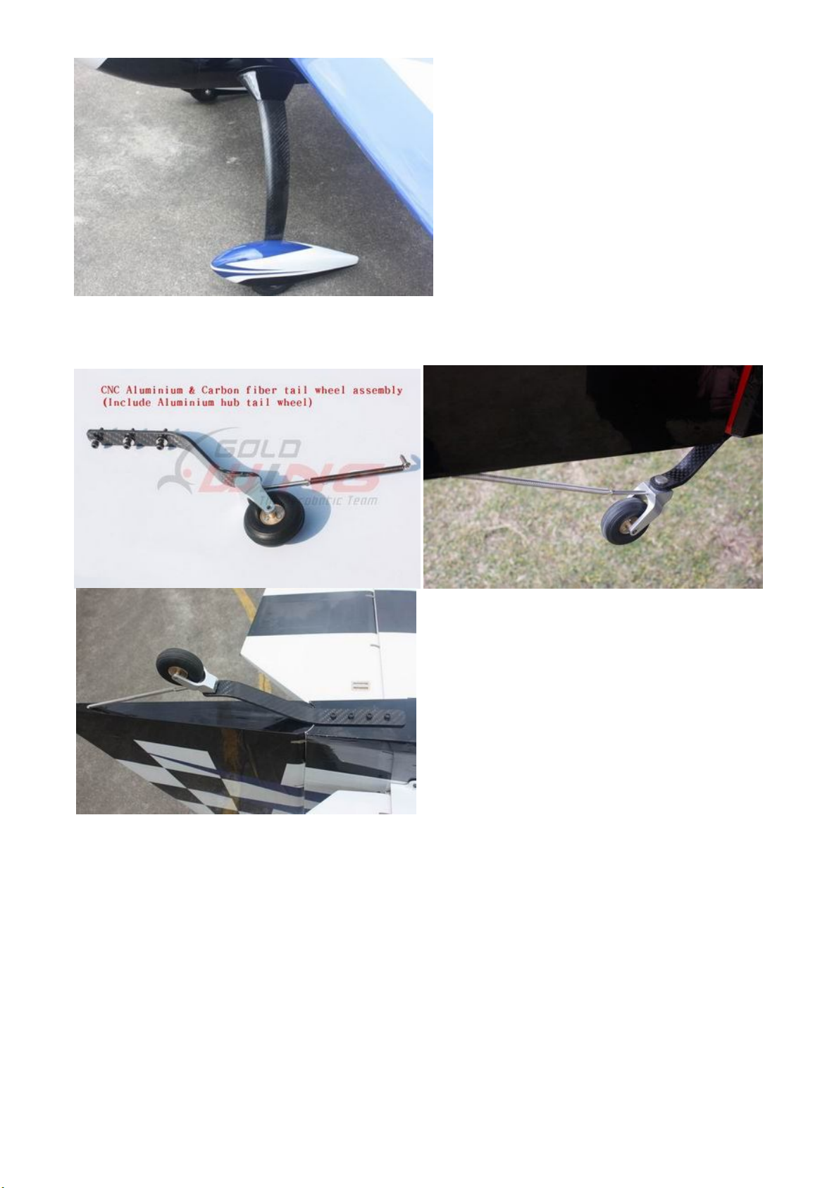
3.Improved carbon fiber tail wheel assembly, using CNC machined metal parts including aluminum tail
wheel hub.
4.Improved wheels with aluminum hub, built with more durable materials, and filled with rubber.
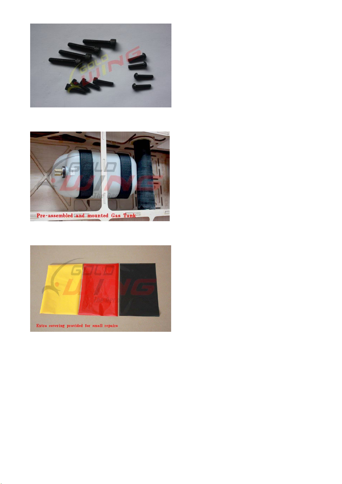
5.Using high quality cap head screws.
6.Spare covering included in the package. Convenient for repair.
7.Improved ball link assembly.
8.Upgraded to carbon fiber control horns.
9. Improved axles ,the material of the axle is stainless steel.
10. Include Side force generators.
11. Improved Pocket Style Scale Hinging.
12. This V4 new design with a longer fuselage moment arm aids the tracking of the model, giving it rock
sold precision flight. Making it perfect for modern day flight schedules for IMAC and Freestyle competitions.
A QUICK WORD ABOUT SAFETY AND RADIO CONTROL FLYING MODELS
With radio control aircraft, like any hobby or sport, there are certain risks. The operator of these models is
responsible for these risks. If misused or abused, you may cause serious bodily injury and/or damage to
property. With this in mind, you will want to be certain that you build your model carefully and correctly. If
you are not an experienced flier, have your work checked and ask for help in learning to fly safely. This model

All contents copyright 2014, GoldWing RC Version 2.0, Feb 2014
aircraft is not a toy and must be operated and flown in a safe manner at all times. Always perform a pre-flight
check of the model including all control surfaces, correct function of the radio gear, structure, radio range, and
any other area relating to the safe operation of this aircraft.
Models are not insurable but operators are. You can obtain coverage through membership in the Academy of
Model Aeronautics (AMA). For an AMA information package call 1-800-435-9262, ext. 292 or visit the AMA
website at "www.modelaircraft.org". Or if you are in any other country please contact the appropriate body.
By the act of using the final assembled model, the purchaser/operator accepts all resulting
liability.
Goldwing RC WARRANTY AND RETURN POLICY
GoldWing RC guarantees this product to be free from defects in both material and workmanship at the date of
purchase. This does not cover any parts damaged by use, misuse or modification. In no case shall liability
exceed the original cost of this kit. Because Goldwing RC has no control over the final assembly or
equipment/components used in the final assembly, no liability shall be assumed for any damage resulting from
the use of this model by the user. By the act of using the final assembled model, the user accepts all resulting
liability. If you should find any missing or damaged parts, or have any questions about this product, please
contact within 30 days of the purchase in order to be covered by our warranty. You may contact us at
service@goldwingrc.com.
Included Features:
Two piece clamshell cowl
Installed servo wire guide tube
Honeycomb board carton packing for safer transportation
Side force generators included
Fit new DA170 and GP176 Engines with more stronger design for fuselage and wings
Fixed ring inside cowling for easy build
Increased diameter carbon fiber wing tube over previous versions
All cowling and wheel pants used genuine epoxy resin
Pocket Style Scale Hinging

All contents copyright 2014, GoldWing RC Version 2.0, Feb 2014
Larger aileron and elevator design. Up to 60 degrees of throw on all control surfaces for excellent 3D
aerobatic flying
Adjustable pushrods for easy fine tuning(Includes wrench)

All contents copyright 2014, GoldWing RC Version 2.0, Feb 2014
High quality ball link assemblies
Aluminium hub rubber wheels
Replacement wheel tyres, using the existing wheel hubs.

All contents copyright 2014, GoldWing RC Version 2.0, Feb 2014
Improved axles (the material of the axle is now stainless steel )
Servo lead safety clips
High performance cap head bolts

All contents copyright 2014, GoldWing RC Version 2.0, Feb 2014
Pre-assembled and mounted gas tank
Extra covering provided for small repairs, genuine Ultracote / Oracover
Removable rudder

All contents copyright 2014, GoldWing RC Version 2.0, Feb 2014
CNC anodized aluminum canopy bolts
Full length tuned pipe design inside the fuselage
Carbon Fiber accessories version:
Extra strength carbon fiber control horns

All contents copyright 2014, GoldWing RC Version 2.0, Feb 2014
5in Painted carbon fiber spinner included
One piece air foiled carbon fiber landing gear

All contents copyright 2014, GoldWing RC Version 2.0, Feb 2014
Carbon fiber tail wheel assembly with CNC machined metal parts, including the aluminium tail wheel
hub.
Two Carbon fiber stab tube

All contents copyright 2014, GoldWing RC Version 2.0, Feb 2014
Items required to complete this Model:
150-230cc gas engine with stock or
aftermarket exhaust systems
Appropriate propeller for your engine
All the required engine and exhaust mounting
hardware
Ignition battery and switch
One quality throttle servo and appropriate
servo arm
8-10 high quality metal gear servos of 250 in-
oz
or better for the ailerons and elevators
Three high quality rudder servo of 420 in-oz or
better
Appropriate servo arms for the above
Heavy duty servo wire extensions.
Recommends four 72”, two 48”,one 24”, five 6-
12” extensions. Your installation though may
vary.
Two heavy duty switches with charging jacks
for the Rx
Two high quality Rx batteries of significant
capacity to power your choice of servos.
One receiver of your choice
Required Tools
Covering Iron and heat gun
Assortment normal hobby tools such as
screwdrivers, hobby knife, drill and drill bits,
pliers, etc.
Thick and thin CA adhesives
30 minute epoxy
Isopropyl alcohol
Ruler or tape measure
Blue thread-lock or equivalent
Note: As with all kits, it’s a good idea to read all the instructions and study the parts before you begin
construction. Handle the parts of this kit with care so you do not damage any of the structure or covering.
Inspect all the parts for any shipping damage and report any issues to as soon as you can. Make sure you
have a flat and sturdy workbench and follow all safety advice for the tools and adhesives you plan to use.
AIRCRAFT COVERING
1. With all ARFs, varying temperatures and storage delays can cause covering material to loosen over time
and transportation. We recommend lightly going over all the covering with a covering iron set at medium
temperatures. Be sure to use a soft cover over your iron so you do not scratch the covering surface. Be
sure you go over all seams and edges of the covering to assure it is secure to the airframe and other
covering. Be careful not to apply too much heat or you may cause bubbles or damage to the covering. A
heat gun may also be used along with a soft cotton cloth to shrink and adhere the covering. Again, be
extremely careful when using a heat gun.

All contents copyright 2014, GoldWing RC Version 2.0, Feb 2014
2. Be sure to seal any exposed wood with a thin coating of epoxy to prevent engine oil from soaking in. This
is especially important around the engine compartment and servo openings with exposed areas.
3. Some modelers prefer to seal the hinge gaps using strips of appropriate covering or clear trim tape. We
have found this to be helpful with models intended for higher speed flight or models with unusually large
hinge gaps. Our aircraft utilize a very tight double beveled hinge line and do not normally require this step.
Sealing the hinge gaps is therefore left as an option for the modeler.
Please verify the accessories before commencing assembly:
Carbon Fiber control Horns (Bag No. KA17CA) : 20 single horns for ailerons and elevator. 2 dual horns
for rudder.
Sand the area of the horn that will be glued to help adhesion.
Adjustable pushrods kits: (Bag No. KA17CB) Ten 3x60mm pushrods for ailerons & elevator. Three
3x40mm pushrods for rudder.Two 3x125mm pushrods rudder(Pull-push style)

All contents copyright 2014, GoldWing RC Version 2.0, Feb 2014
Pull-pull assembly kits for the rudder. (Bag No. KA17CD)
Ball link assembly (Bag No. KAG00133): 16 for ailerons and elevators.
Servo lead safety clips:10 pcs (Bag No. KAG0023)
4.5” Alu main wheels:2pcs(Bag No. KAG015C)

All contents copyright 2014, GoldWing RC Version 2.0, Feb 2014
New stainless steel Axle kits (Bag No. KA17CH)
Carbon fibre tail wheel assembly with CNC machined metal parts, including the aluminium tail wheel
hub. (Bag No. KAGC106)
Extra covering provided for small repairs
Bolts for landing gear: 4(6x26mm) hex bolts & 4 washers & 4(M6) stainless steel self-locking nuts

All contents copyright 2014, GoldWing RC Version 2.0, Feb 2014
Bolts & washers for cowl: 9(3x16mm) Hexagon bolts and 4 washers
Spares bag(Four spare aluminum hand-twist bolts \ Four spare wing bolts\One spare tail wheel spring)
RUDDER ASSEMBLY
NOTE: There are pictures of different planes in this manual, however, this plane’s rudder is assembled the
same way.
1.It is much easier to install the twin control horns before installing the rudder. Locate the carbon fiber
rudder control horns, ball links, and associated bolts and nylon-insert lock nuts. Use some fine sandpaper
to roughen up the center areas of the two control horns so that the glue adheres better. Using a sharp
hobby knife or soldering iron remove the covering away from the slots in the rudder and trial fit the two
control horns.
2. Mix up some 30 minute epoxy and coat the inside of the slots and the center of the control horns. Hint: a
scrap piece of 1/16” ply, tooth pick, or old hobby blade can be used to coat the inside of the rudder slots.
Slide the control horns in place and make sure they are centered perfectly by using a ruler to measure
between the pivot holes and the hinge line. Wipe any excess glue off with isopropyl alcohol and paper
towels. Install the ball links, bolts and nuts into the holes to help assure alignment of both control horns
while the glue cures. Set aside until cured. NOTE: There are pictures of different planes in this manual;
however, this plane’s rudder is assembled the same way.

All contents copyright 2014, GoldWing RC Version 2.0, Feb 2014
3.To fit the rudder to the fin, locate the rudder hinge wire and insert. To make it easier to insert twist as it is
inserted.
4. The EXTRA&SBACH can use either closed loop or a rear push pull servo for the rudder. We recommend that
you balance the model assembled before choosing your servo placement.

All contents copyright 2014, GoldWing RC Version 2.0, Feb 2014
5. The EXTRA&SBACH is supplied with a high quality set of pull-pull cables and ball-links.
6. Install your rudder servo into the precut locations in the fuselage. Using a fine drill pre-drill the holes and
drop thin CA into the holes to strengthen the wood. You will need 3 inch arms on the servo. Set up your radio
accordingly and center the rudder servo.
7.We recommend using KUZA CNC servo arms (sold separately) for rudder control. 2PCS 3.25” Dual
arm,1PCS 4.75” Dual arm
8. The EXTRA&SBACH has the closed loop pre-installed and crimped at the rudder end. These can be
connected with the M3 bolt and nut. The wire will be left looped inside the fuselage and will need to be
connected to the servo arm.

All contents copyright 2014, GoldWing RC Version 2.0, Feb 2014
9. Use your radio system to center the rudder servo and attach either the supplied arm or an appropriate arm
for your servo. Thread one of the ball links about half way onto one of the threaded couplers. Feed the loose
end of one of the cables through a brass tube and then through the threaded coupler. Holding the rudder
centered, adjust the cable length as tight as possible while checking the ball link position over the servo arm.
When satisfied with the position, pinch the cable around the threaded coupler and then feed the loose end
back through the brass tube. Loop the cable back through the brass tube as before and crimp the brass tube
three times just tight enough not to cut the brass tube but enough to securely hold the wire in place. Cut off
the excess cable with wire cutters. Wick thin CA into the brass tube to help hold the cable secure. Repeat for
the other cable. Hint: Once you have established the position of the threaded coupler on the cable, you can
remove the ball link from the rudder horn to give you more working slack in the fuselage. Re-install the ball
link prior to setting the other cable.
10. You can inchoose KUZA rudder servo tray assembly(sold separately). Include 1PCS servo tray ,3PCS 3.25”
Dual arm.

All contents copyright 2014, GoldWing RC Version 2.0, Feb 2014

All contents copyright 2014, GoldWing RC Version 2.0, Feb 2014
11.The EXTRA&SBACH also provides pull-push style for rudder.
12. Cut off excess carbon fiber rudder horn, and use sandpaper to rough the parts needed to inlay, and use
epoxy glue to glue the horn in place.
Table of contents