GOLEM Instruments Jupiter 4 User manual

1
Manual
Theremin Jupiter 4
Stand : NOV 2013 (V1.00-GB)

2
The delivery consists of:
1 x Theremin - Modell Jupiter 4
1 x Rod Antenna with Safety-Ball
1 x Volume-Antenna
1 x Power Adapter 12V / 300 mA
The Theremin is delivered ready for operation and calibration.
The Theremin is designed for connection to an amplifier. The height output level of about
0.6 VSS provides a good signal / noise ratio.
The amplifier characteristics affect the sound of the instrument, as it is also with other
instruments. But basically any audio amplifier with a max. Input level of about 1.0 VSS is
suitable. This property is practically given at all amplifiers for musical applications. In
order to reproduce the full range of the Theremin can, the amplifier should play sounds
in the lower frequency spectrum (<= 100 Hz) well.
Most amplifiers are coupled to ground potential. I.e. occurs the mass of the input /
output is on the ground potential of the power supply. It also amplifiers are offered in
which there is a potential separation. The use of this amplifiers is not recommended.
The connection to the amplifier is done through a so-called guitar cable. This cable has a
jack plug at both ends 6.3 mm (mono).
If your amplifier has a different audio input jack, use a suitable cable accordingly or else
an adapter (for example, 6.3 mm jack to 3.5 mm jack).
A connection to the sound card of your computer is also possible. Connect here the
Theremin and the audio input of the computer conveniently via a guitar cable with an
appropriate adapter.
Amplifer connection
Package

3
The Theremin is played by the approach and distance of the player's hand. To further the
hand is removed from the antenna, to quieter the sound. The volume control is done via
the curved antenna of the theremin.
The play area of Jupiter model includes a frequency spectrum from about 50/100 -1800
Hz (corresponding to about 4 octaves). The upper frequency is a fixed value which can
not be exceeded. This frequency will already reached about 0.5 cm in front of the
antenna. In the range 0-ca. 0.5 cm the frequency is changed no more. This allows a
better play even in the uppermost frequency range.
The decisive factor in the development was also a good playability in the preferred range
at 1 kHz. The Jupiter model has been implemented a good frequency / distance
relationship. By slightly moving the finger at constant tone, a clean pitch shifting effect
can be achieved.
The Sensitivity parameter controls the gain of the antenna signal. This may lead to a
slight gain depending on "chatter" sound at low frequencies.
The characteristic of the Attenuator is expotenziell. I.e. at a distance of about 30 cm - 10
cm, the volume is 100% - 50%. At a distance of about 10 - 5 cm, the volume is
controlled down to approximately about 50% 1-0% .
Is the hand in the range of about 5 - 0 cm above the antenna, the volume is governed
to the minimum. This type of control allows a soft gentle volume control at the top and at
the bottom of a fast, but still sliding, and hide the sound. Direct contact of the volume
antenna no longer changes the volume.
You can turn on the Theremin by the sensitivity switch. Is the theremin turned on, the
yellow control LED "On" lights.
At antenna controlled Theremines, the physical property is used to detect a change in
capacitance between the antenna and the hand of the player. Because these changes are
very small in practice, numerous factors can influence the result of the electronic
evaluation. This includes in particular the heating of the electronic components of the
Theremin.
Therefore, turn the Theremin on, 10 minutes before the game starts, to bring it up to
operating temperature. The case of the Theremin warms up only marginally. The same
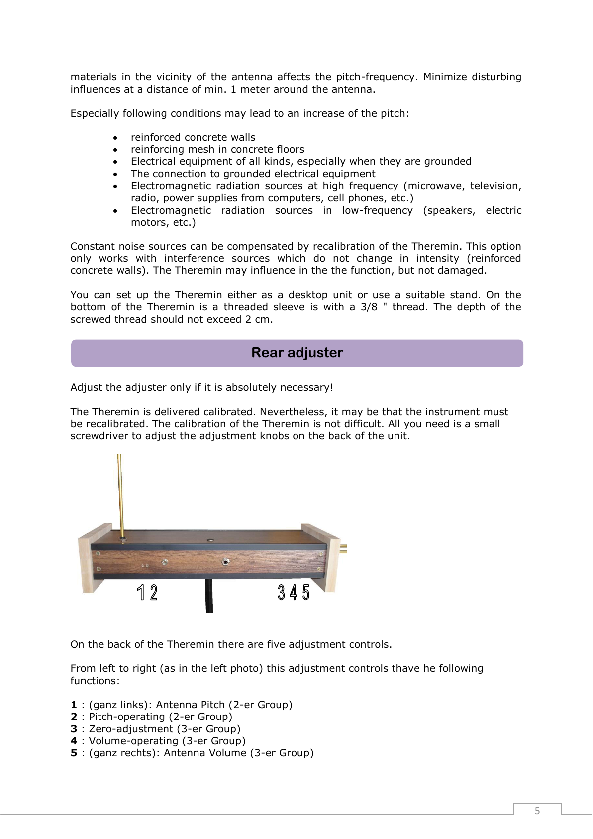
Activation oft he Theremin
Distance-regulator
Sensitivity-regulator
Pitch-regulator
Device-properties

4
applies if you choose, for example, in a location in direct sunlight or go with the Theremin
from a cold to a heated room.
The Theremin is used to power the connection of a mains adapter (12V DC). Whenever
possible, use only the supplied AC adapter. Change down the Theremin and connect the
power supply to the jack on the rear panel.
The device has an internal reverse protection. If the AC adapter has a polarity switch,
this is all the same. This Theremin is protected from accidental damage by accidental
wrong input.
Should the power supply thave a switch to adjust the output voltage, set it on the item
labeled 12V.
Unwanted changes this switch can possibly lead to a malfunction of the Theremin - but
damaged this not. Put the switch just in the right position.
The effective length of the pitch antenna is about 50 cm. The diameter is 6 mm.
The antenna connection in the case of the Theremin consists of a 6 mm socket. The
antenna can be drawn out for transport. The antenna must fit easily into the socket.
Encounter when inserting the antenna to greater resistance, changing the insertion angle
slightly. Do not use violence, otherwise it could lead to a bending of the socket contacts!
A slightly rotation of the antenna during insertion facilitates insertion. Slide the antenna
until the beginning of the black mark in the socket.
Using a 6 mm socket allows you to experiment with own antennas. The shape of the
antenna has an effect on the sensitivity of the pitch-control.
Make sure that the ball is always on the antenna. This has no effect on the technical
characteristics of the Theremin, but is in addition to the visual enhancement also for your
protection. The antenna end is approximately at eye level!
The volume antenna consists of a specially curved brass tube. Insert it to the black
marks in the sockets provided for in the left part of the Theremin. The insertion depth is
about 3 cm. There exists a stop. Push the two ends simultaneously in the two antenna
connectors - possibly with a simultaneous slight turning. Do not use force!
The functioning of each Theremins substantiated in an electronic measurement and
evaluation of the capacitance between the antenna and the hand of the player. But not
only the player's hand affects the pitch of the Theremin. All electrically conductive
Installation
Volume-Antenna
Pitch-Antenna
Power

5
materials in the vicinity of the antenna affects the pitch-frequency. Minimize disturbing
influences at a distance of min. 1 meter around the antenna.
Especially following conditions may lead to an increase of the pitch:
reinforced concrete walls
reinforcing mesh in concrete floors
Electrical equipment of all kinds, especially when they are grounded
The connection to grounded electrical equipment
Electromagnetic radiation sources at high frequency (microwave, television,
radio, power supplies from computers, cell phones, etc.)
Electromagnetic radiation sources in low-frequency (speakers, electric
motors, etc.)
Constant noise sources can be compensated by recalibration of the Theremin. This option
only works with interference sources which do not change in intensity (reinforced
concrete walls). The Theremin may influence in the the function, but not damaged.
You can set up the Theremin either as a desktop unit or use a suitable stand. On the
bottom of the Theremin is a threaded sleeve is with a 3/8 " thread. The depth of the
screwed thread should not exceed 2 cm.
Adjust the adjuster only if it is absolutely necessary!
The Theremin is delivered calibrated. Nevertheless, it may be that the instrument must
be recalibrated. The calibration of the Theremin is not difficult. All you need is a small
screwdriver to adjust the adjustment knobs on the back of the unit.
On the back of the Theremin there are five adjustment controls.
From left to right (as in the left photo) this adjustment controls thave he following
functions:
1: (ganz links): Antenna Pitch (2-er Group)
2 : Pitch-operating (2-er Group)
3: Zero-adjustment (3-er Group)
4: Volume-operating (3-er Group)
5: (ganz rechts): Antenna Volume (3-er Group)
Rear adjuster

6
The adjuster 2 has the same function as the pitch-regulator on the front of the Theremin.
If the control range of the pitch- control is not sufficient to take a desired setting, use the
adjuster 2 on the back of the Theremin. Before adjusting the control- regulator, take the
knob on the front to a central position. Now you can make with the adjusting 2 a rough
adjustment and then a fine adjustment with the pitch-knob on the frontside.
That's how to proceed in case of need with the adjusting 4 when the control range of the
volume-knob on the front of the device is no longer sufficient.
The controls for 1 and 5 are used for antenna adjustment and should not be changed!
With adjustment 3 you can set the minimum volume by occupied volume antenna.
All adjuster have a range of 25 turns and can be adjusted with a small screwdriver. The
adjuster have no stop on both sides - but can not be "turned on".
Clean the case only with a dry cloth or brush. Do not use a wet care!
The antennas are made of polished brass. This material does have a fine golden luster,
but it goes on the air in dark especially when combined with fat. This effect can not be
avoided. If you want to clean the antenna, so you can pull it out of the socket, remove
the ball for cleaning and common household cleaners (Stahlfix, chrome polish, scouring
soap, etc.).
Before reinserting the antennas they should be well dried (also inside - pipe!).
Case dimensions: ca. 430 x 160 x 100 mm (whithout Antenna)
Antenna connector: Buchse 6 mm (Pitch), 2 x Buchse 6 mm (Volume)
Antenna length: 50 cm (Pitch), 30 x 15 cm (Volume)
Weight: ca. 1500 g
Current consumption: ca. 85 mA
Frequency range: ca. 50/100 Hz –ca. 2800 Hz (~ 4-5 Oktaven)
Output: Jack 6,3 mm (Mono)
Output signal: up to appr. 0,8 VSS - over the complete Frequency range
constant (Sinus)
Technical Futures
Care and cleaning
Calibration

7
The connection of external devices (amplifiers, etc.) are at your own risk and
liability.
When operating, a Theremin produces a RF radiation. For safety reasons
persons with cardiac pacemakers should not use a Theremin!
© Copyright by Fritz Soll / GOLEM-instruments (2013)
Warning
Table of contents