PSM-SERIES PROGRAMMABLE POWER SUPPLY
USER MANUAL
⎯⎯
9
15. DELAY Set the voltage and current output time in the
automatic operation mode.
16. AUTO RANGE
(AUTO INFO)
Proceed setting step by step. During setting
proceeding, press this key can display the
memory address of the setting and its residual
time and period (The secondary function key).
17. AUTO Turn ON/OFF the auto operation.
18. RECALL
Recall one of the memory datas (The secondary
function key).
When query the memory setting data, in
order to avoid personal injury and damaging
the machine, it is suggested to disconnect the
output.
19. STORE Store the data to one of the memory groups
(The secondary function key).
20. SHIFT Select the secondary function key.
21. “0”, “1”… “9”, “.” The key for number input.
22. ENTER The key for Input confirmation.
23. LOCAL Clear the remote control mode by using the
panel control setting instead.
24. GPIB/RS-232 Select GPIB or RS-232 by pressing [SHIFT]
[GPIB/RS-232].
V STEP Voltage Step setting (The secondary function
key).
25. I STEP Current Step setting (The secondary function
key).
I△Under the status of [SHIFT], press I△to
ascend one step of output current value.
I▽Under the status of [SHIFT], press I▽to
descend one step of output current value.
V△Under the status of [SHIFT], press V△to
ascend one step of output voltage value.
26.
V▽Under the status of [SHIFT], press V▽to
descend one step of output voltage value.
PSM-SERIES PROGRAMMABLE POWER SUPPLY
USER MANUAL
⎯⎯
10
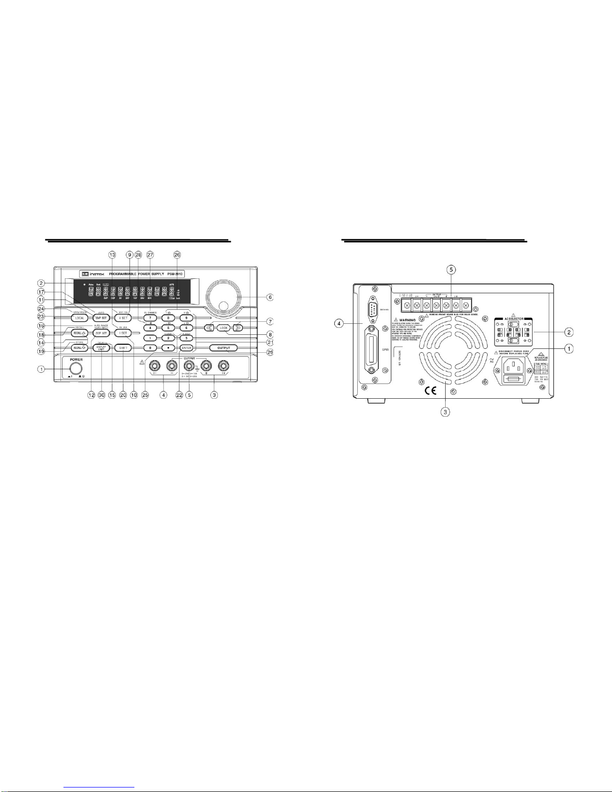
27. FL DIMMER
Adjust the intensity of VFD. After pressing
[SHIFT], can press [FL DIMMER] continually
until the required brightness is reached. Then
press again the [SHIFT] to end the setting.
28. Set beeper by pressing [SHIFT][ ] to turn
ON/OFF the buzzer.
29. OUTPUT Turn on or off output by pressing the knob.
30. DISPLAY LIMIT
Switch over the voltage and current mode by
pressing [DISPLAY LIMIT].
The setting value will be displayed, press again
[DISPLAY LIMIT] or wait a few seconds to
return to the previous status.
4-2. Rear Panel brief
1. AC Power Socket AC power input terminal.
2. AC Select Switch Switch Voltage to 100V, 120V, 220V or 230V,
50/60Hz.
3. Cooling Fan A cooling fan.
4. Interface GPIB or RS-232 communication interface.
5. Output Terminal The output terminals of rear panel connected
with case, including output sampling terminal
and ground terminal.