55
Informationen zum Handbuch
Die Geräte DPS-200A, 500A, 500DC und 700 von
D-Link sind redundante, zur Installation in einem
Standardrack ausgelegte Stromversorgungsgeräte
(RPS) und kostengünstige Quellen zur Bereitstellung
ununterbrochener Stromversorgung. Dieser
Leitfaden bietet Ihnen schrittweise durchzuführende
Anleitungen zur Einrichtung der Modelle
DPS-200A, 500A, 500DC und 700 mit einem Switch,
der die Stromzufuhr über ein 14-Pin oder 22-Pin
Gleichstromkabel unterstützt. Bitte beachten Sie,
dass Ihr Modell sich möglicherweise geringfügig von
den Abbildungen unterscheidet.
Nähere Informationen über Ihren Switch und
seine Komponenten sowie zur Herstellung von
Netzwerkverbindungen und zu den entsprechenden
technischen Daten nden Sie im Benutzerhandbuch,
das Ihrem Switch beiliegt.
Einführung
Eine redundante Stromversorgung bietet eine
kostengünstige und einfache Lösung auf das ebenso
einfache, aber leidige Problem eines internen
Stromausfalls, der zum Abschalten eines einzelnen
Schaltgeräts oder zum Ausfall eines gesamten
Netzwerks führen kann.
Durch den Anschluss einer redundanten
Stromversorgung wird die interne
Stromversorgung des Switch durch eine integrierte
Schaltkreiserkennung ununterbrochen überwacht.
Kommt es zum Ausfall der Stromversorgung,
löst dieseer Vorgang sofort ein Einschalten der
redundanten Stromzufuhr aus, sodass der Switch
und die angeschlossenen Geräte ihre Dienste
weiterhin bereitstellen können.
Ergebnis ist eine zuverlässigere
Netzwerkinfrastruktur, die das Netzwerk vor einem
Ausfall der Stromversorgung eines einzelnen
Netzgeräts schützt.
Beschreibung
Der DPS-200A, DPS-500A, DPS-500DC und
700 sind redundante Stromversorgungsgeräte,
die so ausgelegt sind, dass sie den
Wattleistungsanforderungen der Switches
entsprechen.
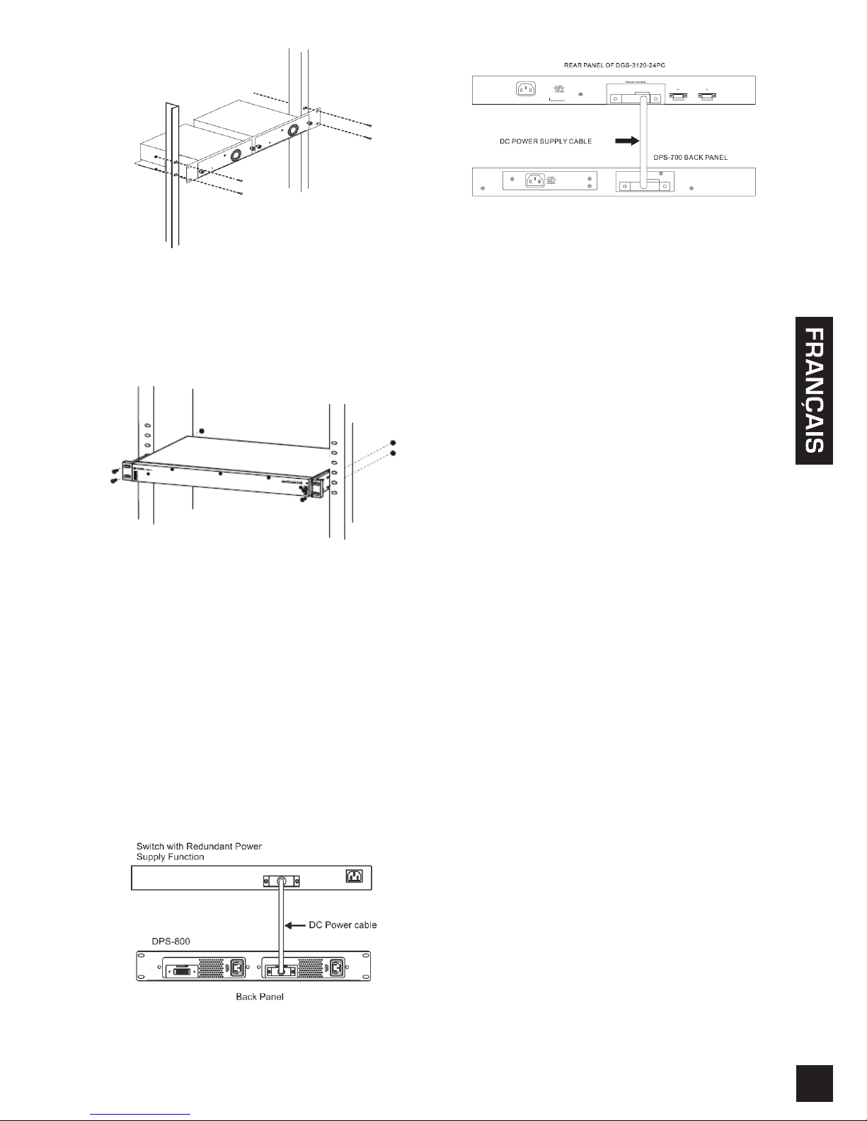
Das DPS-200A, DPS-500A und das DPS-500DC
können mithilfe eines 14-Pin Gleichstromkabels an
den Master Switch angeschlossen werden. Für das
DPS-700 wird dagegen ein 22-Pin Gleichstromkabel
verwendet. Ein standardmäßiger Schuko-Stecker
verbindet die redundante Stromversorgung mit der
Hauptstromquelle.
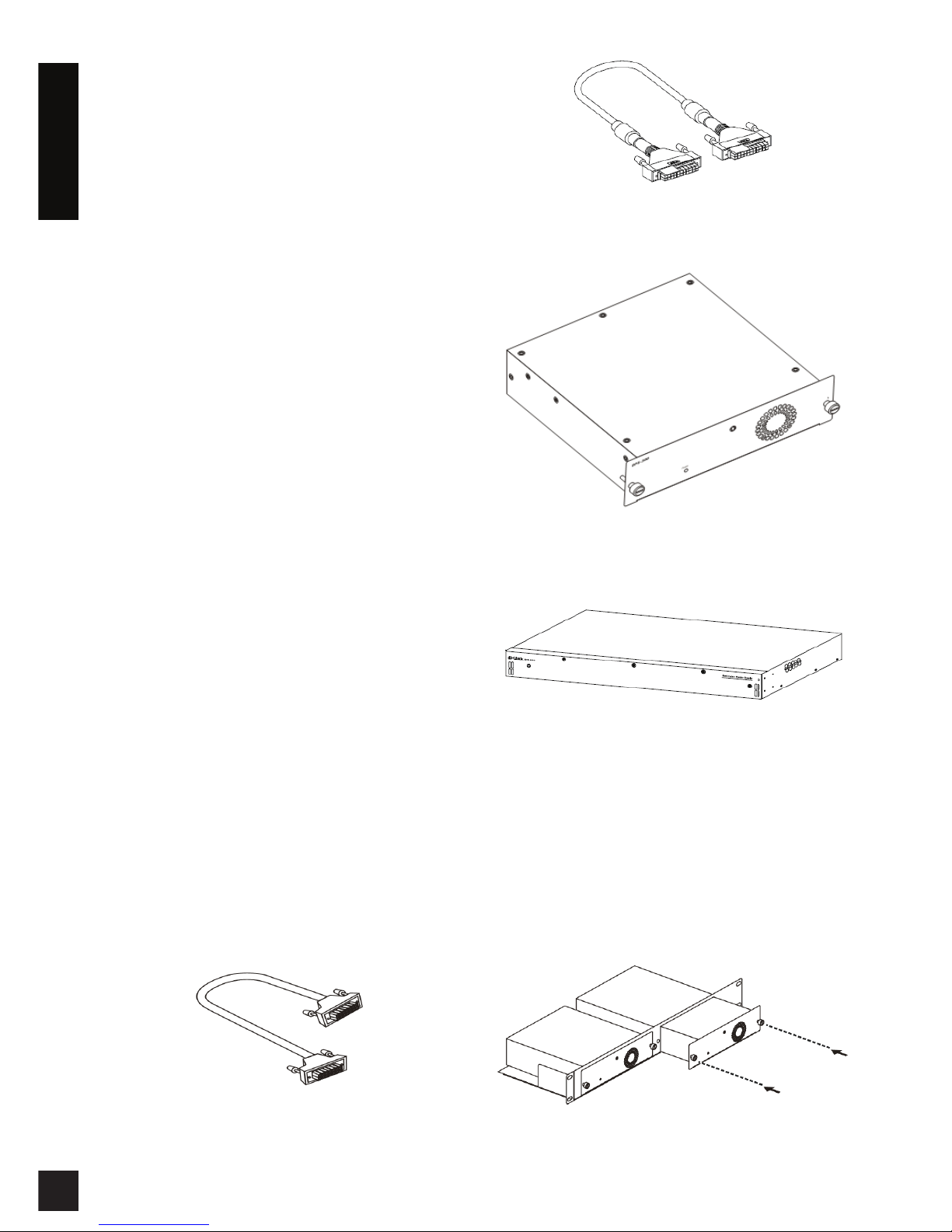
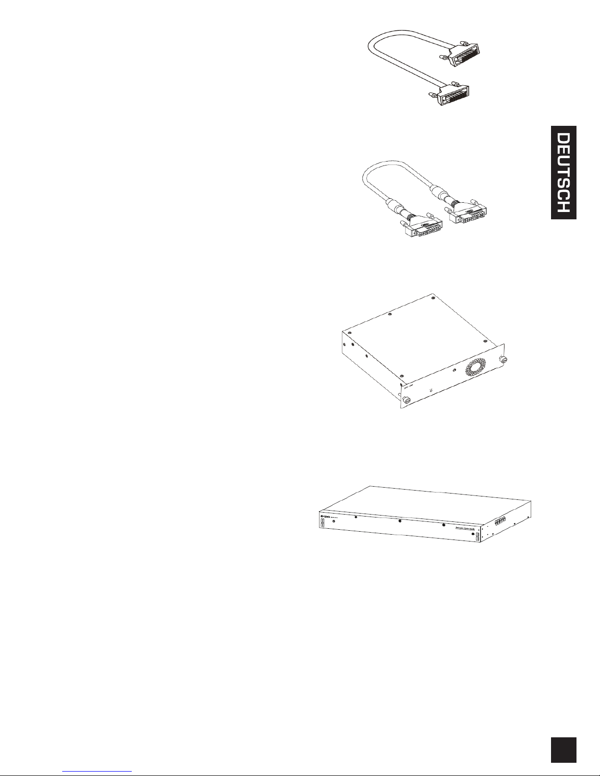
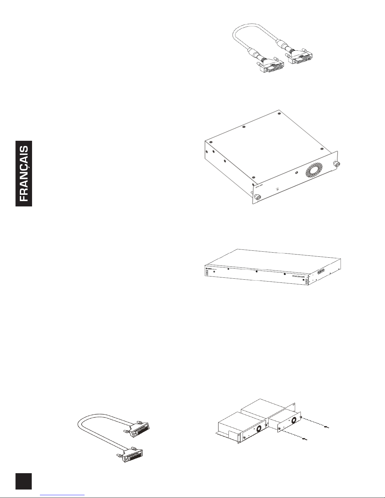
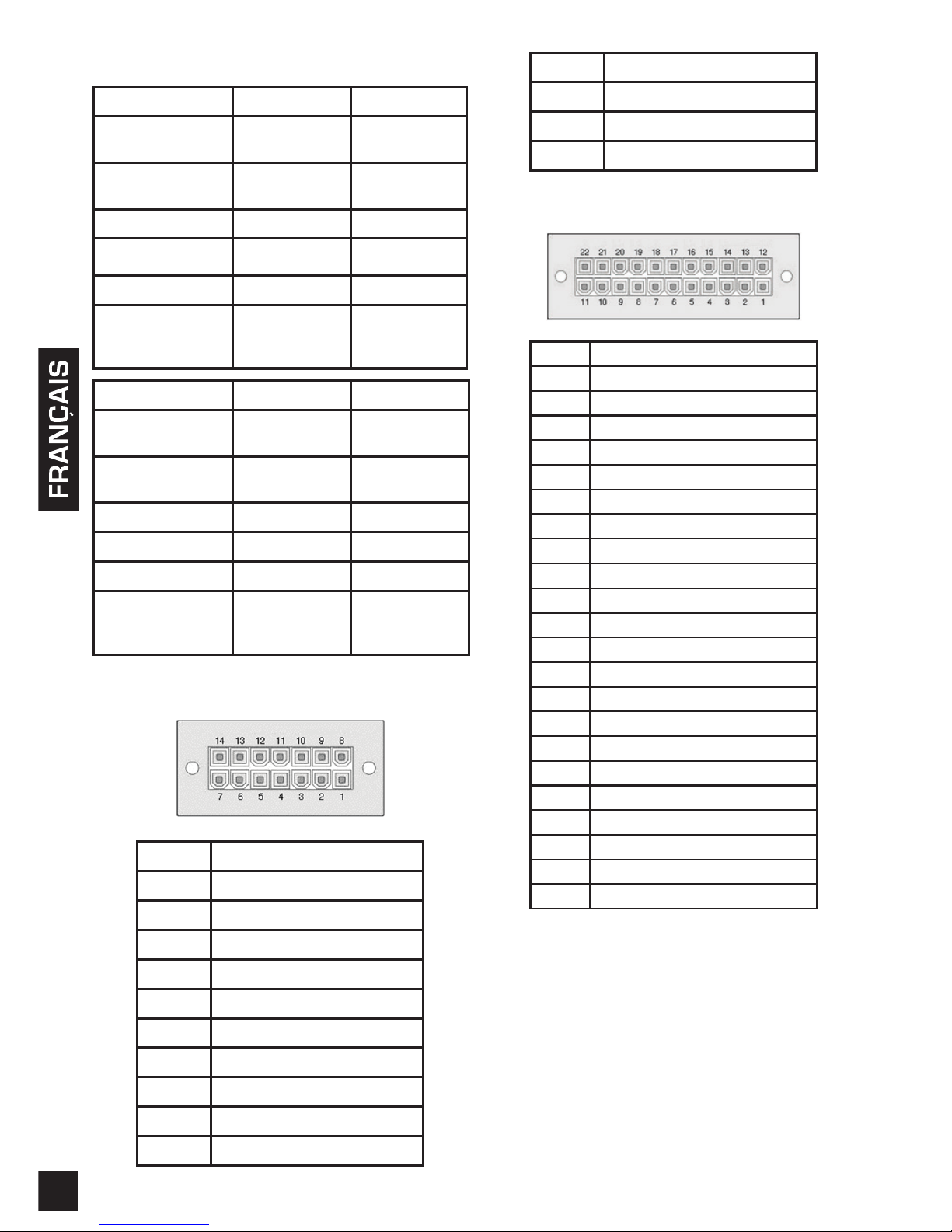
14-Pin Gleichstromkabel
22-pin Gleichstromkabel
RPS (Redundantes Einzelnetzteil (DPS-200A /DPS-
500A/DPS-500DC)
RPS (Redundantes Einzelnetzteil (DPS-700))
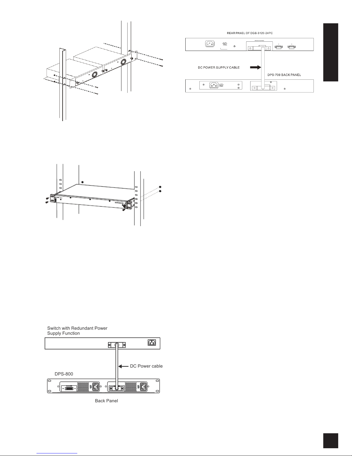
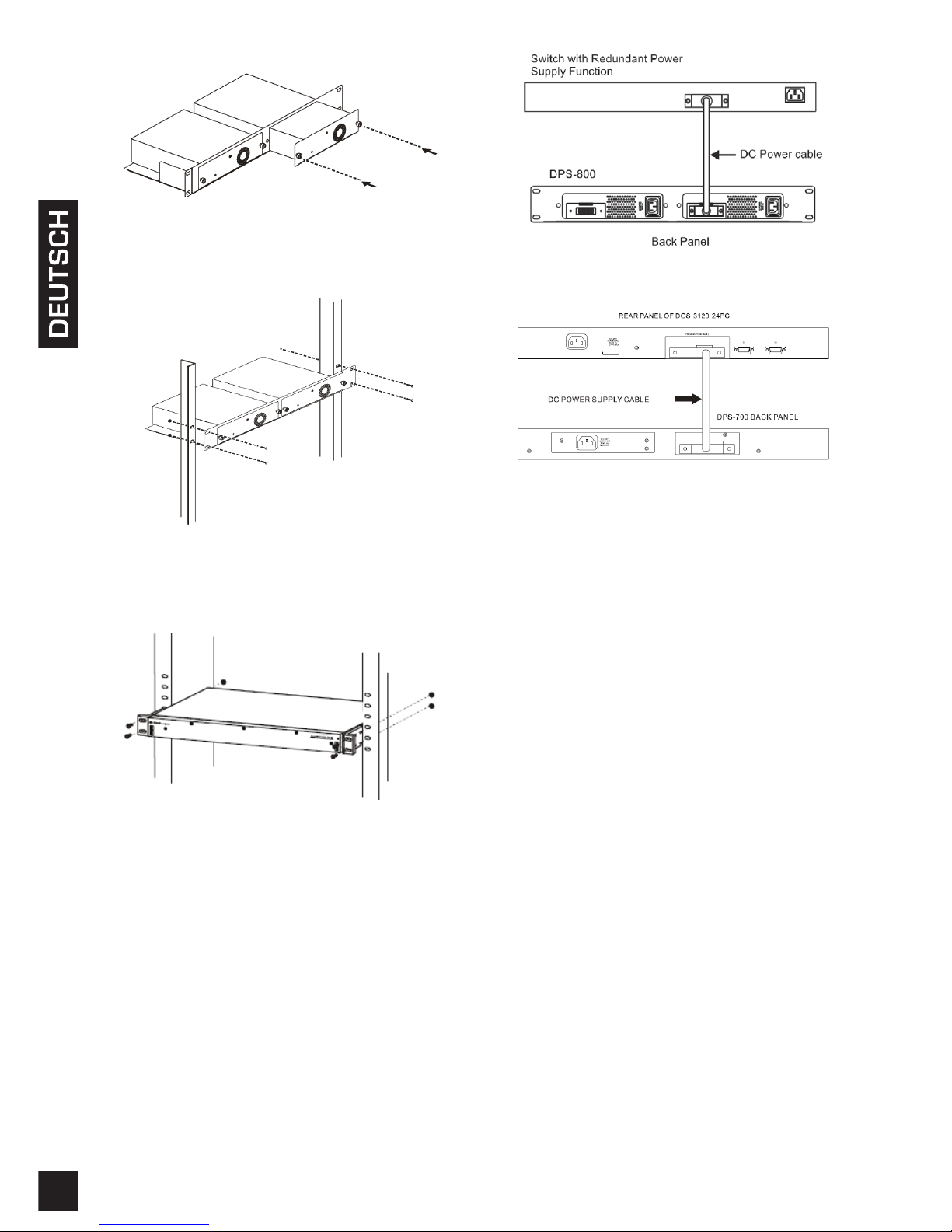
Rackmontage
Das einzelne RPS DPS-200A, 500A und 500DC
kann im Standardrack über das RPS Rack DPS-800
installiert werden. Bei dem DPS-800 handelt es sich
um ein für 2 redundante Stromversorgungseinheiten
entwickeltes Rack-Montagegehäuse (1 HE
(Höheneinheit/44,45 mm). Für die Installation
geeignete RPS-Geräte können DPS-200As, DPS-
500As, DPS-500DCs oder eine Kombination dieser
Geräte sein.