G-Series Automatic On/O Timer Instruction Manual
Setting The Operating Time
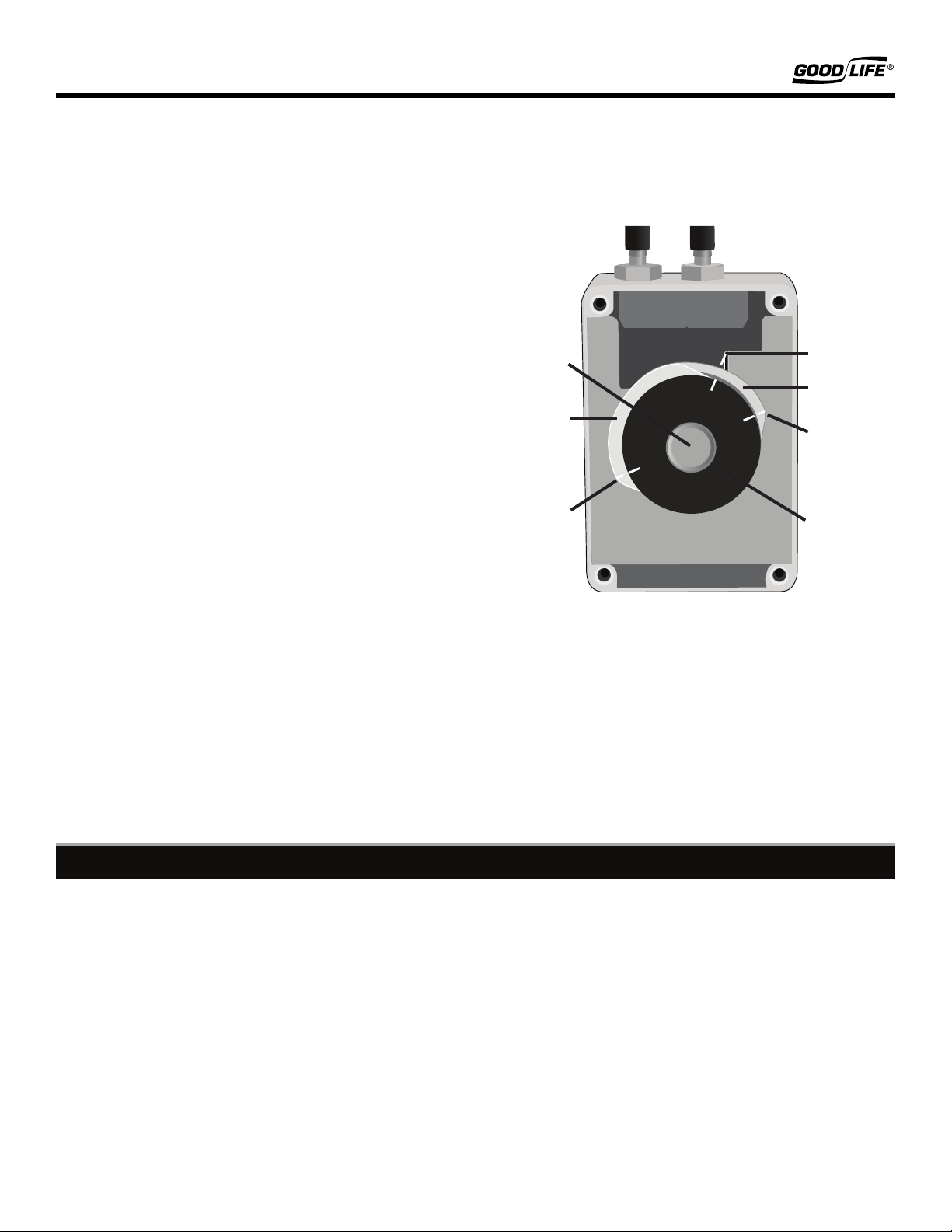
The Timer Unit is composed of 4 parts:
1. The Milled Nut: loosens and tightens in order to adjust the
timing settings.
2. The 24-hour Timer: Used to set time of day and timing
interval for cannon operation.
3. The Upper Cam Disc: Selects start time of cannon
operation.
4. The Lower Cam Disc: Selects stop time of cannon
operation.
NOTE:The upper and lower cam discs open the gas valve by
raising the internal lever as the timer unit rotates. When the
cam discs are in the ‘o’ position, a space of 3/8” to 5/8” should
been seen between the lever and cam discs. Lowering the lever
stops the gas ow.
Hold the timer unit still to loosen the milled nut. Align the
24-hour Timer so that the actual time of day points to the time
indicator line located to the upper right of the drive unit.
NOTE: The timer is based on military time. For example, “15”
corresponds to 3:00pm.
Turn the upper cam disc (just beneath the 24-hour timer) so
that the left corner peak corresponds to the required starting
time (start), and turn the lower cam disc so that the end (right)
corner corresponds to the required end time (stop).
Once the operating time is set, tighten the milled nut while
holding the timer unit in place. Flip the drive unit over
and insert it back into the housing unit so that the battery
compartment is facing outward.
Place the front cover back on the housing unit. Ensure the
screws are properly tted and that the cover and housing are
tightly sealed to prevent moisture from entering the housing.
Open the valve on the propane tank. The timer will now
operate automatically.
Store the timer in a dry and dust-free location when not in use.
For long-term storage, remove the battery and protect the gas
ttings by placing the caps back on each tting. Install a new
battery at the beginning of each operating season.
In the above example, the current time is 3:00pm. The number 15 on
the 24-hour timer points to the current time indicator.
The cannon is set to operate between 6:00am and 6:00pm, as set by
the upper and lower cam discs. The starting point, or left corner, of
the upper cam disc points to the digit 6 on the 24-hour timer. The
end point, or right corner, of the lower cam disc points to the digit
18 on the 24-hour timer.
Note that the cam discs create a continuous raised edge that
will manually raise the internal lever to allow gas ow.
15
18
6
More Details
Toll Free: 1-800-657-8214
Outside US: 1-541-245-4488
Website:
pestrepellerultimate.com
Email:
We’re Here to Help
Contact Us
Don’t worry, we’ve got you covered! Your cannon is backed by our 1-Year Manufacturer’s Warranty, which protects against
any defects due to manufacturing. For more information, go to pestrepellerultimate.com/pages/warranty. Please visit
pestrepellerultimate.com and start a chat with one of our friendly customer service agents, or contact us using the information
below.
Time
Indicator
Lower
Cam Disc
Upper
Cam Disc
Milled
Nut
Start Time
End Time
24-hour
Timer


