Goodmans GCE 7350 MP3R User manual

INSTRUCTION
MANUAL
Model GCE 7350 MP3R
In Car RDS Radio
Compact Disc Player
022475

Goodmans Product Information Helpline (02392) 391100
Installation Helpline (01132) 868613
P. 2
MULTIPATH DISTORTION / MUTING
Please note: An integrally mounted screen aerial may give rise to increase multipath
distortion or spurious muting of the audio output. This is normal and to be expected.
The use of an externally mounted rod aerial may reduce or possibly eliminate such
problems.
Most screen aerials require a 12 volt supply to operate correctly. Please check that this
has been connected to the +12 volt antenna wire of your radio. If you are in any doubt
of this connection please contact the vehicle dealer or Goodmans installation helpline.
CONTENTS
Accessories...................................................................................................Page 3
Important Notes ............................................................................................Page 4
Precautions and Maintenance ......................................................................Page 5
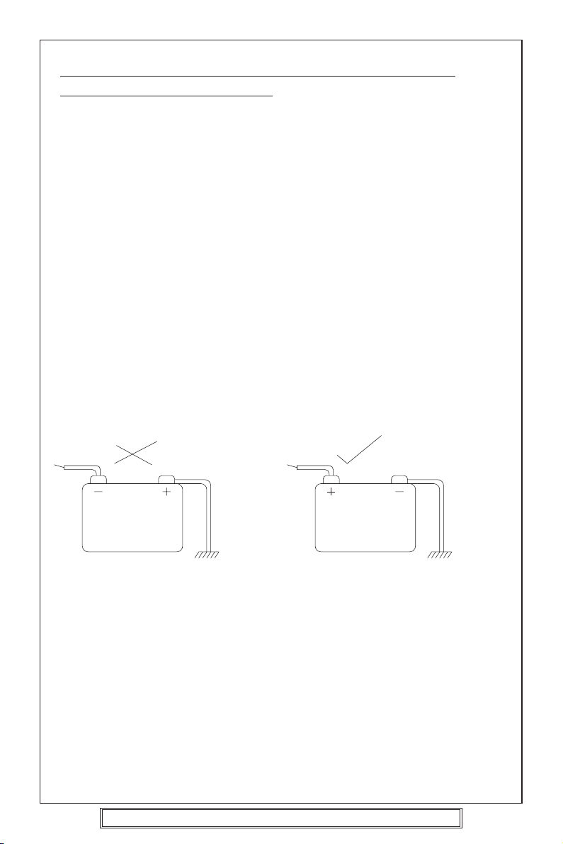
Installation/Precautions.................................................................................Page 6
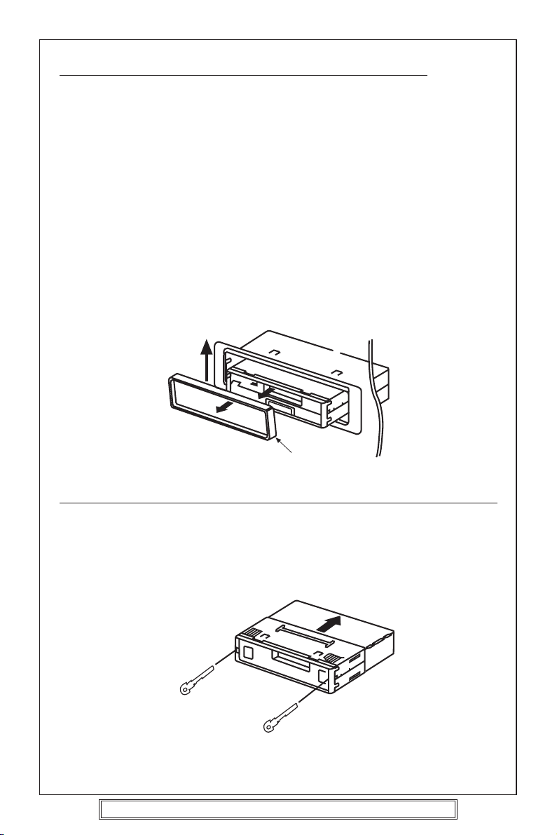
Removing and Attaching the Trim Ring ........................................................Page 7
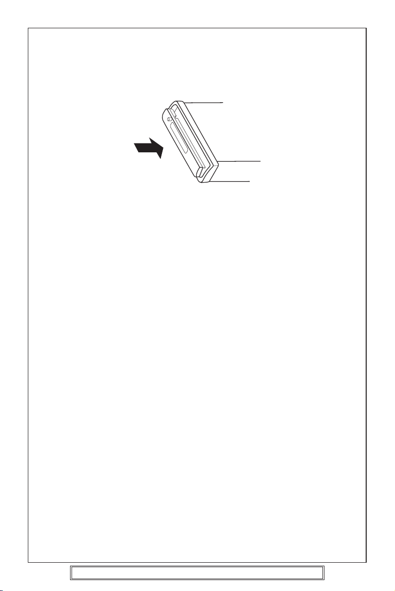
Using the Detachable Front Panel ................................................................Pages 8 - 9
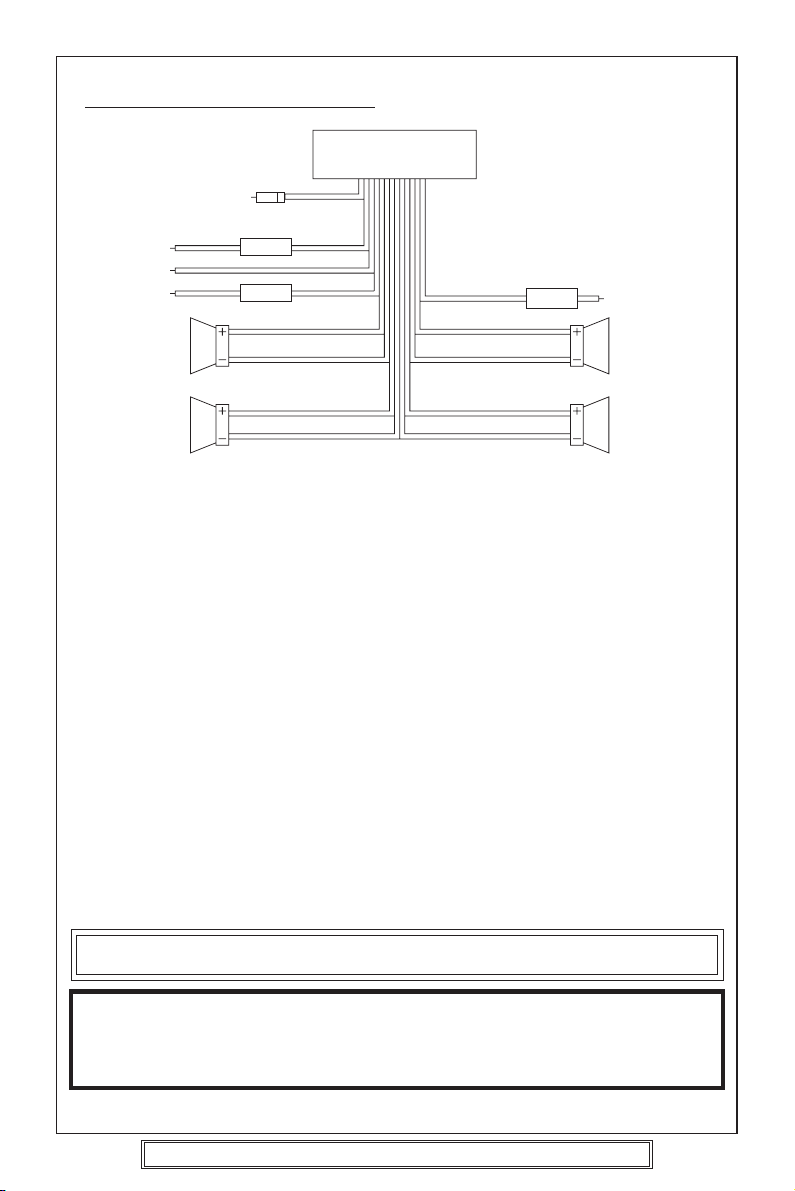
Wiring Identification ......................................................................................Page 10
ISO Plug Connections...................................................................................Pages 11 - 12
Identification of Controls and Functions.......................................................Pages 13 - 24
MP3 Operation..............................................................................................Pages 25 - 26
Remote Control Handset ..............................................................................Page 27
Aerials and Aerial Fitting ...............................................................................Page 28
Radio Reception ...........................................................................................Page 28
Radio Interference.........................................................................................Page 29
Trouble Checks and Trouble Shooting..........................................................Pages 30 - 31
Specifications................................................................................................Page 32
IMPORTANT: Do not forget to remove the transit screws on top of the unit,
before removing the fixing cage and installing the unit.
Failure to do so will result in the CD not playing.

Goodmans Product Information Helpline (02392) 391100
Installation Helpline (01132) 868613
P. 3
ACCESSORIES
Please retain the carton and packing materials, as this is the best protection for the unit
should it be necessary to return it for servicing.
(1) 1 x 15 Amp fuse (spare fuse for + 12 volt supply wire of the unit).
1 x 0.5 Amp fuse (spare for memory).
(2) 2 x ISO Plug Connector
For use when ISO plugs are not
used on your vehicle
(3) 2 x Release key
15A Fuse 0.5A Fuse
Main Unit
ISO Socket

Goodmans Product Information Helpline (02392) 391100
Installation Helpline (01132) 868613
P. 4
PLEASE READ THIS BEFORE CONNECTING THE
PLAYER TO THE VEHICLE
IMPORTANT NOTES
Prior to final installation carry out a sound check. If high distortion or intermittent sound
is experienced it is possible that the wiring to the car’s electric is poor, or that the battery
needs recharging.
If the battery and its charging circuit are OK, then rewire the red fused wire of the player
directly to the positive terminal (+) of the car battery. Car accessory shops stock the
connector blocks and the 15 Amp cable which may be necessary for extending the fuse
wire connection.
EARTHING: Make sure that the black wire on the wiring harness is connected to a good
earthing point on the car. If the chassis of the car is used as an earthing point, make sure
that the paint is scraped clean from the metal work before attaching the wire to it. It is
preferable to connect the black earthing wire directly to the negative terminal (–) of the
car battery.
WARNING: POLARITY.....
This model is only suitable for use in vehicles which have a negative earth system.
e.g.: The negative terminal of the car battery is connected to the chassis.
Connecting The Speakers And Power Cables
Before you wire your system, disconnect your vehicle battery’s positive (+) cable.
This helps prevent damage in case of a short. When you complete the wiring, reconnect
the battery cable and test your car stereo.
Note: Check with your vehicles handbook or dealer before disconnecting the vehicle
battery in case the alarm or other electronics in your vehicle requires special attention.
When connecting your car stereo’s black ground wire, be sure to connect the wire to a
metal part of your vehicle or preferably to the negative (–) terminal of the car battery.
12V
BATTERY POSITIVE
CHASSIS
12V
BATTERY NEGATIVE
CHASSIS

Goodmans Product Information Helpline (02392) 391100
Installation Helpline (01132) 868613
P. 5
PRECAUTIONS AND MAINTENANCE
•This unit is designed for negative ground 12V DC operation only. The equipment can
be used safely, if the negative terminal of the battery is connected to the vehicle metal
work.
•Do not use speakers of impedance less than 4 ohms; and do not allow the speaker
wires to be shorted together when the unit is switched on.
Otherwise it may overload or burn out the power amplifier stage.
•If the car interior is extremely hot, as after being parked in the sun, do not use the
player until the car has been driven for a while to cool off the interior.
IMPORTANT
After installing the unit, switch on the power to the unit and press this RESET button
using a pen or thin match stick.
RESET
Caution Vauxhall owners:
Vauxhall do not follow normal ISO wiring convention which will cause Goodmans radios’
to lose the radio preset memories each time the ignition switch is turned off. To prevent
such occurrences swap over the Red ignition and Orange Memory wires in the bullet
connectors attached to the wiring harness of the car radio.

Goodmans Product Information Helpline (02392) 391100
Installation Helpline (01132) 868613
P. 6
INSTALLATION/PRECAUTIONS
•Choose the mounting location carefully so that the unit will not interfere with the normal
driving functions of the vehicle.
•Avoid installing the unit where it would be subject to high temperatures, such as from
direct sunlight or hot air from the heater, or where it would be subject to dust, dirt or
excessive vibration.
•Use only the supplied mounting hardware for a safe and secure installation.
•Be sure to remove the front panel before installing the unit.
Mounting angle adjustment
Adjust the mounting angle to less than 20°.
MOUNTING EXAMPLE
Installation in the dashboard
Note:
Keep the release keys in a safe place as you may need them in future to remove the unit
from the car.
Tab
Bend these claws, if necessary
12
3
182m
53m
* Remove trim ring
* Insert release keys
* Pull unit away from cage
Insert cage into car slot
Fix cage to car
slot 4Attach the: ISO connecting cables
CD changer cable
Car aerial
To the sockets location
5Insert radio into car slot
ISO
connecting
plugs
Car aerial

Goodmans Product Information Helpline (02392) 391100
Installation Helpline (01132) 868613
P. 7
REMOVING AND ATTACHING THE TRIM RING
This model can be fitted to DIN E or ISO style dashboard slots. The clip on
trim ring is prefitted to the front of the unit for this purpose.
•It will be necessary to remove the trim ring:
a. To allow the radio to be fitted to an ISO style dashboard slot.
b. To gain access to the keyhole slots for removal of the unit from the car
slot/fixing cage.
•To remove the trim ring first remove the front panel from the radio (press the
open button and remove the front panel).
•Using your fingers lift the trim ring at its top centre and pull the ring towards
you/away from the main unit.
•The trim ring can only be fitted to the main unit one way only. A removable
label with TOP printed on it is placed on the top of the ring to indicate the
correct placement of the ring. Simply position the trim ring over the front
of the main unit and push fit the trim ring on to the unit.
REMOVING THE PLAYER FROM THE DASHBOARD/FIXING BRACKET
•Remove the front panel from the main unit.
•Lift off the trim ring and remove from the main unit.
•Insert the supplied release keys into the key slots located on the left and
right sides of the unit. Ensure that the keys are fully pressed into the slots.
•Pull on both of the release keys to remove the unit from the fixing bracket/car
slot.
Lift up and then pull
away from unit.
Trim Ring
TOP
Insert keys into key holes
and pull to remove unit.

Goodmans Product Information Helpline (02392) 391100
Installation Helpline (01132) 868613
P. 8
USING THE DETACHABLE FRONT PANEL
To Detach the Front Panel
1. Press the open button (OPEN), the front panel will fold down.
2. Remove the front panel by pulling on the middle.
3. For safekeeping, store the front panel in the supplied protective case immediately
after being removed.
4. Push the front metal plate into the main body. A “click”sound should be heard.
Protective Case
Front Panel
Front Panel
Open

Goodmans Product Information Helpline (02392) 391100
Installation Helpline (01132) 868613
P. 9
To Reinstall the Front Panel
1. Push the front panel into the main body. A ‘click’sound should be heard.
2. Note that if the front panel fails to lock in position properly, the control buttons may
not function and the display may have missing segments. Push the OPEN button
and reinstall the front panel again.
Precautions when Handling
1. Do not drop the front panel.
2. Do not put pressure on the display or control buttons when detaching or reinstalling
the front panel.
3. Do not touch the contacts on the front panel or on the main unit body. It may result
in poor electrical contact.
4. If any dirt or foreign substances adhered on the contacts, they can be removed with
a clean and dry cloth.
5. Do not expose the front panel to high temperatures or direct sunlight in anywhere.
6. Keep away any volatile agents (e.g. benzene, thinner, or insecticides) from touching
the surface of the front panel.
7. Do not attempt to disassemble the front panel.

Goodmans Product Information Helpline (02392) 391100
Installation Helpline (01132) 868613
P. 10
WIRING IDENTIFICATION
REAR VIEW OF PLAYER
1) AERIAL INPUT SOCKET 8) FRONT RIGHT POSITIVE: WHITE
2) BATTERY: RED +12 VOLT IGNITION 9) FRONT RIGHT NEGATIVE: WHITE
3) GROUND: BLACK –WITH BLACK STRIPE
4) MEMORY: ORANGE 10) REAR LEFT POSITIVE: BROWN
PERMANENT +12 VOLT 11) REAR LEFT NEGATIVE: BROWN
5) AUTO AERIAL: ORANGE/WHITE WITH BLACK STRIPE
6) FRONT LEFT POSITIVE: GREY 12) REAR RIGHT POSITIVE: YELLOW
7) FRONT LEFT NEGATIVE: GREY 13) REAR RIGHT NEGATIVE: YELLOW
WITH BLACK STRIPE WITH BLACK STRIPE
RECOMMENDED MINIMUM LOUDSPEAKER POWER RATINGS
Front loudspeakers power ratings 2 x 30 Watts RMS (2 x 60 Watts Music)
Rear loudspeakers power ratings 2 x 30 Watts RMS (2 x 60 Watts Music)
TWO SPEAKER WIRING
If you intend to use only two speakers with this radio select either front or rear wiring
INSTALLATION NOTES
(APPLICABLE TO BOTH 2 AND 4 SPEAKER CONNECTION)
This radio contains two separate power amplifiers, to prevent possible damage to these
amplifiers please ensure:
1) The vehicle chassis is not used as a loudspeaker earth (–ve return).
2) Front and Rear loudspeaker connecting wires are not joined together.
3) Any wires not used when completing a two speaker installation are fully insulated.
4) The memory wire (Orange) is connected to a permanent +12V supply.
5) The power wire (Red) is connected via the ignition switch of the vehicle.
UNIT
1
3
2
45
8
9
6
7
1210
1311
Note: Before turning the unit ON for the first time after installation please ensure the
RESET button is pressed to reset the microprocessor. For location see page 13.
IMPORTANT NOTE
If after directly connecting the unit via the vehicles ISO connector plugs it does not appear
to work (fails) to power up disconnect the orange lead bullet connector and reconnect to
the twin bullet connector socket on the red wire. Try the unit again it should power up and
can be used normally. Note this phenomenon is most frequent in Volkswagen/Audi vehicles.

Goodmans Product Information Helpline (02392) 391100
Installation Helpline (01132) 868613
P. 11
ISO PLUG CONNECTIONS
Block A: This plug is used for power supply connections only.
Block B: This plug is used for connecting the loudspeakers.
•If your vehicle is not fitted with an ISO connector but just bare wire, then
simply connect the supplied ISO plug to bare wire connector A and B to the
radio’s ISO socket and connect the bare wire ends to the vehicles loudspeakers
according to the wiring codes as shown below. Make sure all connections
and any unused wires are insulated to prevent shorting.
•ISO Connector pin A6 (Car Light Illumination) is not used on this player.
ISO-PLUG A
ISO-PLUG B
A8
A4
A7
A5
B1
B2
B3
B4
B5
B6
B7
B8
CARRADIO
ISO - PLUG
Yellow
Yellow with black stripe
White
White with black stripe
Grey
Grey with black stripe
Brown
Brown with black stripe
A4
A5
A7
A8
A6
Orange
Orange/White
Red
Black
---
+12 Volt memory
+ 12 Volt Auto. Antenna
+12 Volt Power
Earth (Ground)
Car light (Illumination)
AERIAL SOCKET
ISO - Plug
1357
2468
1357
2468
B
A
ISO Function Colour
B1 Speaker right rear +
B2 Speaker right rear –
B3 Speaker right front +
B4 Speaker right front –
B5 Speaker left front +
B6 Speaker left front –
B7 Speaker left rear +
B8 Speaker left rear –
ISO Function Colour
15A
0.5A

Goodmans Product Information Helpline (02392) 391100
Installation Helpline (01132) 868613
P. 12
Recommended Minimum Loudspeaker Power Ratings
Front and Rear Loudspeakers power ratings 4 x 30 Watts RMS.
Two Speaker Wiring
If you intend to use only two speakers with this radio select either front or rear wiring in
accordance with the power handling of the speakers fitted to you vehicle, when installing
connect as per the instructions given on page 10 - 11.
Installation Notes
(Applicable to both 2 and 4 speaker connection)
This radio contains two separate power amplifiers, to prevent possible damage to these
amplifiers please ensure:
i) The vehicle chassis is not used as a loudspeaker earth (-ve) return.
ii) Front and Rear loudspeaker connection wires are not joined together.
iii) Any wires not used when completing a two speaker installation are fully insulated.
iv) The memory wire (orange) is connected to a permanent +12V supply.
v) The power wire (Red) is connected via the ignition switch of the vehicle.
If bare wires are to be used, insert the 2 x supplied
ISO plugs into the ISO socket of the car radio.
The plugs are handed and will only fit one way.
Connect the bare wires ends in accordance with the instructions given on page 10.

FUNCTION KEYS
1. PTY Button
2. TA Button
3. AF Button
4. Eject Button
5. Disc Slot
6. Mode Button
7. Open Button
8. Audio Adjust Knob
9. Remote Sensor IR
10. Select Button
11. Equalization Button
12. Flashing LED
13. Band/Loudness Button
14. Preset Buttons
15. Display Button
16. Manu/Skip Button ( )
17. Manu/Skip Button ( )
18.
Auto Memory Store/Program Scan Button
19. Disc Pause Button
20. Disc Scan Button
21. Disc Repeat Button
22. Disc Shuffle Button
23. Vacuum Fluorescent Display
24. Reset
Goodmans Product Information Helpline (02392) 391100
Installation Helpline (01132) 868613
P. 13
IDENTIFICATION OF CONTROLS AND FUNCTIONS
5 12 4 24
1419
23 16 3
11513
2
11106
87 17
2220 21 18
9

Goodmans Product Information Helpline (02392) 391100
Installation Helpline (01132) 868613
P. 14
CONTROLS
1. Power/Illumination button (POWER/ILL) (8)
Press to turn power to the player ON or OFF.
Note: To power off press and hold for several seconds.
Press the Volume Knob repeatedly to adjust the display brightness.
2. Audio Adjust Knob (8) / Select button (SEL) (10)
The Volume, Bass, Treble, Balance and Fader functions are electronic and are selected
for adjustment by this button. The function defaults to the volume setting which can
be increased/decreased by rotating the Audio Adjust Knob (8).
To adjust the Bass, Treble, Balance or Fader functions press the SEL button (10)
repeatedly unit the desired function shows in the display. Rotate the Audio Adjust
Knob (8) to adjust the desired function. The display will show the amount by which
the function has been altered.
If no adjustments have been made within 4 seconds of pressing the SEL button (10),
the player will assume the correct setting has been made and will automatically return
to normal/Volume setting.
VOLUME SELECT BASS SELECT TREBLE SELECT BALANCE SELECT FADER SELECT
151311106
8
12 24
9

3. How to set loud ON/OFF (13)
Press and hold, (BND, LOU) (13) button for more than 2 seconds, until the Display
shows “LOUD ON”. Repeat again to turn LOUD off.
4. Display
Press DISP button (15) to operate as the conversion of each display mode as follows:
- In case of receiving a RDS station
In radio mode: ->PS ->CT ->FREQ. ->PTY ->
In CD (MP3) mode: ->CD (MP3) ->CT ->PS ->FREQ. ->PTY ->
- In case of no receiving CT or PTY information, the display shows as “NO CLOCK”
or “NO PTY”.
- In case of receiving a non RDS station
In radio mode: ->“NO CLOCK”->FREQ. ->“NO PTY”->
In CD (MP3) mode: ->CD (MP3) ->CT ->FREQ. -> “NO PTY”->
Each displaying time is several seconds, and come back to 1’st
position after several seconds.
Notes:
- CT = clock time
- FREQ. = frequency
5. Equalization
Press P-EQ button (11) to turn on equalization function and to select desired audio
mode. There are five kinds of mode as below:
FLAT CLASSICS POP M ROCK M DSP OFF
6. Select Mode
Press MODE button (6) shortly to choose desired listening mode.
[e.g. radio mode to CD (MP3) mode]
The unit can be connected a portable audio player throught the AUX jack (back of the
unit).
7. Flashing Led
This LED (12) will flash when the front panel is removed.
8. Remote Sensor
Point the remote control handset to the remote sensor IR (9). Press the function keys
on the handset to control the system.
9. Reset
RESET button (24) must be activated with either a ball point pen or thin metal object.
RESET button (24) is to be activated for the following reasons:
- Initial installation of the unit when all wiring is completed.
- All the function buttons do not operate.
- Error symbol on the display.
Note: If press RESET button (24), the unit can’t work yet, please use a cotton swab
soaked in isopropyl alcohol to clean the socket on the back of the front panel.
Goodmans Product Information Helpline (02392) 391100
Installation Helpline (01132) 868613
P. 15

Goodmans Product Information Helpline (02392) 391100
Installation Helpline (01132) 868613
P. 16
1. Press the POWER/ILL button (8) to turn on the unit.
2. Press BND/LOU (FM/MW/LW) (13) to select the desired band, FM1, FM2, FM3, MW
or LW.
3. Press MANU/SKIP ( ) (16) or MANU/SKIP ( ) (17).
The unit will automatically seek a station upwards or downwards and stop when a
station is tuned in.
When there are many stations the automatic tuning stops frequently.
MANUAL TUNING
1. Press the POWER/ILL button (8) to turn on the unit.
2. Press BND/LOU (13) to select the desired band, FM1, FM2, FM3, MW or LW.
3. Use MANU/SKIP ( ) (16) or MANU/SKIP ( ) (17) for more than 2 seconds then
“Manual”. Will show in this display. Press MANU/SKIP ( ) (16) or MANU/SKIP
( ) (17) to tune to your desired station.
Radio reception
AUTOMATIC TUNING (SEEK)
16
13
8 17

Goodmans Product Information Helpline (02392) 391100
Installation Helpline (01132) 868613
P. 17
Auto Music Store (AMS Function)
•Select FM1, FM2, FM3, MW or LW band.
•
Press and hold the AMS button (18) for more than 2 seconds (Auto Preset Store).
•The 6 strongest available station will be automatically saved in the memory on preset
button 1 - 6 (14).
Notes:
a. The complete band will be scanned and as each strongest station is received it will
automatically be placed in the preset 1-6 memory locations.
b. Any stations that were entered into the AMS memory before the AMS operation
commenced will be erased or repositioned after AMS operation has been completed.
c. If the radio has been set for TA mode (TA is shown in the display) the AMS will only
search for the first 6 stations that are broadcasting TA/TP/RDS data. Press the TA
buttons (2) until TA is no longer shown in the display it this is not desired.
d. When there are less than 6 different stations in your area then the AMS will not
memorize any stations into the remaining preset memory locations.
e. AMS will not operate on LW band.
Manual Preset Memory
1. Press BND/LOU button (13) to select band required FM1, FM2, FM3, MW or LW.
2. Tune to the desired radio station by pressing SKIP UP/DOWN button (16)/(17).
3. Press and hold the desired preset memory button (14) 1-6 until a beep is heard.
The station has now been entered/memorized into the selected preset position.
4. To recall the AMS or normal/manually memorized stations, briefly press the AMS (18)
or BND/LOU button (13) and then press the desired preset 1-6 button (14).
To Hear a Preset Station
Select desired band and press the appropriate preset button (14) 1-6 into which you have
previously stored the station.
MEMORY PRESET TUNING
14 13
2
18
1617

Goodmans Product Information Helpline (02392) 391100
Installation Helpline (01132) 868613
P. 18
The following functions are available with this unit using the RDS data system.
Station Name Display
Displays the station name in the display window.
Automatic Re-tuning-AF function
Re-tunes to a stronger signal station in the same broadcasting network automatically
using the PI and AF data.
The illustration below shows an example: four stations of the same broadcasting network
and a driver passes through from the point A to B.
The reception frequency of the station in the network changes from 98.5 MHz to 102.5
MHz as the driver passes through each transmitter.
By using the AF function, the driver can keep listening to the programme in the same
broadcasting network without retuning operation while driving from the point A to B.
Traffic information Reception - TA function
Searches and stands by for a traffic information station using the TP and TA data.
By this function, the unit automatically monitors the station and changes its mode to the
traffic information reception when the broadcast starts even whilst listening to CD.
RDS reception
OVERVIEW OF THE RDS FUNCTION
BBC RI
98.5 MHz
107.6 MHz
96.0 MHz 102.5 MHz
Station Station
Point A
Point B

Goodmans Product Information Helpline (02392) 391100
Installation Helpline (01132) 868613
P. 19
Note: Station name will only show when using FM band.
1. Tune in a desired FM station using the automatic or manual tuning methods.
If the received station is transmitting RDS data. In a few seconds, station name will
be displayed.
Notes
•RDS data can be received only on the FM band. It cannot be received on the
MW/LW band.
•The RDS functions of this unit cannot be used if the received FM station is not
transmitting the RDS data and may not work properly in area without RDS
transmission.
To change the display to frequency or programme type name
Press DSP (Display) (15)
Press on DSP (15) changes the display as follows:
Station name display Clock Frequency display Program type display
If the RDS station is not transmitting the PTY (program type) or CT (Clock) data,
programme type or clock will not show in the display.
STATION NAME DISPLAY
FI 104.30 BBC RI
15

Goodmans Product Information Helpline (02392) 391100
Installation Helpline (01132) 868613
P. 20
AF function
AUTOMATIC RE-TUNING
Note: Auto Re-tuning will only operate on FM band.
1. Tune to a desired RDS station using the automatic or manual tuning methods.
2. AF function is switched ON/OFF by pressing the AF button (3).
When RDS is displayed. AF function is switched on. If no AF data is received, the AF symbol blinks.
How the AF function works?
In AF mode, the radio measures at regular intervals the signal strength at frequencies
that are mentioned in the list of Alternative Frequencies (AF’s) of the current station.
If an alternative frequency is found, it switches immediately to the new frequency if the
quality of the current station becomes suddenly very poor, or if its RDS data cannot be
received. The quality of a station is a function of signal level as well as multipath condition.
Note: In areas of severe multipath reception this may cause noise or the AF function to constantly
change. Should this occur then switch off the AF function. Try using the AF function later.
Regional
Press AF button (3) longer than 2 seconds (until the radio beeps.)
Displays shows REGIONAL Mode status and allows switching the REGIONAL Mode
ON/OFF. The current state of the REGIONAL Mode is indicated by a message “REG
ON”or “REG OFF”. Which is displayed for 4 seconds after the AF button (3) is pressed.
To check whether an Alternative Frequency is a real Alternative for the current station,
the radio compares PI codes. (Programme Identity)
Regional Mode is ON: The PI codes must be exactly identical.
Regional Mode is OFF: The Region identification code in the PI code is ignored.
When regional mode is OFF, the radio may switch from a National Programme to a local
variant of that Programme, or from a local station in one area to a local station of an
other area. When Regional Mode is ON, the radio will only switch to an alternative
station that broadcasts exactly the same programme. For best performance it is
recommended that the Regional function remains in the OFF, Function is REG OFF.
CT FUNCTION (CLOCK TIME)
This software incorporates a real time clock which is updated from the RDS signal.
When a station is tuned in the unit will decode the incoming clock data and after 2
minutes will display the correct time when the DSP button is pressed.
Press DSP- Clock is displayed; Press DSP twice - Programme type is displayed; Press
DSP 3 times - Frequency is displayed.
After 5 seconds the display will revert to station name display.
Note: Some stations do not transmit a PTY or CT information and therefore the clock
display may not be available.
3
Table of contents
Other Goodmans Car Stereo System manuals
Popular Car Stereo System manuals by other brands

Metra Electronics
Metra Electronics 99-7520B installation instructions

Magnadyne
Magnadyne M2500CD Operation and installation manual

Ground Zero
Ground Zero NUCLEAR Series owner's manual

Pioneer
Pioneer AXM-P90RS Operation manual

Adcom
Adcom GFI-4400 owner's manual

Lightning Audio
Lightning Audio LC05 Installation and application manual