Goodwe GW2500-BP User manual

BP SERIES USER MANUAL
35 0-0 01 11 -01
HYBRID CONVERTER
Android market
iOS App Store
GoodWe(China)
No.189 Kunlunshan Rd., SND,
Suzhou, 215163, China
T: +86 512 6239 6791(service)
GoodWe(Australia)
19 Fairleigh Street, Glenroy,
VIC, 3046, Australia
T: +61 3 9324 0559(service)
GoodWe(UK)
46 Foyle Road
N17 0NL United kingdom
T:+44 (0)333 358 3184
service co.uk
London
@goodwe.
GoodWe(Netherlands)
Zevenwouden 194 ,
3524 CX Utrecht, the Netherlands
T: +31 6 1988 6498(service)
Note: The information above is subject to change without prior notice, details refer to www.goodwe.com.cn.
Global Service Hotline:400-998-1212

........................................................................................... 01
1. Introduction
............................................ 02
.................................. 03
.............. 03
............................. 04
3.1 Packing List
3.2 Product Overview
3.3 Selecting The Mounting Location
3.4 Mounting Procedure
3. Installation
........................................................................................... 22
7. Work Modes
.................................................................................. 24
8. Troubleshooting
2. Safety and Warning
. ........................ 01.....................
................................................ 02
2.1 Symbols
2.2 Safety
5. Electrical Connection ..... 09
................................ 10
....................... 13
.................... 14
....................... 15
.................................... 15
5.1 PV INPUT and TO INVERTER Connection
5.2 Battery Connection
5.3 EzMeter & CT Connection
5.4
5.5
5.6 USB Connection
5.7
Communication Connection
EzManage App Illustration
EzConverter & Li-ion Battery
Connection (optional) ........................... 16
6. System Operation ..................................... 19
........ 19
.... 23
6.1 Indicator Lights
6.2 User Interface And Use Of The Display
6.3 Setting the Range Of Battery Parameters
9. Technical Parameters................................................................... 29
4. System Connection Diagram ............................................. 05
9. Certificates
................................................................................................... 30

Before installation, please check the unit. Be sure that nothing inside the package is damaged. You should have received the
following items inside the package:
2 Safety and Warning
01 02
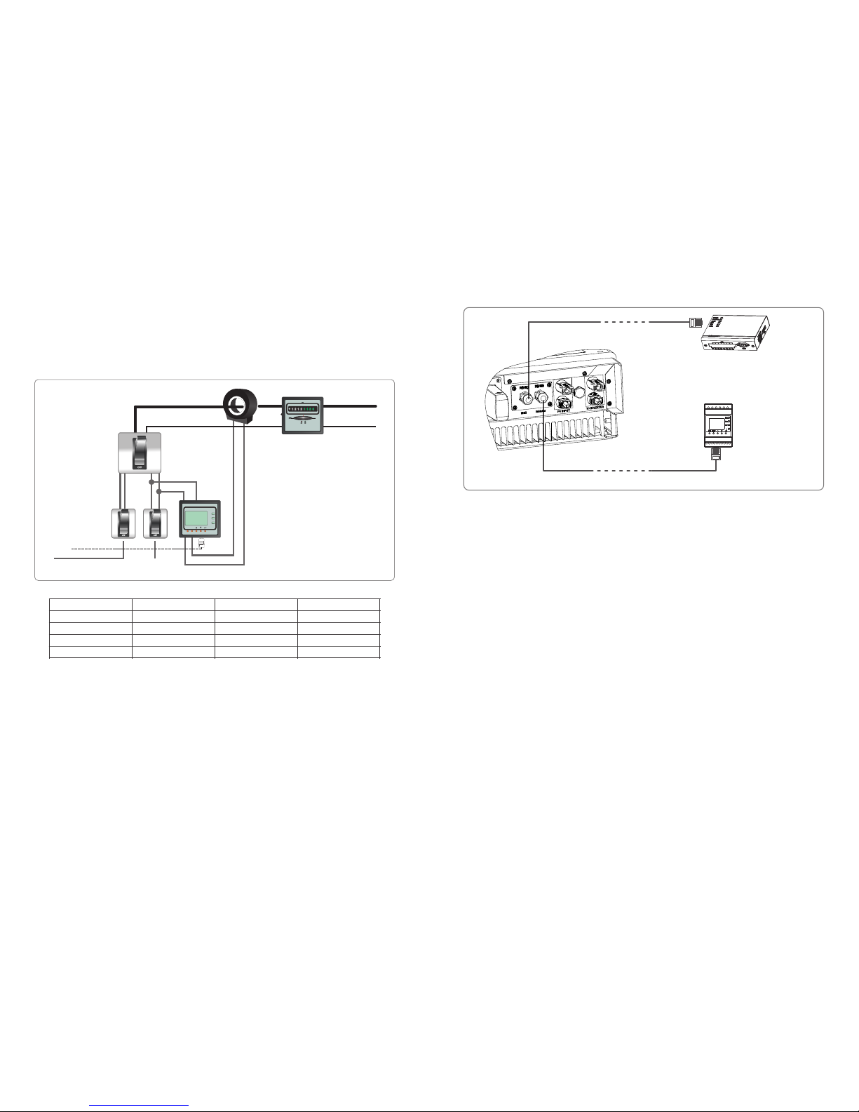
A GoodWe BP series hybrid converter can upgrade a generic single phase PV grid-tied inverter into an energy-storage system.
During daytime, PV panels generate electricity which can be firstly supplied to the local loads, then the excess energy will be used to
charge the batteries via the hybrid converter. During the night, the battery will discharge. The electricity will be provided to the local
loads with the hybrid converter and the PV grid-tied inverter. The hybrid system improves the self-consumption ratio greatly.
● Installation, maintenance and connection of hybrid converter must be performed by qualified personnel, in compliance with local
electrical standards, wiring rules and the requirements of local power authorities and/or companies
● To avoid electric shock, PV input, PV output, battery connection of the hybrid converter must be terminated at least 5 minutes
before performing any installation or maintenance.
● The temperature of some parts of the hybrid converter may exceed 60 during operation. To avoid being burnt, do not touch it
during operation. Let it cool before touching it.
● Keep children away from the hybrid converter.
● Static electricity may damage electronic components. Appropriate method must be adopted to prevent such damage to the
equipment; otherwise the hybrid converter may be damaged and the warranty annulled.
● When exposed to sunlight, the PV array generates dangerous high DC voltage. Please operate according to our instructions, or it
will result in danger to life.
● Ensure the output voltage of the proposed PV array is lower than the maximum rated input voltage of the hybrid converter;
otherwise the equipment may be damaged and the warranty annulled.
● Do not open the front cover of the hybrid converter without permission. Apart from performing work at the wiring terminal (as
instructed in this manual), touching or changing components without authorization may cause injury to people, damage to
equipment and annulment of the warranty.
● Completely isolate the equipment should :disconnect the PV input, output terminal, disconnect the battery terminal or breaker.
● Prohibit inserting or pulling the PV and battery terminals when the hybrid converter is working.
● PV modules should have an IEC61730 class A rating.
● If the equipment is used in a manner not specified by the manufacturer, the protection provided by the equipment may be
impaired.
Caution!
Failure to observe a warning indicated in
this manual may result in injury.
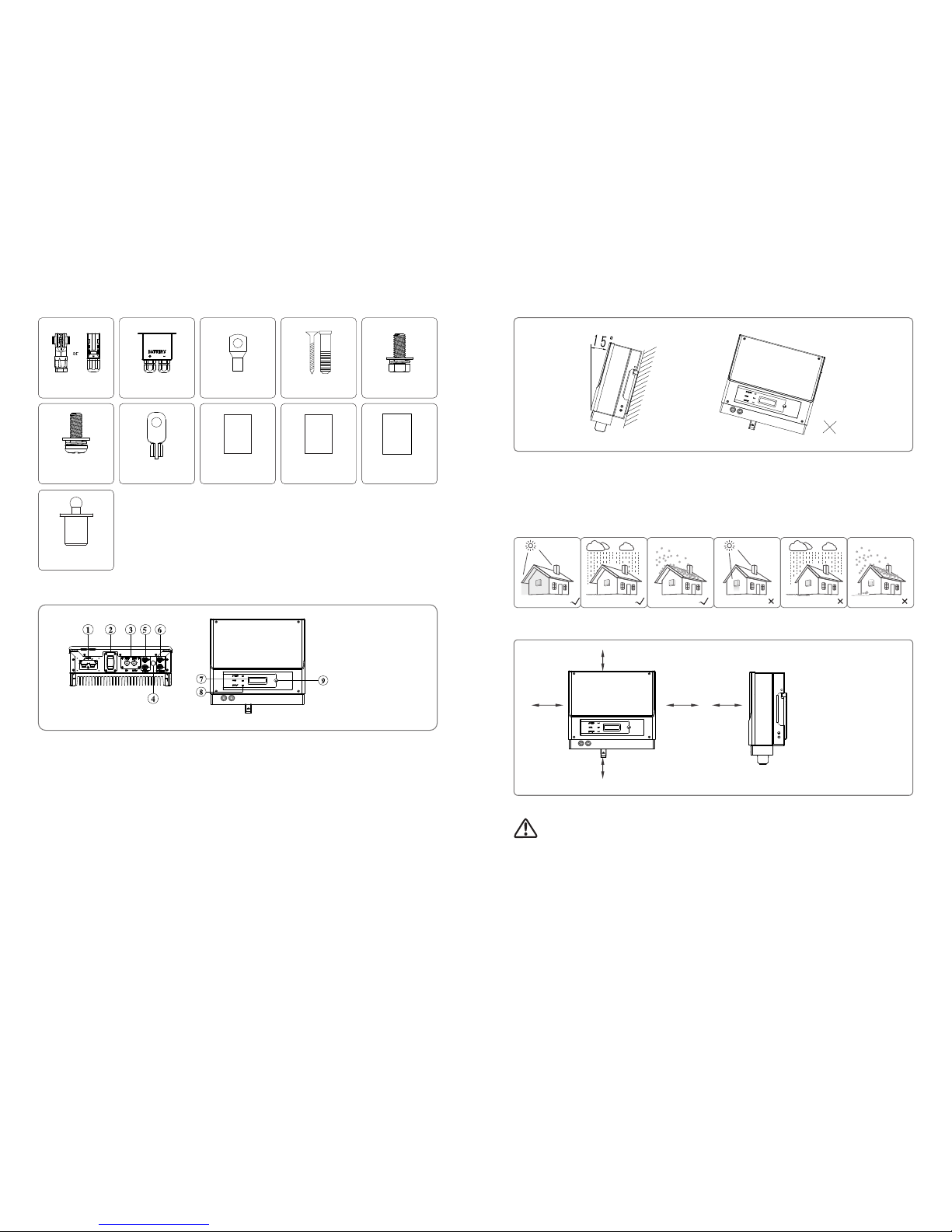
Wall-mounted
Bracket×1
BP machine×1Positive DC Plug×2
EzMeter&CT × 1
EzConverter
(optional) × 1
Danger of high voltage and electric shock!
No more than six (6) identical packages may
be stacked on each other.
Danger of hot surface!
This side up; the package must always be
transported, handled and stored in such a way
that the arrows always point upwards.
Product should not be disposed as
household waste.
The package/product should be handled
carefully and never be tipped over or slung.
Keep dry; the package/product must be
protected from excessive humidity and must be
stored under cover.
Signals danger due to electrical shock and indicates the time (5 minutes) to allow after the
inverter has been turned off and disconnected to ensure safety in any installation operation.
2.1 Symbols
2.2 Safety
3 Installation
3.1 Packing List
● Before using the hybrid converter, please read all instructions and cautionary markings on the unit and this manual. Store the
manual where it can be accessed easily.
●The BP series hybrid converter of Jiangsu GoodWe Power Supply Technology Co. Ltd. (hereinafter referred to as GoodWe) strictly
conforms to related safety rules in design and testing.
●Safety regulations relevant to the location shall be followed during installation, operation and maintenance.
●Improper operation may have a risk of electric shock or damage to equipment and property.
1 Introduction
Components of the product can be recycled.
CE mark
Figure 1-1 Basic system overview

03 04
3.2 Product Overview
Mounting location should be selected based on the following aspects:
●
● Mount on a solid surface.
● Select a well ventilated place sheltered from direct sun radiation.
● Install vertically or tilted backwards by max 15°. The device cannot be installed with a sideways tilt. The connection area must
point downwards. Refer to Figure 3.3-1.
The installation method and mounting location must be suitable for the Hybrid converter's weight and dimensions.
3.3 Selecting The Mounting Location
● In consideration of heat dissipation and convenient dismantlement, the minimum clearances around the machine should be no
less than the following values:
Upward-----------------300mm
Downward--------------500mm
Front----------------------300mm
Left & right------------------200mm
Figure 3.3-2
300mm
500mm
200mm 200mm 300mm
● In order to achieve optimal performance, the ambient temperature should be lower than 45 °C.
● For the convenience of checking the LCD and possible maintenance activities, please install the machine at eye level.
● The Hybrid converter should NOT be installed near inflammable and explosive items. Any strong electro-magnetic equipment
should be kept away from installation site.
● Product label and warning symbol should be clear to read after installation.
● Please avoid direct sunlight, rain exposure, snow lay up when installing.
(1) Use the wall-mounted bracket as a template and drill 5 holes in the wall, 10 mm in diameter and 80 mm deep. Referred to Figure
3.4-1
(2) Fix the wall mounting bracket on the wall using the expansion bolts in the accessories bag.
(3) Hold the hybrid converter by the side groove as Figure 3.4-2.
(4) Install the hybrid converter on the wall-mounted bracket. Referred to Figure 3.4-3, 3.4-4.
No direct sunlight
3.4 Mounting Procedure
No rain exposure No snow lay up Direct sunlight Rain exposure Snow lay up
Pan head screw × 5 User Manual×1
User
Manual
PE terminal ×1
Instruction
of
Fast
Installation
Negative DC Plug×2 Battery cover × 1 Battery terminal × 2 Expansion Bolts×5Hexagon head
screw × 2
Fast Installation
Guide×1
Wi-Fi Connection
Guide×1
Wi-Fi
Connection
Guide
1.Battery input
2.External Wi-Fi module
3.Communication port
4.
5.PV input terminals
6.TO INVERTER terminals
7.LCD display
8. lights
9.Button
Air vent
Indicator
Figure 3.2-1
Figure 3.3-1
Waterproof terminal ×1

05 06
2) Single MPPT PV grid-tied inverter, with two DC inputs
Connection criteria:
Strings must be equal.
DC output of the GW2500-BP must be connected to one input of the PV grid-tied inverter.
Open voltage and short current of panels when connected in parallel must not exceed max voltage and current of inverter.
●
●
●
Note: if equipped with lead-acid battery, do not need to connect④⑤.
Figure 3.4-3 Figure 3.4-4
a
b
Detail a
Detail b
4. System Connection Diagram
Figure 3.4-1
250mm
125mm
130mm
260mm
Figure 3.4-2
Below configurations are suitable for BP series hybrid converter
1) Single MPPT PV grid-tied inverter, with one DC input
To EzConverter
EzConverter
④
GW2500-BP
Single-MPPT
One DC input
Grid-tied inverter
Grid
RS-485
Meter
BATTERY
Load
Distribution box
CT
①②
③
⑤
Main
breaker
EzMeter
Sub
breaker RUN
COM
P_R
FN SET
⑦
EzManage
To EzMeter
⑥
⑧
① PV INPUT connection
② TO INVERTER connection
③ Battery connection
⑤
⑥ To EzMeter communication cable
EzConverter & Li-ion battery connection
④ To Ezconverter communication cable
⑦ Ezmanage Illustration
⑧ EzMeter & CT connection
Figure 4.1
Power cable
Communication cable
POWER
RUN
FAULT
To EzConverter
EzConverter
④
GW2500-BP
Single-MPPT
Two DC input
Grid-tied inverter
Grid
RS-485
Meter
BATTERY
Load
Distribution box
CT
①②
③
⑤
Main
breaker
EzMeter
Sub
breaker RUN
COM
P_R
FN SET
⑦
EzManage
① PV INPUT connection
② TO INVERTER connection
③ Battery connection
⑤
⑥ To EzMeter communication cable
EzConverter & Li-ion battery connection
To EzMeter
⑥
⑧
④ To Ezconverter communication cable
⑦ Ezmanage Illustration
⑧ EzMeter & CT connection
Figure 4.2
Power cable
Communication cable
POWER
RUN
FAULT
Table of contents
Popular Media Converter manuals by other brands

H&B
H&B TX-100 Installation and instruction manual

Bolin Technology
Bolin Technology D Series user manual

IFM Electronic
IFM Electronic Efector 400 RN30 Series Device manual

GRASS VALLEY
GRASS VALLEY KUDOSPRO ULC2000 user manual

Linear Technology
Linear Technology DC1523A Demo Manual

Lika
Lika ROTAPULS I28 Series quick start guide

Weidmuller
Weidmuller IE-MC-VL Series Hardware installation guide

Optical Systems Design
Optical Systems Design OSD2139 Series Operator's manual

Tema Telecomunicazioni
Tema Telecomunicazioni AD615/S product manual

KTI Networks
KTI Networks KGC-352 Series installation guide

Gira
Gira 0588 Series operating instructions

Lika
Lika SFA-5000-FD user guide