Gopel Electronic USB 4112 User manual

GOEPEL electronic GmbH
Goeschwitzer Str. 58/60 •D-07745 Jena
+ 49-3641-6896-597 • ats_support@goepel.com • www.goepel.com
USB/ basicCON 4112
4:1 LVDS Multiplexer
User Manual
(Translation of Original docu)
Document version 1.1

Issue: November 2014
© 2014 GOEPEL electronic GmbH. All rights reserved.
The software described in this manual as well as the manual itself are supplied under license
and may be used or copied only in accordance with the terms of the license.
The customer may make one copy of the software for safety purposes.
The contents of the manual is subject to change without prior notice and is supplied for information
only.
The hardware and software might be modified also without prior notice due to technical
progress.
In case of inaccuracies or errors appearing in this manual, GOEPEL electronic GmbH assumes
no liability or responsibility.
Without the prior written permission of GOEPEL electronic GmbH, no part of this documentation
may be transmitted, reproduced or stored in a retrieval system in any form or by any means
as well as translated into other languages (except as permitted by the license).
GOEPEL electronic GmbH is neither liable for direct damages nor consequential damages from
the company’s product applications.
Printed: 27.11.2014
All product and company names appearing in this manual are trade names or registered trade names of their respective owners.

Table of Contents
USB 4112/ basicCON 4112 – User Manual I
1INSTALLATION..............................................................1-1
1.1 HARDWARE INSTALLATION ...................................................1-1
1.2 DRIVER INSTALLATION........................................................1-2
2HARDWARE ...................................................................2-1
2.1 DEFINITION .....................................................................2-1
2.2 TECHNICAL DATA ..............................................................2-3
2.2.1
Dimensions
............................................................2-3
2.2.2
Properties
..............................................................2-3
2.3 CONSTRUCTION AND FUNCTION.............................................2-4
2.3.1
General
..................................................................2-4
2.3.2
Hardware Initialization
............................................2-4
2.3.3
Addressing
.............................................................2-5
2.3.4
Power Supply
.........................................................2-5
2.3.5
Connector Pinout
....................................................2-5
2.4 ACCESSORIES...................................................................2-6
3G-API PROGRAMMING ..................................................3-1


Installation
USB 4112/ basicCON 4112 – User Manual 1-1
1Installation
1.1 Hardware Installation
We recommend to install the device driver software before
connecting the device to the PC/ Laptop (see Driver Installation).
The USB 4112 board can only be operated when it is installed in one
of the GOEPEL electronics USB Racks USB 1004, USB 1008 or USB 1016.
USB 4112:
Please make absolutely certain that all of the hardware installation
procedures described below are carried out with your system
switched off.
Select an empty slot of your USB Rack. First remove the slot sheet
covering the slot (if mounted). To do that, loose the two screws.
Insert the board carefully via the guides into the prepared slot.
Push it finally into the slot till to the arrester by applying a little
pressure.
Then, tighten the two outer screws at the front panel to fix the board.
When installing the board, touch it at its edges only.
Never touch the surface of the board, because otherwise it may be
destroyed by electrostatic discharge.
To remove the board from the USB Rack (if necessary), unscrew the
two outer screws. By the lever at the front panel the board can be
dissolved from the slot and then be unplugged.
basicCON 4112 can be directly connected to the PC or Laptop.
basicCON 4112:
Connect the USB female at the device’s rear side to the PC/ laptop
using the supplied USB cable.
If necessary, see chapter Power Supply, connect the supplied power
supply unit or an own voltage source to the corresponding ext. Power
Supply connections at the device’s rear side.
Please refer to chapter Addressing regarding the addressing of
several USB 4112 boards.
Please refer to chapter Connector Pinout regarding the connections
at the device’s front side.

Installation
1-2 USB 4112/ basicCON 4112 – User Manual
1.2 Driver Installation
Windows Device Driver
For proper installation of the GOEPEL electronics USB drivers on your
system, we recommend to execute the GUSB driver setup.
To do that, start the
GUSB-Setup-*.exe
setup program
(of the supplied CD, to be find under
USB4112-basicCON4112
\
Driver
,
the asterisk “*” stands for the version number) and follow the
instructions.
At present, the available device driver supports Windows®XP
as well as Windows®7/ 32 Bit and Windows®7/ 64 Bit systems.
The USB interface uses the high-speed data rate according to the
USB2.0 specification (if possible, otherwise full-speed).
Due to the plug-and-play ability of Windows®, the device will be
automatically recognized by the operating system.
On completion of the installation process, Windows®will request you
to reboot your computer.
For safe and reliable operation this step is strongly recommended.
After driver installation/ hardware installation, you can check by the
Device Manager whether the devices are properly embedded by the
system.
The following figure shows the successful embedding of a USB 4112
board or basicCON 4112 device:
Please note that the Device Manager shows all USB controllers.
Figure 1-1:
Device Manager Display

Hardware
USB 4112/ basicCON 4112 – User Manual 2-1
2Hardware
2.1 Definition
The USB 4112LVDS Multiplexer board with USB 2.0 Interface of
GOEPEL electronic GmbH is used to distribute LVDS signals (ANSI
TIA/EIA-644).
The board is a 4 to 1 multiplexer for LVDS signals with a bandwidth up
to 3.125 GBit/s at maximum.
Additionally, the board is used as signal repeater.
USB 4112 boards can only be operated in one of the
GOEPEL electronics USB Racks USB 1004, USB 1008 or USB 1016
covering up to 16 GOEPEL electronics USB boards.
Power supply comes from the USB Rack.
Figure 2-1:
USB 4112

Hardware
2-2 USB 4112/ basicCON 4112 – User Manual
basicCON 4112 is a GOEPEL electronic GmbH stand-alone device based
on a USB 4112board to be connected directly to a PC or Laptop. It has
been developed for the independent operation out of complex test
systems.
basicCON 4112 can be supplied via the USB interface or via the ext.
Power Supply connections (see Power Supply).
At the device’s rear side, there are the following connections:
♦USB-B female for the USB 2.0 interface
with USB standard assignment
♦DC female for the AC adaptor plug (part of delivery)
♦Banana females for power supply
Please use for external power supply either the banana females
OR the DC female for the AC adaptor plug.
Additionally, please refer also to the corresponding chapter
regarding Power Supply.
Figure 2-2:
basicCON 4112
Figure 2-3:
basicCON 4112 – rear side

Hardware
USB 4112/ basicCON 4112 – User Manual 2-3
2.2 Technical Data
(W x H x D):
♦USB 4112: 4 HP x 100 mm x 160 mm
♦basicCON 4112: 130 mm x 55 mm x 200 mm
The dimensions given for USB 4112 (without front panel and
connectors) correspond to standard dimensions in a
GOEPEL electronics USB-Rack.
The USB 4112 board has the following characteristics:
Symbol Characteristic Value Min. Typ. Max. Unit Remarks
Power Supply
USS Supply voltage 5 V Supply via USB possible
(basicCON 4112)
ISS Supply current 200 400 mA
USExt External Power supply 7 12 25 V IMax = 170mA at 12V
Optionally for basicCON 4112
LVDS
UID Differential LVDS input voltage 1 V
IID Differential input current ±1 ±10 µA
RIN Input resistance 100 Ω
CIN Input capacity 1.7 pF
UOD Differential LVDS output voltage 250 350 450 mV
IOS Output short-circuit current ±55 mA
ROUT Output resistance 100 Ω
COUT Output capacity 1.2 pF
Control channel
UCTRL Voltage of the Control channel 40 V
ICTRL Current of the Control channel 250 mA
Please use the supplied USB cable to connect the devices to the
PC’s/ laptop’s USB interface.
Other cables may be inapplicable.
2.2.1 Dimensions
2.2.2
Properties

Hardware
2-4 USB 4112/ basicCON 4112 – User Manual
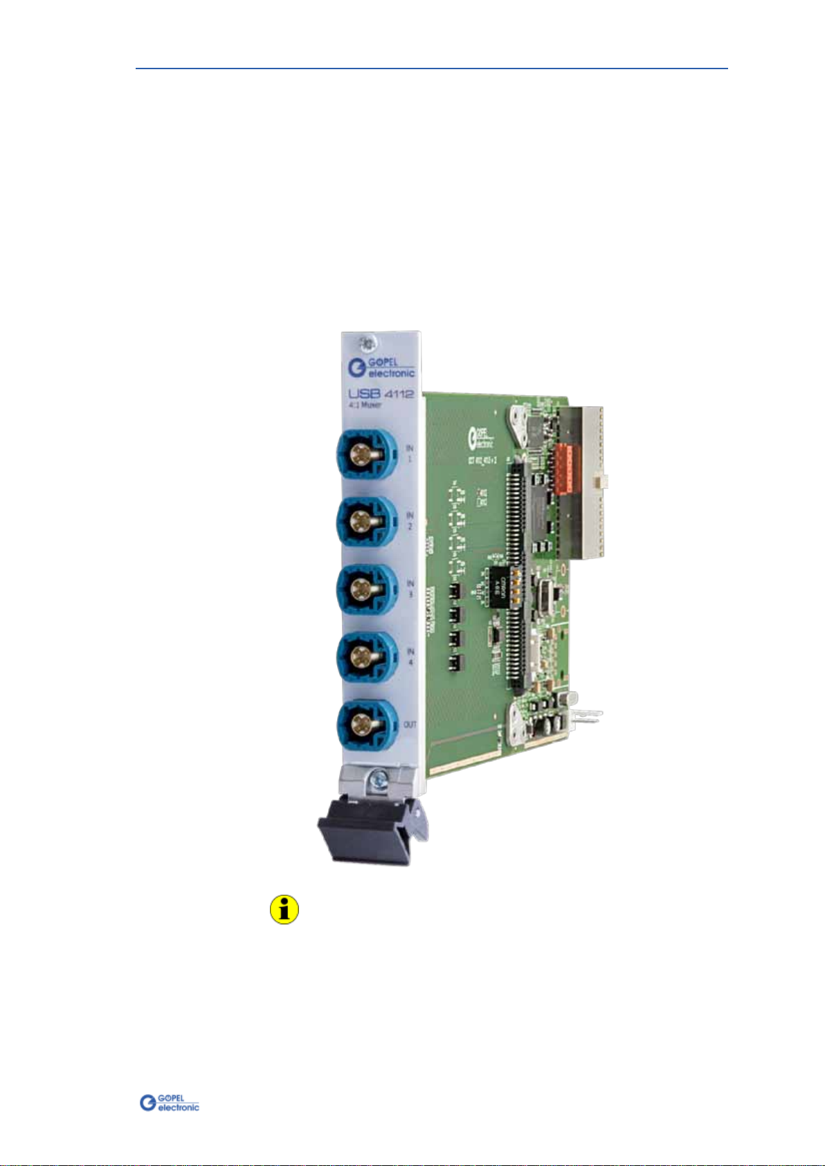
2.3 Construction and Function
The USB 4112 multiplexer board (also used for basicCON 4112)
switches the signal of one of the four LVDS inputs (ANSI TIA/EIA-644)
to the output.
Moreover, the signal is regenerated by the repeaters on the board.
Additionally, a control signal (for example LIN) is multiplexed.
By cascading resp. interconnecting several USB 4112 devices with
each other it is possible to create a 64 to 1 multiplexer.
But we advise not to chain more than three multiplexers in series.
(As otherwise too much jitters would be on the LVDS signal.
Then no error-free transmission can be ensured.)
The board can be controlled via USB or (limited) via switches located
on the board.
All boards have five HF connections at the frontal panel to connect the
LVDS cables.
At the rear side of the USB 4112 board there is a 132 poles backplane
connector for connecting the board in a GOEPEL electronics USB Rack.
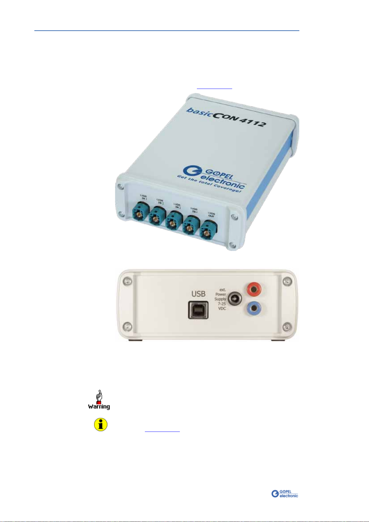
The basicCON 4112 has a USB-B connector and connections for
external power supply.
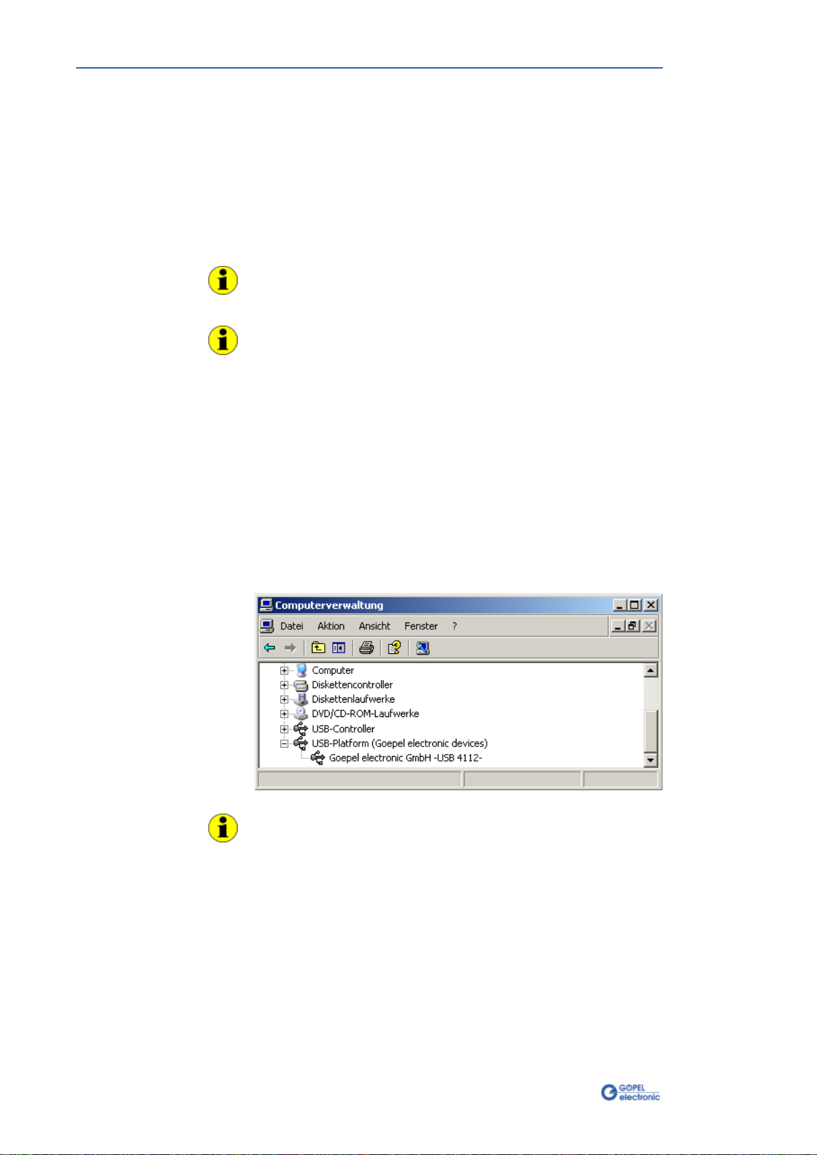
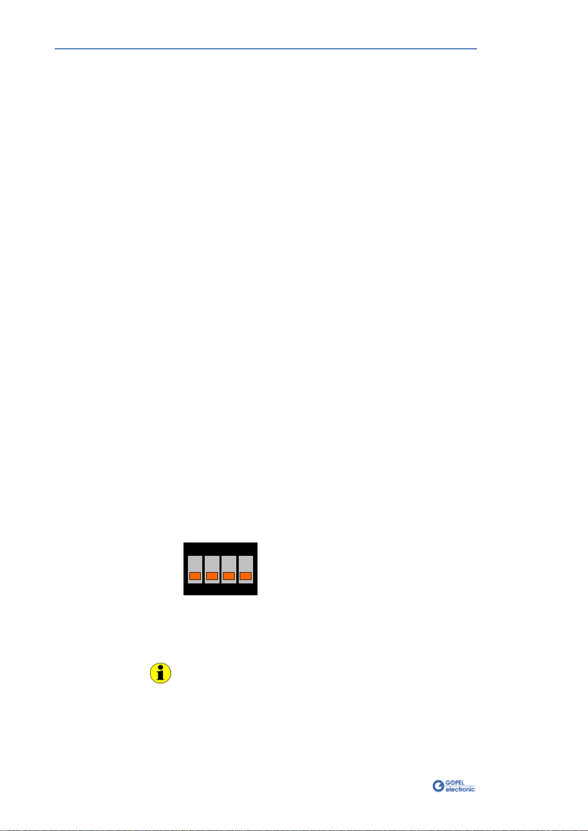
If required, a Hardware Initialization can be carried out by means of
the Switches on the board.
In Figure 2-4 you can see that there is a belonging switch 1..4for
each of the LVDS In1..LVDS In4 input channels.
After switching on, when the Host Mode has not been activated, yet,
the device conducts at most one of the channels to the output as
follows:
If all switches are switched OFF, the LVDS output is also switched
OFF. If one switch is switched ON, the signal of the belonging input is
conducted to the output.
In the case several switches are switched ON, always the switch with
the lowest number has priority. That means, the belonging signal is
conducted to the output.
1 2 3 4
ON
After the activation of the Host Mode, the switches are not active and
control is effected via USB. In the delivery state, all switches are
switched OFF. If required, the switches should be set as needed
before the installation process.
Activate the Host Mode by G-API command
G_Lvds_Multiplexer_HostControlMode_Set.
Please refer to the G-API User Manual regarding this command and
further G-API commands for the control of your
USB 4112/ basicCON 4112 module.
2.3.1 General
2.3.2 Hardware
Initialization
Figure 2-4:
Switches for Initialization

Hardware
USB 4112/ basicCON 4112 – User Manual 2-5
Addressing individual USB 4112boards in the GOEPEL electronicsUSB
Rack or basicCON 4112 devices takes place exclusively according to
the serial numbers: The device with the least serial number is always
the device with the number 1(but counting by considering all other
GOEPEL electronicsUSB devices in the same system).
To improve clarity, we recommend to arrange several USB 4112
boards (if applicable) in the order of ascending serial numbers
in a GOEPEL electronics USB Rack.
The USB 4112 board is supplied via the USB Rack in that it has been
installed.
Power supply for basicCON 4112 can be effected via the USB interface
(as far as it is configured for the required current of about 500 mA).
For operating the basicCON 4112 at passive USB hubs or laptops with
lower power supply, use the two banana females for ext. Power Supply
(red = plus/ blue = minus)
for supplying the device with a voltage of 7-25 VDC.
Alternatively, you may use the female for the delivered AC adaptor
plug with coaxial power plug (2.1 x 5.5mm/ plus polarity inside),
see also Figure 2-3.
Used connector:
Rosenberger D4S20A-40ML5-Z
Connector for connecting cable (recommended):
Rosenberger D4K10A-1D5A5-Z
1
23
41
2 3
41
2 3
41
23
41
23
4
In1 In2 In3 In4 Out
Figure 2-5: Front panel USB 4112
The following table shows the pinout of the LVDS females:
Connection Pin Signal Connection Pin Signal
In 1..4 1 GND Out 1 LVDS-
2 LVDS+ 2 Control
3 Control 3 LVDS+
4 LVDS- 4 GND
2.3.3 Addressing
2.3.4 Power
Supply
2.3.5
Connector
Pinout

Hardware
2-6 USB 4112/ basicCON 4112 – User Manual
2.4 Accessories
The following accessories can be delivered
for USB 4112/ basicCON 4112 devices:
♦LVDS HF connecting cable
(when ordering, please state the required length
and the connector type of the transmitting side)

G-API Programming
USB 4112/ basicCON 4112 – User Manual 3-1
3G-API Programming
The G-API (GOEPEL-API) is the C-programming user interface for
GOEPEL electronics hardware under Windows®.
It provides a wide hardware independent command set for CAN, LIN,
K-Line, MOST, FlexRay, LVDS, ADIO and Diagnostic services.
No matter whether a PXI/ PCI, USB and Ethernet device is used, the
commands remain the same.
The hardware abstraction introduced with the G-API gives the test
application parallel access to the hardware, allowing one application to
access multiple hardware interfaces. As well as multiple applications
can access the same hardware interfaces in parallel.
Another feature introduced by the G-API is the asynchronous
hardware access. This means no blocking execution for pending
firmware commands. The command acknowledgement is provided via
callback mechanism.
Therefore no polling is required from the application.
With the HardwareExplorer GOEPEL electronics provides a hardware
configuration and management tool. Offering users an easy way to
manage their hardware configurations and identifying specific
hardware interfaces by logical names. Using logical interface names in
the application saves from rebuilding the application when porting it to
another interface or controller board, as the interface can be easily
reassigned in the HardwareExplorer.
Furthermore the HardwareExplorer provides a simple means of testing
the interaction between hardware and software by executing the
integrated self-tests.
Please consult the G-API documentation for further information.
This documentation and the installation software are located in the
G-API
folder on the supplied Product CD.


Index
USB 4112/ basicCON 4112 – User Manual i
B
basicCON 4112
Connections...................2-2
G
G-API ...............................3-1
GOEPEL USB Racks............1-1
H
Hardware Explorer.............3-1
Hardware Initialization.......2-4
U
USB 4112
Accessories....................2-6
Addressing ....................2-5
Cascading......................2-4
Characteristics ...............2-3
Connections............2-4, 2-5
Definition.......................2-1
Dimensions....................2-3
Driver Installation...........1-2
Hardware Installation .....1-1
Pinout ...........................2-5
Power supply.................2-5
Stand-alone Device ........2-2
Use...............................2-4
USB cables........................2-3
This manual suits for next models
1
Table of contents
Popular Multiplexer manuals by other brands

Optelecom-nkf
Optelecom-nkf 9252DT Installation and operation manual

Patton electronics
Patton electronics MicroStat II 3022 user manual

Artistic Licence
Artistic Licence railSplit uno user guide

Ultra electronics
Ultra electronics MX420-OP2 installation instructions

Actisense
Actisense PRO-MUX-2 Configuration guide

Pickering
Pickering 40-760 user manual