Gossen MetraWatt AT3-III E User manual

Operating Instructions
AT3-III E Test Adapter
For the Active and Passive Testing of Single and 3-Phase
Electric Devices and Extension Cables in Combination
with SECUTEST.../SECULIFE ST Test Instruments
(M7050…, M7010... and M6930...) 3-349-155-37
17/3.21

2 Gossen Metrawatt GmbH
Device Plugs and Outlets
1 CEE outlet
3P+N+PE, 32 A, 400 V
2 CEE outlet
3P+N+PE, 16 A, 400 V
3 Earthing contact outlet
1P+N+PE, 16 A, 250 V
4 Device outlet for cable testing
1P+N+PE, 10 A, 250 V
5 CEE plug for cable testing
3P+N+PE, 32 A, 400 V
6 CEE plug for cable testing
3P+N+PE, 16 A, 400 V
7 Earthing contact plug for cable testing
1P+N+PE, 16 A, 250 V
8 Device plug for cable testing
1P+N+PE 10 A 250 V
Indicator Displays
9 Mains indicator lamps for L1, L2 and L3
10 Function LED
Self-Test
11 Test key for triggering In (In = residual current)
Connectors for Test Instruments
12 Earthing contact outlet for power supply to test instru-
ments
13 Earthing contact plug with cable, for insertion into the
test socket at the test instrument
14
SECUTEST SIII / SIII+ / SIII+H; SECUTEST S2N+ / S2N+10/
N+w; SECULIFE ST / ST HV
port:
for insertion into sockets 2 and 3 at the test instrument
SECUTEST PRO / ST PRO, SECULIFE ST BASE / ST
BASE25 port and/or feature I01: for insertion into the
sockets
V and COM
at the test instrument
15 Connector sockets for probe cable of the test instru-
ment (for testing cables only)
AT3-III E Power Supply
16 Via connector cable with CEE plug
3P+N+PE, 16 A
Test instruments are not included in the scope of
delivery.
Test Adapter AT3-III E
L3
L2
L1
!
123
4
56
12 7
10
11
9
16
15 15 15
8
13
14
15

Gossen Metrawatt GmbH 3
Table of Contents
Page
1 Applications ...............................................3
2 Safety Precautions .....................................4
3 Connecting the Test Adapter to the Mains 5
4 Connecting a Device Under Test
to the Test Adapter ....................................5
5 Testing Devices .........................................5
5.1 Measuring Protective Conductor Resistance ...5
5.2 Measuring Insulation Resistance and
Equivalent Leakage Current ..........................6
5.3 Measuring Protective Conductor Resistance
with the Residual Current Method
(except for SECUTEST BASE / BASE10 /
ST BASE / ST BASE10) .................................6
5.4 Testing of Differential Current during
Automatic Testing per Test Standard .............8
5.5 High-Voltage Test ........................................8
6 Testing Extension Cables ...........................8
6.1 Measuring Protective Conductor Resistance ...8
6.2 Measuring Insulation Resistance ...................8
6.3 Functional Testing for Short-Circuits,
Interruptions and Reversed Conductors of
Cables L1, L2, L3 and N ...............................9
7 Self-Test ..................................................11
8 Technical Data .........................................12
9 Maintenance ............................................13
10 Repair and Replacement Parts Service,
Calibration Center and Rental Instrument
Service .....................................................13
11 Product Support .......................................13
1 Applications
The portable AT3-III E test adapter (Z745S) is
used for measuring and testing single and 3-
phase electrical devices and extension cables in
combination with the test instruments with the fol-
lowing article numbers (basic device):
M7010 (SECUTEST SIII / SIII+ / SIII+H;
SECUTEST S2N+ / S2N+10 / N+w)
M6930 (SECULIFE ST / ST HV)
M7050 (SECUTEST BASE / BASE10 / PRO;
SECUTEST ST BASE / ST BASE10 /
ST PRO;
SECULIFE ST BASE / ST BASE25)
In these operating instructions, suitable instru-
ments are referred to as test instrument for short.
Testing must be performed by a qualified electri-
cian with an appropriate test instrument after
repair or modification, and is also required for peri-
odic testing per DIN VDE 0105/0701-0702.
According to these regulations, testing must be
performed for protective conductor resistance,
insulation resistance, equivalent leakage current,
residual current and contact current, as well as for
the absence of voltage depending upon the type
of device under test.
The test adapter, in combination with the test instru-
ment, allows for
– the passive testing:
• of protective conductor resistance
• of insulation resistance
• of protective conductor current by means of
equivalent leakage current method
• of dielectric strength (HV test up to 1.5 kV)1
• at extension cables:
– testing for conductor short-circuiting,
– testing for conductor interruption
and additionally at 3-phase extension cables:
– testing for conductor reversal on L1, L2
and L3 for the determination of clockwise
rotation.
• with protection by means of electronic resid-
ual current monitoring with mains shutdown
at DUTs with residual current of more than
20 mA and visual error messages
– the active testing:
(nominal current 16 A – maximum 20 A current
consumption by DUT, also at the 32 A test
socket)
• of protective conductor current 1 3
– by means of the differential current
method (requires voltage measurement
sockets at the test instrument 2)
– by means of direct method (requires
direct measurement of protective con-
ductor current at the test instrument)
• of contact current 3
1Only if the utilized test instrument is capable of perform-
ing this measurement
2Not with SECUTEST BASE / BASE10 or without fea-
ture I01, respectively
3Please note that the pole reversal function is not active
with the applied test instrument if you use the AT3-IIIE
adapter for the testing of single-phase test objects
(socket 3 / earthing contact plug). In this case, all leak-
age current measurements must be performed manu-
ally in both pole directions.

4 Gossen Metrawatt GmbH
Measurement results are displayed at the test
instrument.
Note!
The AT3-III E test adapter is equipped with
electronic error monitoring which discon-
nects the device under test from the mains in
the event of fault currents of greater than
18 mA.
2 Safety Precautions
The test adapter has been manufactured and
tested in accordance with the following regula-
tions:
IEC 61010-1/DIN EN 61010-1/VDE 0411-1 “Reg-
ulations for electronic testers and controllers, part
1: Safety measures for electrical measuring instru-
ments”
DIN VDE 0404 “Devices for technical safety test-
ing of electrical equipment, parts 1 and 2.”
EN 61326-1 product standard EMC requirements.
Safety is only assured for the user and the test
adapter when used for its intended purpose in
combination with the test instruments mentioned
in chapter 1 "Applications".
In order to maintain flawless technical safety con-
ditions, and to assure safe use, it is imperative that
you read these operating instructions thoroughly
and carefully before placing your test adapter into
service, and that you follow all instructions con-
tained herein.
Due to the fact that all tests performed with the AT3-
III E must be executed in combination with a test instru-
ment mentioned in chapter 1 "Applications", you must
also read the safety precautions and liability limitations
included in the operating instructions for this instru-
ment.
Observe the following safety precautions:
Attention!
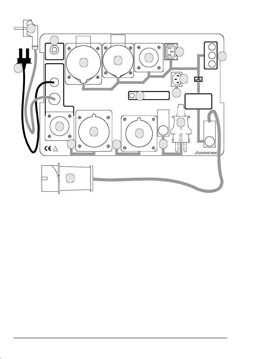
!If the red LED (10) remains lit even after
the AT3-III E has been disconnected from
the mains and connected once again, the
test adapter is defective.
If this is the case,
the AT3-III E must be removed from service
and repaired before it is used again.
• In order to assure compliance with technical
safety requirements, the AT3-III E test adapter
should only be repaired by the manufacturer.
• The AT3-III E must be disconnected from the
mains and from the test instrument before it is
opened.
Measurements within electrical systems are prohibited!
• The test adapter’s 16 A CEE 3P+N+PE (16)
plug may only be connected to 230/400 V
50 Hz mains power. In order to avoid unde-
sired shutdown of defective devices under
test, the electrical circuit for the device under
test should be separately fused.
• Before connecting the AT3-III E to the mains,
the test instrument must first be connected to
the AT3-III E.
Attention!
!Tests during which mains power is ap-
plied may only be selected with the func-
tion selector switch at the test instrument
after safety class I devices under test
have passed the protective conductor
test. If the protective conductor is defec-
tive (interruptions / reversed conductors),
line voltage may be present at the hous-
ing of a defective device under test, at the
earthing contacts of the test plugs (4 – 7)
and at the safety socket (15)!
• For REASONS OF SAFETY, the device under test
must be turned off before switching to
“MAINS” so that dangerous devices under
test (e.g. a circular saw) can only be switched
on intentionally.
•Measurement with line voltage:
Exposed parts may conduct dangerous touch
voltage during testing. Do not touch under
any circumstances! Use a special cover in
order to avoid touch contact.
Under certain circumstances, full mains dis-
connection at the device side may not occur
in the event of leakage current, or it may be
inadequate to meet the requirements of a
PRCD.
Work only at a protected workstation, i.e. use
enhanced touch protection, use a 30 mA
RCD and wear personal safety equipment
(PSE).
• Be prepared for the occurrence of unex-
pected voltages at devices under test (e.g.
due to charged capacitors).
• Before connecting the device under test to
the test adapter, subject it to a thorough
VISUAL INSPECTION first. Damaged devices
under test must be repaired prior to testing.
• Only extension cables which have been
plugged into the test outlets (1-4) at the test
adapter may be connected to the device
plugs (4- 7) at the test adapter.
• Due to test adapter design in accordance with
DIN VDE 0404, the “PE” contacts at the out-
lets (1-4) are only connected to the mains pro-
tective conductor when the test instrument
has been set for testing with mains power.

Gossen Metrawatt GmbH 5
• If the test adapter and/or its connector cables
demonstrate visible damage, no longer func-
tion, have been stored for a lengthy period of
time under unfavorable conditions or have
been subject to excessive stress during trans-
port, it must be assumed that hazard-free
operation is no longer possible. Remove the
AT3-III E from service and secure it against
inadvertent use in such cases.
Opening of Equipment / Repair
The equipment may be opened only by authorized
service personnel to ensure the safe and correct
operation of the equipment and to keep the war-
ranty valid.
Even original spare parts may be installed only by
authorized service personnel.
In case the equipment was opened by unautho-
rized personnel, no warranty regarding personal
safety, measurement accuracy, conformity with
applicable safety measures or any consequential
damage is granted by the manufacturer.
Meanings of Symbols on the Instrument
Warning concerning a point of danger
(Attention: observe documentation!)
European conformity label
This device may not be disposed of
with the trash. Further information
regarding the WEEE mark can be
accessed on the Internet at
www.gossenmetrawatt.com by
entering the search term ’WEEE’.
3 Connecting the AT3-III E Test Adapter to the
Mains
The following connections must first be estab-
lished before connecting the test adapter to the
mains:
a) Insert the mains plug from the test instrument
into the earthing contact outlet (12) at the
AT3-III E.
b) Insert the earthing contact plug (13) from the
AT3-III E into the test socket at the test instru-
ment.
c) In order to measure protective conductor cur-
rent, connect the test instrument port (14) of
the AT3-III E into sockets 2 and 3 at the
SECUTEST SIII / SIII+ / SIII+H; SECUTEST
S2N+ / S2N+10 / N+w; SECULIFE ST / ST
HV or into sockets V and COM at the SECUT-
EST PRO; SECUTEST ST PRO; SECULIFE ST
BASE / ST BASE25.
d) In order to test extension cables, insert the
test probe at the end of the probe cable of the
test instrument into the socket (15) at the
AT3-III E.
Connect the test adapter to 230/400 V mains
power. The test adapter now performs a self-test.
If the tester is intact, the red LED lights up briefly.
4 Connecting a Device Under Test
to the Test Adapter
After the device under test has passed a visual
inspection and before connecting it to the appro-
priate plug or socket at the test adapter, as well as
before each new test, the test instrument must be
returned to its initial setting depending upon the
type of test.
Connect the device under test to the test adapter
and switch all of its functions on, making sure
that, for example, thermostat contacts are closed
etc. Always MEASURE PROTECTIVE CONDUC-
TOR RESISTANCE first for safety class I devices,
because if the protective conductor is defective,
insulation resistance, equivalent leakage current
and protective conductor current cannot be mea-
sured, and high-voltage testing cannot be per-
formed.
5 Testing Devices
Perform testing in accordance with the operating
instructions included with the test instrument!
Observe the following instructions when using the test
instrument in combination with the AT3-III E during
automatic test sequence :
For some test sequences, a suitable AT3 adapter
must be used as connection type.
5.1 Measuring Protective Conductor Resistance
The clip or the test probe at the end of the probe
cable from the test instrument must be connected
to the housing of the device under test such that
good contact is assured.
Note!
Connector cable (13) resistance is 0.07 . In
order to compensate for this error, proceed
as described in the operating instructions
included with the test instrument under Indi-
vidual Measurements Protective Conduc-
tor Resistance Zero Balancing.
If the AT3-III E is out of use for a prolonged period
of time, the earthing contact faces of the plug-
and-socket connectors and the connecting plug
(13) may corrode, thus leading to slightly elevated
resistance measurement values. In this case, plug
and unplug the connections several times until the
expected values are reached again.
!

6 Gossen Metrawatt GmbH
5.2 Measuring Insulation Resistance and Equivalent
Leakage Current
L1, L2, L3 and N (short-circuited) are measured
against PE during insulation testing.
5.3 Measuring Protective Conductor Resistance with
the Residual Current Method (except for SECUT-
EST BASE / BASE10 / ST BASE / ST BASE10)
The DUT is placed into operation during residual
current measurement. The L1, L2 and L3 mains
lamps light up at the AT3-III E during this test.
This measurement may not be performed on safety
class I devices until after the protective conductor test
has been passed in accordance with chapter 5.1.
➭Turn off the device under test.
➭Select the IL-DI measurement setting at the
test instrument.
➭The line contactor switches mains power to
the test outlets (1 – 4) at the AT3-III E. Signal
lamps L1, L2 and L3 indicate the presence of
line voltage.
➭Now switch on the DUT (as described in
chapter 2).
Contact current is measured by means of residual
current measurement for safety class II devices,
and safety class I devices with accessible con-
ductive parts which are not connected to the pro-
tective conductor. Contact all accessible conduc-
tive parts at the device under test with the test
probe at the end of the probe cable form the test
instrument to this end.
These measurements must be performed with the
plug in both positions for DUTs with earthing con-
tact plugs!
Note!
This test must be performed in accordance
with the specified test sequence. Mains
power must be indicated by signal lamps L1, L2
and L3 (9) before switching the device under test
on.
The test outlets (1 – 4) are disconnected
from the mains by the safety shutdown func-
tion included with the AT3-III E for devices
under test with fault currents of greater than
18 mA during measurement of protective
conductor current with residual current.
Mains power may be disconnected if the
AT3-III E is used in systems protected with
RCCBs rated less than 30 mA. Mains signal
lamps L1, L2 and L3 (9) go out. The function
LED (10) blinks.

Gossen Metrawatt GmbH 7
Disconnect the AT3-III E from the mains to reset.
Reconnect the AT3-III E to the mains. The test
adapter is once again ready for use after a brief
self-test.
The short-circuit test displayed at the test instru-
ment cannot be performed due to safety imped-
ances which have been integrated into the AT3-
III E for testing 3-phase devices.
Figure 1 Connecting Single and 3-Phase Devices to the AT3-III E and the test instrument
230/400 V 50 Hz
test adapter AT3-III E
L3
L2
L1
!
SECUTEST
13
230/400 V 50 Hz
test adapter AT3-III E
L3
L2
L1
!
SECUTEST
13
COM V 1
SECUTEST SIII / SIII+ / SIII+H;
SECUTEST S2N+ / S2N+10 / N+w)
SECULIFE ST / ST HV
SECUTEST PRO; SECUTEST ST PRO
SECULIFE ST BASE / ST BASE25

8 Gossen Metrawatt GmbH
5.4 Testing of Differential Current during Automatic
Testing per Test Standard
SECUTEST SIII / SIII+ / SIII+H; SECULIFE ST / ST HV:
➭Initiate the standard-specific setup.
➭Select „Sequence“ and deactivate the auto-
matic test method.
During testing according to standard, a menu
appears which proposes two options, i.e. equiva-
lent leakage current and differential current.
➭Select „Differential current“.
SECUTEST S2N+ / S2N+10 / N+w:
➭Select switch position „active“ here.
Line voltage is applied to the DUT via the AT3-III E
tester. The differential current of the DUT is mea-
sured while allowing for a function test of the DUT.
SECUTEST PRO / ST PRO; SECULIFE ST BASE /
ST BASE25 and/or feature I01:
➭Select connection type AT3-adapter for I PE mea-
surement in the setup of the test sequence.
5.5 High-Voltage Test
Caution: High-Voltage!
Prior to performing the test remove the
probe including probe tip from sockets 4
and 5 of the test instrument. Do not touch
the DUT, the device plug and the earthing
contact cable of the AT3-III E during the
voltage test.
Do not unplug the AT3-III E connector
cable (13) from the test socket at the test
instrument: the device under test may still
be charged, and high voltage may be
present at the earthing contact plug.
During this test, L1, L2, L3 and N (short-circuited)
are measured against PE with the preset high volt-
age (max. 1.5 kV!).
Please observe all additional safety precautions
on performing the test as well as the note on the
exclusion of liability in the operating instructions of
the test instrument.
6 Testing Extension Cables
The SECUTEST port (14) may remain connected
to sockets 2 and 3 at the test instrument during
this test. Perform testing in accordance with the
operating instructions included with the test
instrument!
Observe the following instructions when using the
test instrument in combination with the AT3-III E:
The test probe at the end of the probe cable of the
test instrument must first be connected to the
respective socket (15) (probe 1 to 4) of the associ-
ated plug at the AT3-III E. In order to test, only
connect the plug and socket at the ends of the
respective extension cable to be tested to the
associated device plug and socket at the AT3-
III E. The associated connection diagrams are
shown on the following pages.
SECUTEST SIII / SIII+ / SIII+H; SECULIFE ST / ST HV:
Select the following test sequence from the initial
window at the test instrument:
Extension cable: “X” WITH EL1
Note!
Testing cables by means of the AT3-III E is
only possible with this setting.
SECUTEST S2N+ / S2N+10 / N+w:
➭Select the following switch position:
VDE 0701-0702
➭Select EL1 as connection type.
SECUTEST PRO / ST PRO; SECULIFE ST BASE /
ST BASE25 and/or feature I01:
➭Select AT3-III E as connection type.
6.1 Measuring Protective Conductor Resistance
Testing is performed according to the instructions
included in chapter 5.1.
6.2 Measuring Insulation Resistance
L1, L2, L3 and N (short-circuited) are measured
against PE during insulation testing. Due to good
cable insulation, a value of 2 M should not be
significantly exceeded.
Note!
In conductors with control lamp (usually glow
lamp in the switch), the result of the continu-
ity test for L and N may be distorted by the
additional resistance of the glow lamp.
In case of doubt, we recommend performing
a continuity test for L and N by means of
resistance measurement (R-PE or R-ISO):
e.g. SECUTEST SIII / SIII+ / SIII+H; SECU-
LIFE ST / ST HV; SECUTEST S2N+ /
S2N+10 / N+w: R-PE between probe and
socket 3 or R between socket 1 and 2.
SECUTEST PRO / ST PRO; SECULIFE ST
BASE / ST BASE25:
R-PE between probe 1 and probe 2.
SECUTEST BASE / BASE10 / ST BASE / ST
BASE10:
R-PE between probe 1 and measurement
cable at the earth contacts of the test socket
(test type PE(PD)-P1).

Gossen Metrawatt GmbH 9
6.3 Functional Testing for Short-Circuits, Interrup-
tions and Reversed Conductors of Cables L1, L2,
L3 and N
Testing of single-phase cables is performed as
described in the instructions included with the test
instrument under (optional EL1 test adapter). The
EL1 test adapter accessory is included in the AT3-
III E as a subassembly.
Note!
While testing the continuity of single-phase
extension cables, AT3-III E may NOT be sup-
plied with line voltage.
While testing the continuity of 3-phase exten-
sion cables, AT3-III E must be connected
with line voltage.
Note: When testing device cable connections (socket
4/plug 4) polarity L/N is not being checked.
Testing of 3-phase cables is the same, except that it
also includes an additional test for reversing of
conductors L1, L2, L3 and N.
3-phase cables have only passed testing for
short-circuits, interruptions and reversed conduc-
tors (clockwise rotation) if the following test result
appears: “Cable OK”.
Messages such as “interruption / short-circuit”
always indicate that the cable is defective. If this is
the case, conductors L1, L2, L3 and N may also
be reversed. The actual defect must be deter-
mined.
Figure 2 Connecting Single Phase Extension Cables to the AT3-III E and the
SECUTEST SIII / SIII+ /
SIII+H; SECUTEST S2N+ / S2N+10 / N+w; SECULIFE ST / ST HV
SECUTEST
34
4
4
3
230 V 50 Hz

10 Gossen Metrawatt GmbH
Figure 3 Connecting 3-Phase Extension Cables to the AT3-III E and the
SECUTEST SIII / SIII+ / SIII+H;
SECUTEST S2N+ / S2N+10 / N+w; SECULIFE ST / ST HV
Figure 4 Connecting Single Phase Extension Cables to the AT3-III E and the SECUTEST BASE / BASE10
/ PRO; SECUTEST ST BASE / ST BASE10 / ST PRO; SECULIFE ST BASE / ST BASE25
SECUTEST
1
2
21
230/400 V 50 Hz
SECUTEST
34
4
4
3
230 V 50 Hz
1

Gossen Metrawatt GmbH 11
Figure 5 Connecting 3-Phase Extension Cables to the AT3-III E
and the SECUTEST BASE / BASE10 /
PRO; SECUTEST ST BASE / ST BASE10 / ST PRO; SECULIFE ST BASE / ST BASE25
7 Self-Test
Because it is so easy to perform, the self-test should
be conducted before each use of the AT3-III E.
Please be careful to ensure that the case of the
AT3-III E is not being contacted with devices
under PE or earth potential during the self-test.
Performing the Protective Conductor Test
➭
Insert the mains plug from the
test instrument
into
the earthing contact outlet (12) at the AT3-III E.
➭The earthing contact plug (13) and the
test instrument port (14) of the AT3-III E may
not
be plugged into the test instrument.
➭Connect the AT3-III E to mains power.
➭Set the test instrument to the protective con-
ductor test individual measurement (RSL/RPE).
➭Contact protective conductor potential at the
mains system which is supplying power to the
AT3-III E with the test probe at the end of the
probe cable from the test instrument, e.g. at
the earthing contact of an earthing contact
outlet. If an excessively high value or interrup-
tion is indicated, the protective conductor is
interrupted.
The AT3-III E test adapter must be disconnected
from the mains, and the error in the electrical sys-
tem or the test adapter must be corrected. The
AT3-III E is equipped with a “Trigger In” test key in
order to allow for testing the included In safety
shutdown function at any time.
Performing the In Self-Test
➭Remove the device under test
(device or extension cable).
➭Set the test instrument to individual measure-
ment.
➭Test instrument: Select the “DI current” sub-
menu (residual current).
➭Signal lamps L1, L2 and L3 indicate the pres-
ence of line voltage.
➭Activate the “Trigger In” key (11).
➭The AT3-III E disconnects mains power from
the outlets (1 – 4).
➭Signal lamps L1, L2 and L3 go out.
➭The function LED (10) blinks.
Disconnect the AT3-III E from the mains to re-
set. Reconnect the AT3-III E to the mains.
The test adapter is once again ready for use
after a brief self-test.
Note!
If mains power is not switched during this
test, the fuses in the AT3-III E may have
blown. If the AT3-III E still does not function
correctly after replacing the fuses, it must be
removed from service and repaired. Mea-
surement is no longer possible!
SECUTEST
1
2
21
230/400 V 50 Hz
1

12 Gossen Metrawatt GmbH
8 Technical Data
Article Number
Z745S
Residual Current Measuring Function
Measuring Range 0 20 mA
Transformation Ratio 1 V per 10 mA
Intrinsic Uncertainty (5%
of rdg.
+ 0.05 mA)
Nominal Ranges of Use
Line Voltage
L1/L2/L3/N 207 253 V AC
Frequency 49 51 Hz
Temperature 0 °C +40 °C
Line Voltage
Waveshape sinusoidal
Reference Conditions
Ambient Temperature +23 C 2 K
Relative Humidity 50% 5%
Line Voltage 230 V/400 V 10%
Frequency
of Measured Quantity 50 Hz 0.2%
Ambient Conditions
Operating Temperatures –10 + 40 C
Storage Temperatures –25 + 60 C
Humidity max. 75%, no conden-
sation allowed
Elevation up to 2000 m
Power Supply
Nominal Line Voltage
3~230/400 V/50 Hz/CAT II
Connection only permissible with overload protec-
tion device In = 16 A I2 1.45 In
Electrical Safety
Pollution degree 2
Safety Class I per DIN EN 61140/
VDE 0140-1
Residual Current
Shutdown (4-pole) at IdN = 14,6 mA,
ta = 82 ms
Device Fuses F0315 L250V
5 x 20 T32mA L 250 V
DIN EN 60127-2
Electromagnetic Compatibility
Intrinsic Uncertainty
EN 61326-1:2013 class B
Intrinsic Uncertainty EN 61326:2013
Mechanical Design
Protection case: IP40
terminals: IP20
Extract from table on the meaning of IP codes
Dimensions 405 x 300 x 220 (mm)
with lid
Weight approx. 6.7 kg
Note!
Observe the technical data of the respective
test instrument.
IP XY
(1st digit X)
Protection against
foreign object entry
IP XY
(2 nd digit Y)
Protection against the
penetration of water
0 not protected 0 not protected
1 50.0 mm dia. 1 vertically falling
drops
2 12.5 mm dia. 2 vertically falling
drops with enclo-
sure tilted 15
3 2.5 mm dia. 3 spraying water
4 1.0 mm dia. 4 splashing water

Gossen Metrawatt GmbH 13
9 Maintenance
Front Panel / Housing
No special maintenance is required for the hous-
ing. Keep outside surfaces clean. Use only a cloth
for cleaning, which has been slightly dampened
with water. Avoid the use of cleansers, abrasives
and solvents.
Note!
According to DIN VDE 0701-0702, measur-
ing instruments used for periodic testing
must be tested and calibrated in accordance
with the manufacturer’s specifications on a
regular basis. Depending upon usage, the
manufacturer recommends an interval of 1
to 3 years for this test instrument.
Device Return and Environmentally Compatible Disposal
The instrument is a category 9 product (monitor-
ing and control instrument) in accordance with
ElektroG (German Electrical and Electronic Device
Law). This device is subject to the WEEE directive.
Furthermore, we make reference to the fact that
the current status in this regard can be accessed
on the Internet at www.gossenmetrawatt.com by
entering the search term WEEE.
We identify our electrical and electronic
devices in accordance with WEEE 2012/
19/EU and ElektroG with the symbol
shown to the right per DIN EN 50419.
These devices may not be disposed with the
trash. Please contact our service department
regarding the return of old devices.
10 Repair and Replacement Parts Service, Calibra-
tion Center and Rental Instrument Service
If required please contact:
GMC-I Service GmbH
Service-Center
Beuthener Straße 41
90471 Nürnberg • Germany
Phone: +49 911 817718-0
Fax: +49 911 817718-253
E-Mail [email protected]
www.gmci-service.com
This address is only valid in Germany.
Please contact our representatives or subsidiaries
for service in other countries.
11 Product Support
If required please contact:
Gossen Metrawatt GmbH
Product Support Hotline
Phone: +49 911 8602-0
Fax: +49 911 8602-709
E-Mail [email protected]

© Gossen Metrawatt GmbH
Edited in Germany Subject to change without notice / Errors excepted A PDF version is available on the Internet
All trademarks, registered trademarks, logos, product names, and company names are the property of their respective owners.
Gossen Metrawatt GmbH
Südwestpark 15
90449 Nürnberg • Germany
Phone +49 911 8602-111
Fax +49 911 8602-777
E-Mail [email protected]
www.gossenmetrawatt.com
Other manuals for AT3-III E
2
This manual suits for next models
1
Table of contents
Other Gossen MetraWatt Adapter manuals

Gossen MetraWatt
Gossen MetraWatt GEOHM ERP-1 User manual

Gossen MetraWatt
Gossen MetraWatt USB HIT User manual

Gossen MetraWatt
Gossen MetraWatt BD 232 User manual

Gossen MetraWatt
Gossen MetraWatt BD 232 User manual

Gossen MetraWatt
Gossen MetraWatt AT3-II S User manual

Gossen MetraWatt
Gossen MetraWatt AT3-III E User manual

Gossen MetraWatt
Gossen MetraWatt A3-32 User manual

Gossen MetraWatt
Gossen MetraWatt Z250I User manual