manuals.online logo
Brands
  1. Home
  2. •
  3. Brands
  4. •
  5. Gost
  6. •
  7. Marine Equipment
  8. •
  9. Gost Nav-Tracker 3.0 User manual

Gost Nav-Tracker 3.0 User manual

Nav-Tracker 3.0
1
Installation Review
The Nav-Tracker 3.0 system is an Inmarsat m2m battery backed security
position and alerting terminal. There are seven components to the entire
system, the Nav-Tracker antenna, antenna mounting bracket, 3.0 Control Unit,
alert push button, antenna cable, I/O Cable, and a Power Cable (Figure 1).
Follow the instructions and location suggestions off all the components
identified in this manual.
3.0 Control Unit Location
The Control Unit provides the power/ battery backup to the antenna, Input/
Output control (I/O), and power supply input. Consider the following when
deciding on a location:
Keep it accessible but not visible. The Enclosure is IP67 rated,
though it is best not to mount it in an exposed area where it is more
susceptible to water spray or tampering
Locate it where the three cables included with it can easily be run
to its location and allow space for cable plug ins on the side
identified in Figure 2
Figure 2
Nav-Tracker Antenna Location
Locate the antenna a minimum of two feet away from metallic
obstructions such as hand rails, rod holders and cleats.
Choose a location that is not directly under or near radar arrays to
prevent possible interferences.
Make sure that the underside of the antenna is accessible to
connect the antenna cable. Leave some room underneath the
antenna to provide space for the connection.
Mount on a flat horizontal surface.
The antenna communicates its data to the Inmarsat® Geostationary
based satellite network. As a general rule, a clear line of site
towards the equator is needed.
Whenever possible, dry run the installation procedure and test the
location beforehand.
Think Security. The location of the antenna is critical to proper
system operation and should be toughly scrutinized.
See installation picture on included starboard shelf and diagram of
suggested locations in Figure 3.
Figure 3
Arm/ Disarm Pushbutton
The Alert pushbutton should be located in discreet but accessible location.
This button will arm the geofence when latched in and disarm the geofence
pushed out.
Figure 4
Installation
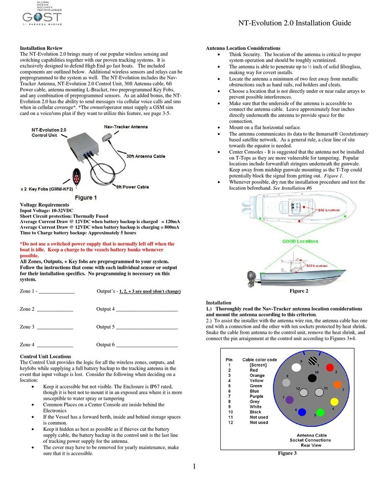
1.) Thoroughly read the Nav-Tracker antenna, 3.0 control unit, and
Alert Pushbutton location considerations and mount the antenna
according to this criterion.
2.) To keep the antenna cable runs easier, the antenna cable has one end with
a connection and the other with ten sockets protected by heat shrink. Make
sure the end that needs to be connected at the 3.0 Control unit side. Install the
antenna in the one of the open locations suggested in Figure 3.
3.) Place the end of the antenna cable that is complete at the antenna and
run the cable from antenna to the 3.0 control unit, remove the heat shrink, and
connect the pin arraignment at the control unit according to Figures 4+5.
Nav-Tracker 3.0
2
Figure 4
Figure 5
4.) Open the 3.0 control unit by unscrewing the four Philips head screws in
the rear (Figure 6)
Figure 6
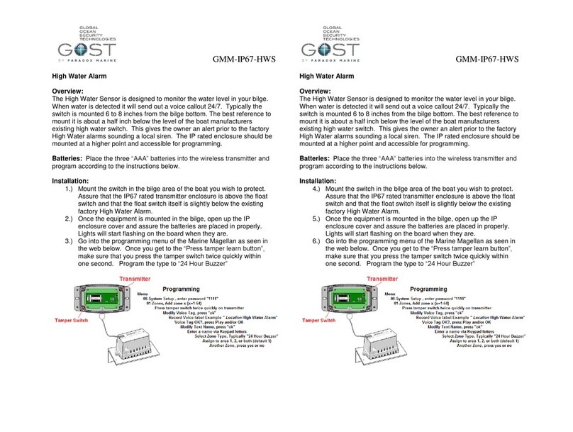
5.) Plug in the loose battery backup connector to board. It will only go on in
one direction and will lock into place (Figure 7). A Red LED should come on
board once this is complete.
Figure 7
6.) Re secure the cover onto the back cover making sure that the foam piece
on the back cover is on the same side as the battery (Figure 8). Then fasten
the four screws back in.
Figure 8
7.) Mount the control unit and plug in the power cable into the “Power” input
Mount the control unit according to the 3.0 Control Unit Locations suggested
.
8.) Connect the Power Cable’s black wire to a negative DC source and the red
wire to a Positive 12 or 24 VDC supply.
9.) Connect the antenna cable into the “Antenna” plug of the 3.0 control unit..
10.) Now perform a visual check of the antenna. There is a light at the base of
the antenna in Figure 9. Assure that the antenna is rotated to a position where
the light is visible to the installer. When the unit is first powered up it will
initially blink red, then gradually change to orange, and then green. The
antenna should be blinking green within about five minutes of startup. If it
does not, confirm that the signal is not getting blocked and adheres to the
location considerations. Also see Table 1 with light sequence.
Figure 9
11.) The last component to hook up on the system is the “arm / disarm” push
button. This button is a latching switch. When it is pushed in it is a closed
circuit and is sends out a “Geofence Armed” message. When it is pushed out,
it is an open circuit and the a “Geofence Disarmed” is sent. Connect the two
wires coming out of the push button two the two wires coming out of the I/O
cable. It does not matter which direction the two cables are connected (non-
polar). It is suggested that you use a heat shrink butt connector that is
properly crimped. See Figure 10 below.
Figure 10
12.) With the Push Button alert now connected to the I/O cable, now connect
the other side of the I/O cable into the middle “I/O” connection on the 3.0
Control Unit.
13.) The system is now installed. See User guide for instructions on
operation.

Other Gost Marine Equipment manuals

Gost MG-Navtracker User manual

Gost

Gost MG-Navtracker User manual

Gost GMM-IP67-HWS User manual

Gost

Gost GMM-IP67-HWS User manual

Gost NT-Evolution 2.0 User manual

Gost

Gost NT-Evolution 2.0 User manual

Popular Marine Equipment manuals by other brands

Harken 3387 instructions

Harken

Harken 3387 instructions

ALBIN PUMP Marine Defroster 9 kW Instructions for use

ALBIN PUMP

ALBIN PUMP Marine Defroster 9 kW Instructions for use

Marport Pro Trident XXL bottle Maintenance manual

Marport

Marport Pro Trident XXL bottle Maintenance manual

Moog Tritech Micron Gemini product manual

Moog

Moog Tritech Micron Gemini product manual

Vimpex Fire-Cryer Plus Application guide

Vimpex

Vimpex Fire-Cryer Plus Application guide

E2S A112N Instructions/service manual

E2S

E2S A112N Instructions/service manual

Wet Sounds XS-808 owner's manual

Wet Sounds

Wet Sounds XS-808 owner's manual

Raymarine ST60 Tridata Setup & operation

Raymarine

Raymarine ST60 Tridata Setup & operation

Nexus 21 Autopilot Installation and operation manual

Nexus 21

Nexus 21 Autopilot Installation and operation manual

Raymarine H6 owner's manual

Raymarine

Raymarine H6 owner's manual

Global Fire Equipment Valkyrie Vox C quick start guide

Global Fire Equipment

Global Fire Equipment Valkyrie Vox C quick start guide

Simrad EQ 50 Maintenance manual

Simrad

Simrad EQ 50 Maintenance manual

COBHAM SAILOR 6282 user manual

COBHAM

COBHAM SAILOR 6282 user manual

MOFLASH SIGNALLING SD125 Series INSTALLATION & TECHNICAL INFORMATION

MOFLASH SIGNALLING

MOFLASH SIGNALLING SD125 Series INSTALLATION & TECHNICAL INFORMATION

Venitem DOGE AS1 Technical manual

Venitem

Venitem DOGE AS1 Technical manual

Raymarine i60 wind Installation & operation instructions

Raymarine

Raymarine i60 wind Installation & operation instructions

Ocean Signal OS-702S-03933 user manual

Ocean Signal

Ocean Signal OS-702S-03933 user manual

Furuno FCV-585 Operator's manual

Furuno

Furuno FCV-585 Operator's manual

manuals.online logo
manuals.online logoBrands
  • About & Mission
  • Contact us
  • Privacy Policy
  • Terms and Conditions

Copyright 2025 Manuals.Online. All Rights Reserved.