Vimpex Fire-Cryer Plus User guide

Fire-Cryer Plus®
The Fire-Cryer® range of voice sounders was first introduced to the market by Vimpex in
1999. The continuing research and development of voice sounders by Vimpex Limited has
kept us as the market leader in performance, technical capability and diversity of range and
applications.
The Fire-Cryer® is, in its simplest form, an electronic sounder capable of delivering clear,
intelligible and synchronised voice messages and tones.
Requiring just 2 wires, a positive and negative, to deliver 24VDC to any one of the Fire-
Cryer® family of voice sounders it can be retrofitted to existing conventional sounder circuits.
The cost savings of using existing wiring can be considerable.
With the use of proprietary interfaces the Fire-Cryer® can also be easily integrated onto
addressable loops and is approved by Hochiki and Apollo.
The latest range of Fire-Cryer® voice sounders is now capable of holding and broadcasting up
to 7 different messages and any number of tones. These messages and tones are
programmed into each sounder head.
This latest range of Fire-Cryer® voice sounders is now known as Fire-Cryer Plus®
The Fire-Cryer Plus® Range of Voice Sounders
Mini Fire-Cryer Plus® A white base sounder for installation under ceiling mounted
detectors.
Part Ref. FC3/C
Standard Fire-Cryer Plus® A red wall mounted sounder supplied with or without a
beacon. Available with a shallow or deep base.
Part Ref. FC3/A
Midi Fire-Cryer Plus® A high output open area sounder in red. Can be supplied
with back box.
Part Ref. FC3/B
Maxi Fire-Cryer Plus® An extra high output industrial sounder, IP67.
Part Ref. FC3/D
Animate Fire-Cryer Plus® A sounder designed to meet the requirements of low
frequency sounders for animals with specific auditory
sensitivity levels.
Part Ref. FC3/E
DIL switches on all sounders can be used to vary the dBA output and the beacon output on
the FC3/A.
Each one of these sounders can be used as a simple single message sounder and any one of
the programmed messages can be pre-selected by the user using a DIL switch on the
sounder.
www.acornfiresecurity.com

Using Multi Message Mode and the Multi Message Switching PCB (MMSP)
To use the Fire-Cryer Plus® sounders in their multi
message mode it is necessary to send commands to the
Fire-Cryer Plus® sounders to instruct the sounders which
of the seven messages they should broadcast.
This is achieved by introducing the Multi Message
Switching PCB (MMSP). (See Figure 1)
Figure 1
The Multi Message Switching PCB (MMSP) has developed into a versatile, expandable and user
friendly interface to control up to seven different messages using just two cores. It is capable
of handling ‘One out all out’ scenarios as well as phased evacuation or staged fire alarms.
It is as ideally suited to new compact conventional single zone builds, complex networked
sites with many zones as well as retrofitting to existing systems. With the addition of
interfaces such as the Hochiki CHQ-DSC and the Apollo SCC the Fire-Cryer Plus® can be
successfully installed on addressable loops.
Each MMSP has two 2A sounder circuits which are monitored by the Fire Alarm Control Panel.
The MMSP can be supplied separately or within an enclosure, with or without a keypad.
The MMSP has six inputs available to trigger the auxiliary messages. These are identified as
MA, MB, MC, MD, ME and MF.
The primary message, which is known as the ‘DEFAULT’ message, is usually ‘FIRE’ or
‘EVACUATE’ and preceded by an alerting tone chosen by the user.
The remaining six messages are know as ‘AUXILLARY’ messages as any of these will be
overridden by the ‘DEFAULT’ message.
Two of the six auxiliary inputs (MA and MB) are monitored providing the opportunity to
include panic alarms and terrorist or bomb alerts. These inputs can be triggered by a 470Ω
resistor in series with a switch e.g a manual call point.
The auxiliary messages ‘MC’, ‘MD’ ‘ME’ and ‘’MF’ can be activated by introducing a link
between their respective inputs and ‘COM’. This can be achieved by a relay, key switch, IO
unit, call point or similar switch.
The MMSP has LED indicators on board for troubleshooting and testing.
www.acornfiresecurity.com

The MMSP is either installed between the sounder circuit outputs of the Fire Alarm Control
Panel (FACP) and the sounder circuits to the field. (See Figure 2)
Diagram of FACP – MMSP – Sounder Circuits
or between the loop interface (S/C) and the sounder circuits to the field. (See Figure 2)
In each of these cases the last device on the sounder circuit should contain an EOL to match
the FACP being used. The MMSP in its quiescent state is ‘invisible’ to the FACP and will
monitor the devices on the sounder circuit in its normal manner.
Zone Extension PCB (Part Ref. ZEP)
A zone extension PCB is also available to seamlessly add
an additional 3 zones. Each zone has two sounder circuits
rated at 2A each. With the MMSP this provides up to 4
zones or 8 sounder circuits with a total load of 16A.
Each ZEP has LED indicators for test and troubleshooting.
When the ZEP is attached to the MMSP, all messages,
whether fire or auxiliary, are synchronised. If a zone goes
to ‘Fire’ it will change its message immediately, or at the
www.acornfiresecurity.com

end of the current auxiliary message. If an additional zone goes to ‘Fire’ then it will broadcast
an alarm tone until it synchronises with the zone already in ‘Fire’
Zone Expansion
Many MMSPs can be connected together via an Inter Synch connection to allow for
synchronisation for the S1 / S2 message across any number of zones.
Each MMSP can support one Zone Extension PCB and any number of MMSPs can be connected
together.
MMSP Options and Advanced Programming
Pulsing Inputs
The MMSP can be programmed at time of order to recognise a pulsed input of 1 second on, 1
second off, from the sounder circuit as a pre-alarm or alert signal. The MMSP will then instruct
the Fire-Cryer Plus® sounder to broadcast the predefined pre-alarm or alert message.
Auto All Clear
The MMSP can also be programmed at time of order to automatically broadcast an ‘All Clear’
message if the ‘Alert’ message is cancelled before progressing to the default message. This
‘All Clear’ message can also be programmed to repeat a given number of times.
Timeout
The MMSP can be programmed at time of order to broadcast the ‘Alert’ message for a
specified period of time before broadcasting the default message to allow confirmation of the
default signal. The length of this time is user definable, between 30 seconds and eight
minutes, using DIL switches 1 to 4.
www.acornfiresecurity.com

Extinguishant PCB (Part Ref EP)
This smaller board was developed to satisfy several modes of operation, but small enough to fit into fire and
extinguishant panels. It can be mounted on spacers, or in a DIN rail housing.
In extinguishing mode the PCB recognises
the outputs from the extinguishant panel
and enables 1st Stage, 2nd Stage,
Extinguishant Released and Hold
messages to be broadcast without any
other interfaces.
Used with the FC3/A with integral strobe
the installation costs can be substantially
reduced.
It can be also used as a simple 4 message
switching PCB where no monitoring is
required on the MA and MB inputs.
Intelligent PIC Modules
The PIC module is designed to detect the same signals as the Fire-Cryer Plus® Plus range of sounders. It
has two outputs, one is used to power a device when the ‘Alert’ signal is detected and the second to power
another device when the ‘Alarm’ signal is detected.
This is often used to activate a red or white strobe
when in ‘Alarm’ and an amber strobe when in ‘Alert’.
When any other signal is detected from any of the
other auxiliary inputs none of the devices will
activate.
A version with two relays that will switch up to 1A
strobes or any other device is also available.
www.acornfiresecurity.com

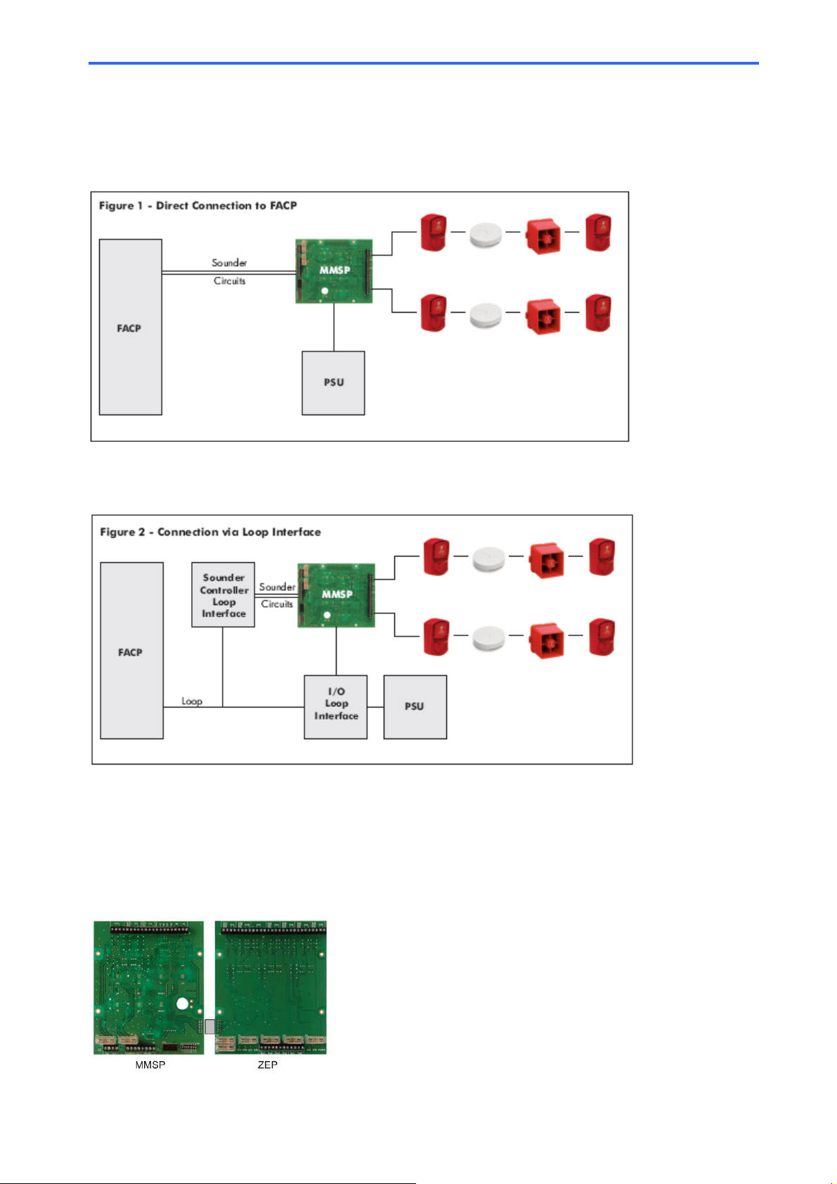
The Fire-Cryer® Plus Multi Message Switching PCB
Part Ref: MMSP
Features:
¾2 Sounder Circuits rated @ 2A per circuit
¾7 messages
¾Fully monitored sounder circuits with two additional fully monitored inputs for panic or incident alarm
¾All messages synchronised within a 4 zone (8 Sounder Circuits) system (when used with the Vimpex Zone
Extension PCB Part Ref. ZEP)
¾Fully expandable with limitless zones with added MMSP and ZEP
¾Diagnostic LEDs
¾Optional integrated keypad and enable key switch for message selection
¾Optional Metal enclosure designed around the Kentec range of panels. Can be delivered prewired with or
without a PSU
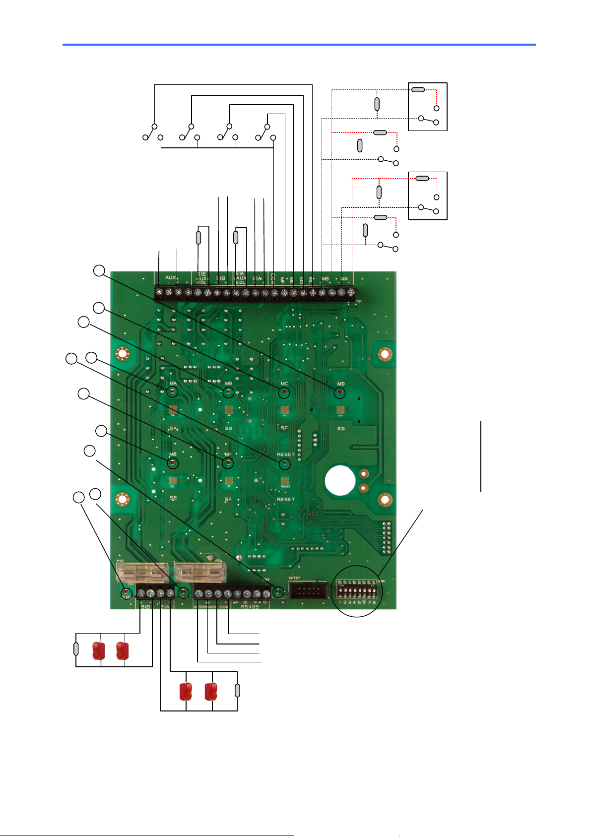
LED Indicators (Refer to Figure 3)
Power healthy and MMSP powered illuminates the GREEN LED cunder ‘Reset’.
Processor healthy will be indicated by a ‘blinking’ GREEN LED dmarked ‘PROC’
Transmission of a message illuminates the RED LEDs efon both sounder circuits (S1A and S1B)
Activation of auxiliary messages (MA through to MF) will illuminate the corresponding RED LEDs g, h, i, j, k
If the input to S1A or S1B is energised and LED eor fis not illuminated, then the fuses should be checked. If LED
eor fis illuminated and the incorrect message is being broadcast this may indicate excessive volt drop (<20VDC)
Terminals (Refer to Figure 3)
AUX - - + + 24VDC Input
S1A / S1B AUX EOL. The sounder circuits S1A and S1B are provided with auxiliary EOL terminals. Fit the panel
manufacturer’s recommended EOL Resistor here. This suppresses fault signals when an auxiliary message is
broadcast.
MA, MB, MC, MD, ME and MF These are 6 additional inputs. MA and MB are fully monitored inputs requiring a 3K3Ω
EOL termination resistor which is supplied. To activate MA or MB, a 470Ωresistor is needed in series with the switch.
The remaining four inputs when linked to COM will trigger the remaining auxiliary messages.
INTERBOARD SYNC This terminal is used to link multiple MMSPs and ensures synchronisation for S1A and S1B
across all MMSPs
Factory Set Options. The following options can be requested when placing the order
Pulsing Input – If the sounder inputs are pulsed 1 second on, 1 second off, this will automatically broadcast a pre
selected message, usually an ALERT or pre-alarm message. FACTORY DEFAULT IS OFF
Auto All Clear Mode – If the ALERT or pre-alarm message is cancelled a pre selected ALL CLEAR message will be
automatically broadcast. The number of repeats of the ALL CLEAR is also set at this time. FACTORY DEFAULT IS OFF
Timeout – This allows a message to be broadcast for a time set by DIL switches 1-4 (see Table 1) to allow for
investigation prior to evacuation. FACTORY DEFAULT IS OFF
Latch Inputs – Any or all inputs MA, MB, MC, MD, ME and MF can be latched. FACTORY DEFAULT IS OFF
Message Termination - Messages can be set to terminate immediately or at end of message. FACTORY DEFAULT IS
END OF MESSAGE
User Options
8-way DIL switch
SW7 and SW8 are used to disable MA and/or MB indicators respectively on the keypad.
SW1-4 are used to set the time in ‘timeout mode’ as a field adjustable function. (See Table 1)
SW5 and SW6 have no function at present.
www.acornfiresecurity.com

Figure 3
EOL
EOL
To / From additional
MMSP
To / From additional
MMSP
EOL
EOL
Fire Panel
Sounder Outputs
BA
AUX 24V DC Supply
(Note: Join AUX
24VDC -(ve)
to -(ve) of Fire Panel)
MC
ME
MF
MD
470R
3K3
NO NC
470R
3K3
470R
3K3
3K3
470R
NO NC
MCP MCP
Fire Panel
Relay
Fire Panel
Relay
LED 4
LED 3
LED 1
LED 2
LED 10
LED 9
LED 8 LED 7
LED 6 LED 5
R1: 470ΩResistor
R2: 3K3ΩResistor (Supplied)
R1
R1 R1
R1
R2 R2
R2
R2
8-Way DIL Switch
SW7 & SW8are used to disable MAand/or MB indicators respectively
on the keypad.
SW1-4 are used to set the time in 'timeout mode' as a field adjustable
function–Timeout Mode is a factory set option. See Table 1.
SW5 & SW6 are not used
www.acornfiresecurity.com

The Fire-Cryer Plus® Zone Extension PCB
Part Ref: ZEP
Features:
¾6 Sounder Circuits rated and independently fused @ 2A per circuit
¾Adds 3 zones or 6 Sounder circuits to an MMSP
¾All messages synchronised within a 4 zone (8 Sounder Circuits) system (when used with the Vimpex Multi-
Message Switching PCB Part Ref. MMSP)
¾Fully expandable with limitless zones with added MMSP and ZEP
¾Diagnostic LEDs
¾Optional Metal enclosure designed around the Kentec range of panels. Can be delivered prewired with or
without a PSU
LED Indicators (Please refer to Figure 4)
Power healthy and ZEP powered illuminates the GREEN LED c‘POWER’
Transmission of a message illuminates the RED LEDs d, e, f, g, h, ion all sounder circuits.
Terminals (Please refer to Figure 4)
Ribbon Cable Link to MMSP
S2A, S2B, S3A, S3B, S4A and S4B – Sounder inputs from Control Panel
S2A, S2B, S3A, S3B, S4A and S4B AUX EOL. The sounder circuits S2A, S2B, S3A, S3B, S4A and S4B are provided
with auxiliary EOL terminals. Fit the panel manufacturer’s recommended EOL Resistor here. This suppresses fault
signals when an auxiliary message is broadcast.
S2A, S2B, S3A, S3B, S4A and S4B – Sounder Outputs from ZEP
AUX ++ --
24VDC - Input (Max load of 12A requires Min. 1.5mm CSA up to 2 metres in length). Negative –(ve) of AUX PSU
MUST be connected to Negative –(ve) of Control Panel and Negative –(ve) of AUX PSU if used with MMSP.
www.acornfiresecurity.com

Figure 4
Fire Panel
Sounder Outputs
AB
Fire Panel
Sounder Outputs
AB
Fire Panel
Sounder Outputs
AB
AUX 24V DC Supply
(Note: Join Aux -(ve) of
PSU to Fire Panel -(ve)
Ribbon cable
link to MMSP
EOL
Repeat for circuits S4B, S2A, S2B, S3A and S3B
LED 1LED 4
LED 5
LED 7
LED 6
LED 2
LED 3
EOL
EOL
EOL
EOL
EOL
EOL
www.acornfiresecurity.com
This manual suits for next models
5
Other Vimpex Marine Equipment manuals
Popular Marine Equipment manuals by other brands

Cellofoam
Cellofoam PERMAPORT XPRESS Assembly, installation and maintenance instructions

Lowrance
Lowrance LRG-1500A Installation and operation manual

Garmin
Garmin GSD 22 installation instructions

Simrad
Simrad EY500 instruction manual

locmarine
locmarine LTE-10 installation guide

Qlightec
Qlightec QAP100BZ user manual