Moog Tritech Micron Gemini User manual

Micron Gemini
0729-SOM-00004-01 Page 1 of 46
Micron Gemini
Product Manual
0729-SOM-00004-01

Micron Gemini
0729-SOM-00004-01 Page 2 of 46
© Tritech International Ltd
The copyright in this document is the property of Tritech International Ltd. The document is supplied by
Tritech International Ltd on the understanding that it may not be copied, used, or disclosed to others
except as authorised in writing by Tritech International Ltd.
Tritech International Ltd reserves the right to change, modify and update designs and specifications as
part of their ongoing product development programme. All product names are trademarks of their
respective companies.
Open Source License Statement: This product includes software code developed by third parties,
including software code subject to the GNU General Public License Version 2 ("GPLv2"). We will
provide upon request the applicable GPL source code files via CD-ROM or similar storage medium for
a nominal cost to cover shipping and media charges as allowed under the GPL. This offer is valid for a
3 year period from first manufacture of this product.
General Public License ("GPLv2") Inquiries: Please direct all GPL inquiries to the following address:
Tritech International Ltd
Peregrine Road
Westhill Business Park
Westhill, Aberdeenshire
AB32 6JL, UK

Micron Gemini
0729-SOM-00004-01 Page 3 of 46
Table of Contents
Help & Support...................................................................................................................... 4
Warning Symbols.................................................................................................................. 5
Introduction ........................................................................................................................... 6
Technical Specifications ...................................................................................................... 7
Sonar Variants..................................................................................................................... 9
Getting started .................................................................................................................... 10
Serial System Test Kit ....................................................................................................... 11
Ethernet System Test Kit................................................................................................... 12
Assembling the Serial System........................................................................................... 13
Assembling the Ethernet System ...................................................................................... 15
Installation ........................................................................................................................... 16
Communications Protocols................................................................................................ 16
Serial.............................................................................................................................. 16
Ethernet ......................................................................................................................... 17
Electrical Installation.......................................................................................................... 18
Connector Maintenance Guidelines............................................................................... 18
Ground Fault Monitoring ................................................................................................ 18
Power............................................................................................................................. 18
Hardware Installation......................................................................................................... 19
Installing the Micron Gemini using Tritech Mounts ........................................................ 21
Operation ............................................................................................................................. 28
Maintenance ........................................................................................................................ 29
General guidance .............................................................................................................. 29
After Use........................................................................................................................ 29
Equipment Storage ........................................................................................................ 29
Sacrificial Anode Information............................................................................................. 30
Pressure Sensor Maintenance (300m only) ...................................................................... 31
Troubleshooting.................................................................................................................. 32
Appendix A - Connector Details ........................................................................................ 35
Tritech Micron ................................................................................................................ 36
Impulse Titan™.............................................................................................................. 38
Souriau UTS6JC124S – S09126 ................................................................................... 40
USB to Serial Adapter Cable Options............................................................................ 40
Appendix B - Mounting Bracket Details............................................................................ 41
Sonar Mounting Bracket - S11708................................................................................. 41
Mounting Bracket 10° Adaptor - S11709 ....................................................................... 41
Pole Mount Adapter - S11790 ....................................................................................... 42
Clamp Mount Adapter - S11846 .................................................................................... 42
Appendix C - Setting the computer IP address in Windows® XP .................................. 43
Appendix D - Setting the computer IP address in Windows® 7 or Windows® 10 ........ 45
Micron Gemini
0729-SOM-00004-01 Page 4 of 46
Help & Support
First please read this manual thoroughly (particularly the Troubleshooting section, if present).
If a warranty is applicable, further details can be found in the Warranty Statement, 0080- STF-
00139, available upon request.
Tritech International Ltd can be contacted as follows:
Mail Tritech International Ltd
Peregrine Road
Westhill Business Park
Westhill, Aberdeenshire
AB32 6JL, UK
Telephone +44(0)1224 744 111
Email [email protected]
Website www.moog.com/tritech
Prior to contacting Tritech International Ltd please ensure that the following is available:
1. The Serial Numbers of the product and any Tritech International Ltd equipment
connected directly or indirectly to it
2. Software or firmware revision numbers
3. A clear fault description
4. Details of any remedial action implemented
Contamination
If the product has been used in a contaminated or hazardous environment,
you must de-contaminate the product and report any hazards prior to
returning the unit for repair. Under no circumstances should a product be
returned that is contaminated with radioactive material.
The name of the organisation which purchased the system is held on record at Tritech
International Ltd and details of new software or hardware packages will be announced at
regular intervals. This manual may not detail every aspect of operation and for the latest
revision of the manual please refer to www.moog.com/tritech
Tritech International Ltd can only undertake to provide software support of systems loaded
with the software in accordance with the instructions given in this manual. It is the customer's
responsibility to ensure the compatibility of any other package they choose to use.
Micron Gemini
0729-SOM-00004-01 Page 5 of 46
Warning Symbols
Throughout this manual the following symbols may be used where applicable to denote any
particular hazards or areas which should be given special attention:
Note
This symbol highlights anything which would be of particular interest to the
reader or provides extra information outside of the current topic.
Important
When this is shown there is potential to cause harm to the device due to
static discharge. The components should not be handled without
appropriate protection to prevent such a discharge occurring.
Caution
This highlights areas where extra care is needed to ensure that certain
delicate components are not damaged.
Warning
DANGER OF INJURY TO SELF OR OTHERS
Where this symbol is present there is a serious risk of injury or loss of life.
Care should be taken to follow the instructions correctly and also conduct a
separate Risk Assessment prior to commencing work

Micron Gemini
0729-SOM-00004-01 Page 6 of 46
Introduction
The Micron Gemini takes Tritech’s Gemini Multibeam technology and fits it in a form factor
that fits with the Tritech Micron family to create the world’s smallest Multibeam imaging sonar.
Having a 90° horizontal field of view and 50m end range, with an update rate up to 20Hz and
incredibly compact dimensions the Micron Gemini can be used in applications where size is
critical. This makes the Micron Gemini ideally suited to micro ROV/AUV’s, as well as
applications where space is restricted or weight is critical, for example on diver helmets and
pole mounted applications for Search and Recovery (SAR) operations.
The Micron Gemini communicates with Tritech’s next generation integrated software suite
Genesis using Ethernet or Tritech’s advanced Serial Multibeam Protocol (TSMP). The
auxiliary port on the sonar allows for the daisy chaining of sensors including the Micron USBL
Modem and Micron Echo Sounder. Advanced adaptive processing ensures that the most
detailed image possible is generated regardless of range. This includes automatic switching
between Compressed High Intensity Radar Pulse (CHIRP) and Continuous Wave (CW)
modes of operation to maximize image definition.
Tritech’s next generation integrated software suite Genesis is supplied with the Micron Gemini
and is available from the Tritech website, supporting all Tritech’s sensors. There is also a
Windows® and Linux Software Development Kit (SDK) for the sonar to allow users to fully
integrate the Micron Gemini into a customised system.

Micron Gemini
0729-SOM-00004-01 Page 7 of 46
Technical Specifications
Drawing shown with 750m Micron Gemini fitted with an Impulse MKS(W)-3L10 connector.
All dimensions are in mm, not to scale.
Acoustic Specifications
Operating frequency 720 kHz
Angular resolution 2.34° acoustic, 0.7° effective
Range 0.2 m to 50 m
Number of Beams 128
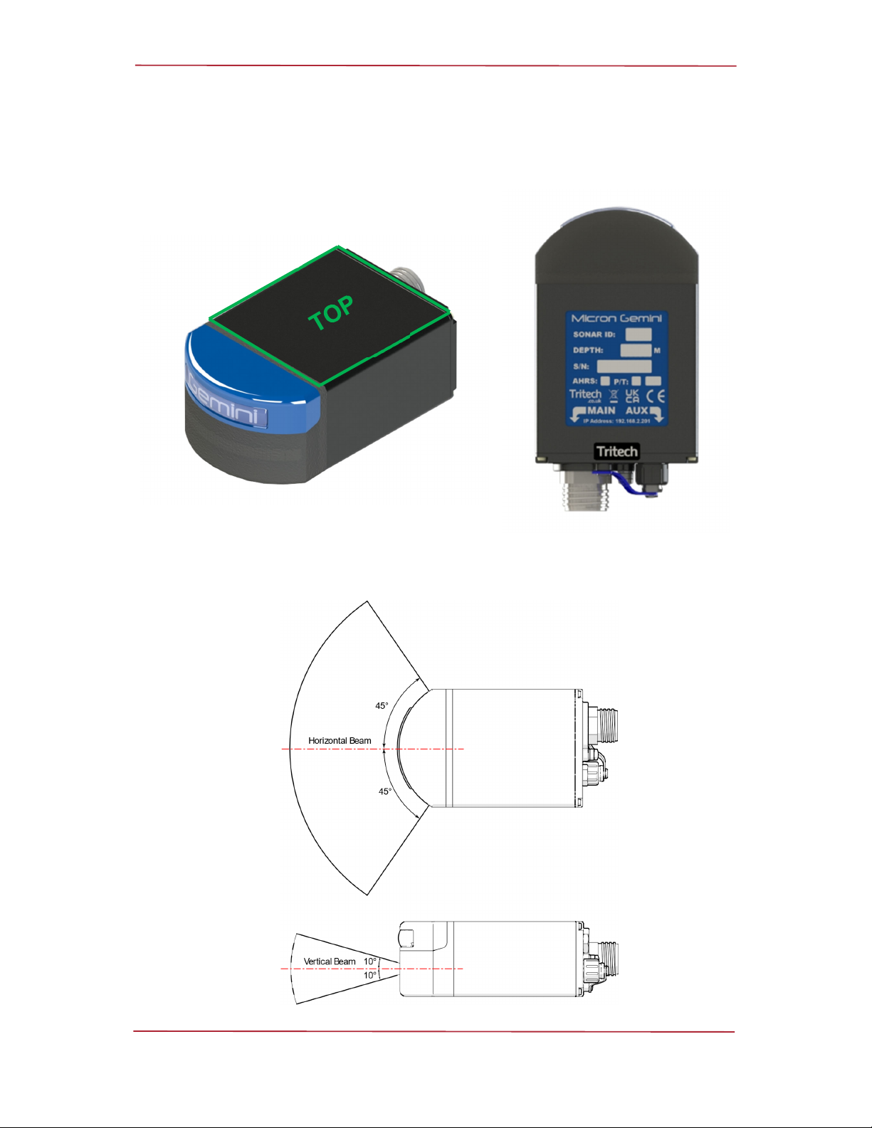
Horizontal Beam Width 90°
Vertical Beam Width 20° (±10° about horizontal axis)
Update rate (typical) 3 to 20 Hz (range dependant)
Range Resolution 8 mm (range dependant)
Mode of operation Constant Wave (CW) or Chirp
Speed of sound Set via surface interface software
Integrated Sensor Specifications (300m only)
Depth Accuracy ± 2 m
Temperature Accuracy ± 2.0 °C

Micron Gemini
0729-SOM-00004-01 Page 8 of 46
Interface
Supply voltage 12 to 48 VDC
Power requirement 5 W-8 W (range dependant)1
Main port protocol Ethernet (100Base-T) and / or Serial (RS232 or RS485)
Auxiliary port protocol Auxiliary port protocol Serial (RS232 or RS485)
Connector type Main: Impulse Titan™ or Tritech Micron
Aux: Tritech Micron
Physical Specifications
Depth Rating 300 m or 750 m
Weight in air 0.429 kg
Weight in water 0.240 kg
Temperature rating -10 to 35 °C, (Storage -20 to 50 °C)
1 The power consumption figures listed are average readings which include transients up to 29 W

Micron Gemini
0729-SOM-00004-01 Page 9 of 46
Sonar Variants
The following shows the 3 different connector types, the communication protocols associated
with them and depth ratings.
Tritech MICRON Connecto
r
Communications Depth Rating
300m 750m
RS232/RS485
S12683 S12686
Impulse Titan™
Communications Depth Rating
300m 750m
Impulse Titan™
MKS(W)-307
Ethernet ONLY S12682 S12685
Impulse Titan™
MKS(W)-3L10
RS485
Or
Ethernet
S12681 S12684
For pin out connector information, please see “Appendix A”

Micron Gemini
0729-SOM-00004-01 Page 10 of 46
Getting started
The following instructions are to help the user connect the system together for the first time
and be able to successfully power on the unit. In order to prepare the system and test its
functionality before mounting to a vehicle, the Micron Gemini requires either an Ethernet or
Serial test kit (depending on user requirement).
If seeking support from Tritech, reference may be made to bench testing the unit on a short
test cable
An example Micron Gemini test setup

Micron Gemini
0729-SOM-00004-01 Page 11 of 46
Serial System Test Kit
The serial system test kit has different part numbers. This reflects the different mating tails
required for the connector fitted to the Micron Gemini purchased. Please reference the serial
number of the Micron Gemini and connector variant when in conversation with Tritech. The
following serial system tests kits are available:
S11796−KIT1−Tritech Micron test kit
S11792−KIT2−Impulse Titan™ 3L10 test kit
In general, the serial system test kits includes the following parts:
S11670 Gemini Power/Ethernet/Serial Break-out Assembly
A Gemini Power/Ethernet/Serial Break-out
Assembly, enabling connection via a Serial to USB
connection - for use in RS232/RS485 mode
S11346 Gemini imaging sonar power supply unit
A power supply unit
(Country specific mains plug -specify at point of sale)
10m serial test cable
Souriau to Impulse Titan™ 3L10
or
Tritech Micron

Micron Gemini
0729-SOM-00004-01 Page 12 of 46
Ethernet System Test Kit
The Ethernet system test kit has different part numbers. This reflects the different mating tails
required for the connector fitted to the Micron Gemini purchased. Please reference the serial
number of the Micron Gemini and connector variant when in conversation with Tritech. The
following serial system tests kits are available:
S11624−KIT2−Impulse Titan™ 307 test kit
S11792−KIT2−Impulse Titan™ 3L10 test kit
In general, the Ethernet system test kits includes the following parts:
S11561 Gemini Power/Ethernet Break-out Assembly
A Gemini Power/Ethernet Break-out Assembly,
enabling an Ethernet connection via an RJ45 plug
S11346 Gemini imaging sonar power supply unit
A power supply unit
(Country specific mains plug -specify at point of sale)
10m serial test cable
Souriau to Impulse Titan™ 3L10
or
Souriau to Impulse Titan™ 307
Micron Gemini
0729-SOM-00004-01 Page 13 of 46
Assembling the Serial System
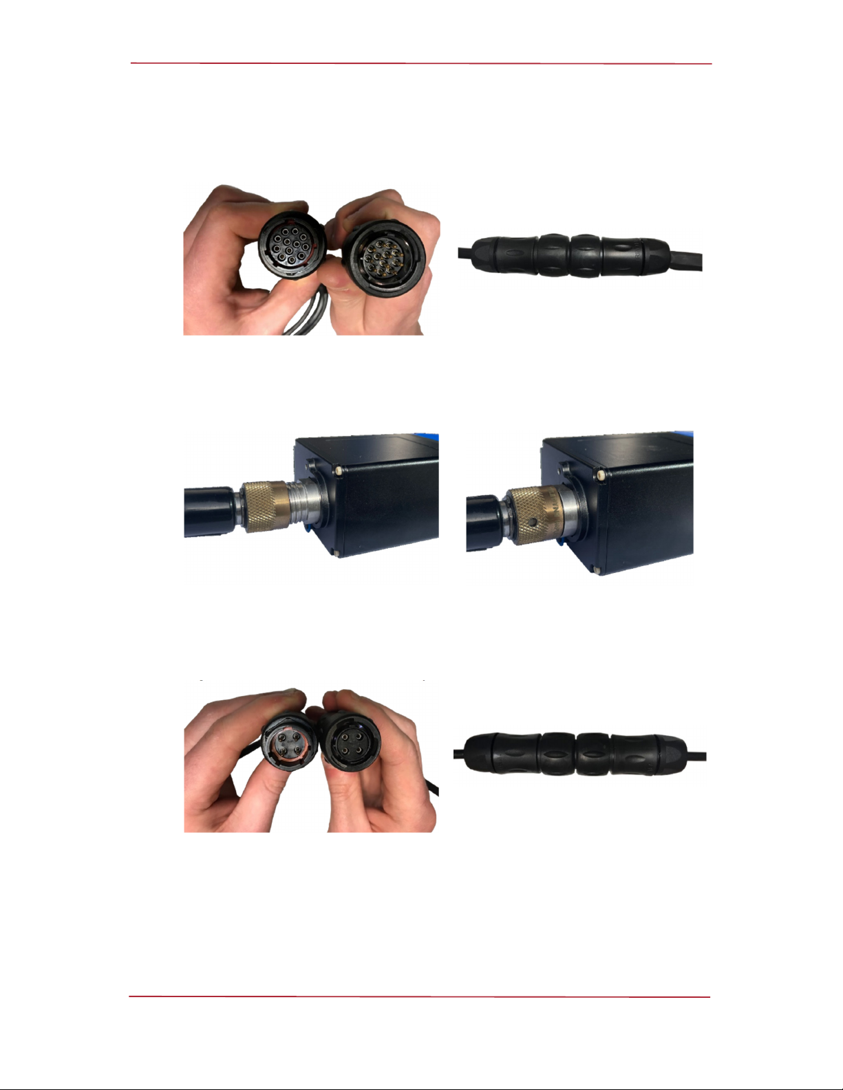
Step 1
Connect the breakout assembly to the 10 metre serial test cable, making sure to
properl
y
ali
g
n the Souriau connector and its ke
y
wa
y
.
Female connector of the breakout assembly
and male connector of the test cable
A correctly mated Souriau communications
cable
Step 2
Plug the connector end of the 10 metre serial cable into the Micron Gemini sonar,
following the connection procedure for the appropriate connector.
An Impulse™ cable ready to be mated to the
connector
A correctly mated Impulse™ cable
Step 3
Connect the power supply unit to the breakout assembly, making sure to properly
ali
g
n the Souriau connector and its ke
y
wa
y
.
Female connector of the power supply unit
and male connector of the breakout
assembly
A correctly mated power cable
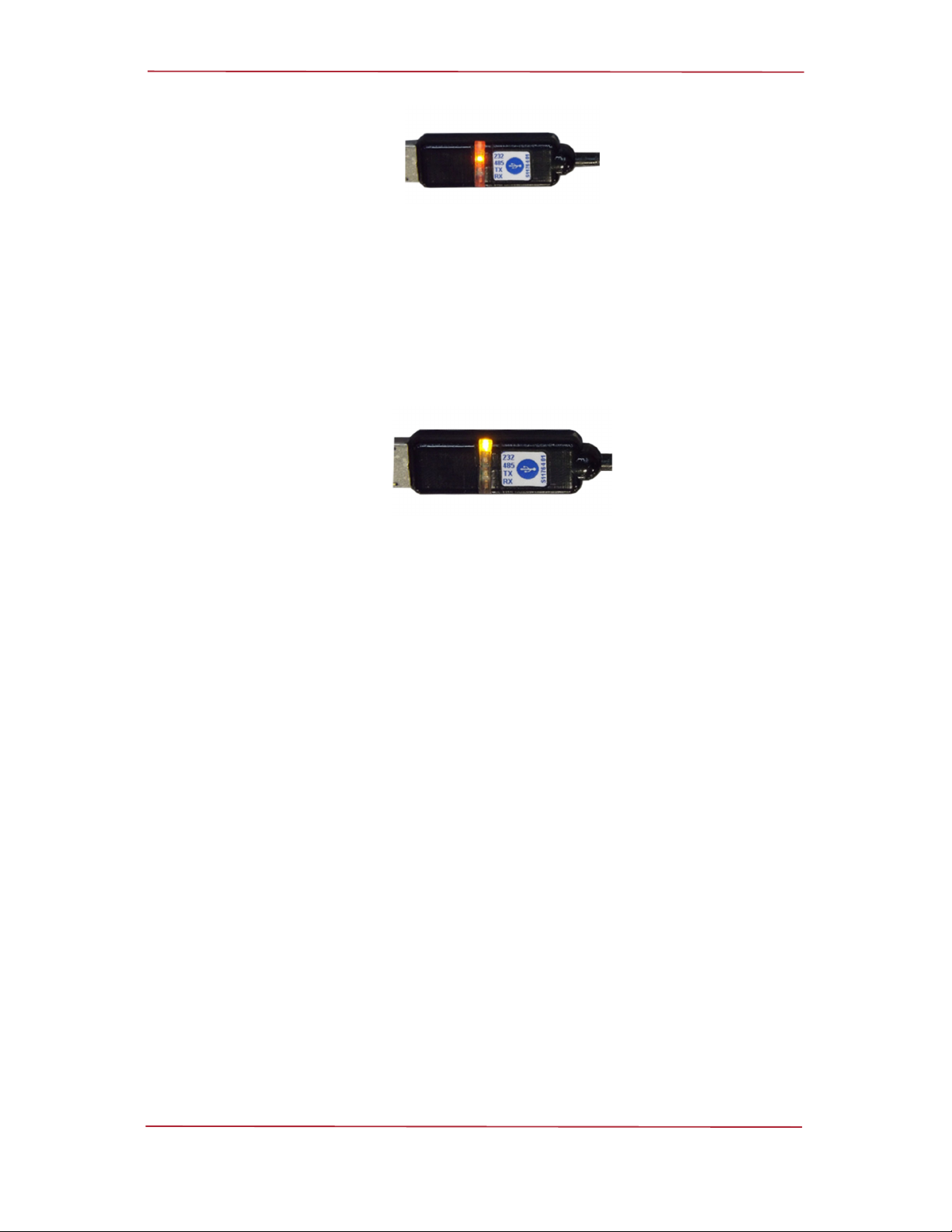
Step 4
Plug the USB connector on the serial breakout assembly into your computer, once
this is done an orange LED will be dimly lit, indicating the system is ready to establish
communications
Micron Gemini
0729-SOM-00004-01 Page 14 of 46
A USB to serial converter indicating that it is establishing communications
Step 5
Once the system has established communication, the LED on the USB connector
will be fully illuminated. The system is now ready to operate with the software, green
LED’s indicate the transmission and reception of data.
For more details of configuring the sonar parameters, please see the Genesis
software manual and quick start guides available from the Tritech website see “Help
& Support.”
A USB to serial converter indicating that has established communications

Micron Gemini
0729-SOM-00004-01 Page 15 of 46
Assembling the Ethernet System
The assembly of the Ethernet system is similar to the process detailed in the Serial system
Step 1
Connect the Breakout assembly to the 10m Ethernet test cable, taking care to
properly align the Souriau connector and its keyway.
Step 2
The connector on the Gemini and the Power Supply cable should be connected,
similar to the instructions given for the Serial System setup (see ”Assembling the
Serial System”).
Step 3
The Ethernet system requires the RJ45 connector plugged into your computer
instead of the USB device.
If using the system for the first time or after installing new software. See “Setting the
computer IP address in Windows® XP” or “D - Setting the computer IP address in
Windows® 7 or Windows® 10” for information on setting up your computers Ethernet
network port.

Micron Gemini
0729-SOM-00004-01 Page 16 of 46
Installation
Communications Protocols
This section details communication information that should be taken into consideration prior
to installation.
Serial
In order to achieve the maximum performance from the serial link it is recommended that the
Tritech USB adapter is used. The Tritech USB allows Genesis and the Gemini to automatically
negotiate to the maximum permissible baud rate for the line. The higher the baud rate the
greater the bandwidth, resulting in an increase in the image update and quality.
The serial speeds available through the Tritech USB adapter are:
115200
230400
460800
921600
2Mbps
3Mbps
4Mbps
Note
When using the Tritech USB adapter, Genesis will automatically detect the
USB hardware plugged into the PC and populate Genesis with the Micron
Gemini information.
RS232
The maximum permissible speed for RS232 is 921600 baud. This will only be achieved if the
cabling is of a sufficient quality and below a certain length.
The maximum length of standard Tritech Micron cable that will support 921600 baud is 1 m.
This means that you will not achieve the maximum RS232 baud rate with the supplied 10m
Micron RS232 test cable.

Micron Gemini
0729-SOM-00004-01 Page 17 of 46
RS485
This is the preferred serial communications protocol. It is recommended that the minimum
speed 921600 baud be used for best overall performance.
Autocomms
The Tritech USB adapter supports auto negotiation of baud rate and communications protocol.
When it starts it always defaults to RS485. If RS232 is required, then you will need to left
mouse click on the ID number of the Micron Gemini and select RS232 from the dropdown
within the General tab.
This will only be an issue on links that do not allow RS485 communication, i.e. a fibre optic
multiplexer
Serial Wiring
For wiring of the DE-9 connector please see “USB to Serial Adapter Cable Options”
Ethernet
The Ethernet adapter on the host PC must be in the same IP address range as the Gemini
being attached. Using network comms allows multiple Geminis to be integrated using standard
networking equipment.
Things to note:
The Micron Gemini works on 100BASE−TX link.
It is not recommended that you connect the Gemini units through a network hub. It is
recommended that Gemini sonar units are connected using a network switch.
Note
A network hub broadcast to all its ports and thus shares its bandwidth with
each of the ports. If multiple devices are connected then the bandwidth
allocation will be shared between devices, and so the bandwidth per device
will drop. This will negatively affect the performance of the network.
A network switch keeps records of the MAC addresses of the devices
connected so when a frame of data is received the data is sent to the
appropriate port rather than broadcast. This means that each port on a
network switch will have the maximum amount of bandwidth.
Check your antivirus situation. Firewalls will see the data from the Gemini and may
stop the broadcast message. Occasionally a firewall will allow the broadcast message
but will stop the high data rate from imaging believing it to be a denial-of-service attack.

Micron Gemini
0729-SOM-00004-01 Page 18 of 46
Electrical Installation
For electrical installation please see the connector pinouts in “Appendix A”
For the Micron connector there is a 1 metre test cable available which is terminated to a D-
Type Sub-Miniature connector, see “Micron Test Cable - S11640 XXm”.
Connector Maintenance Guidelines
Mating surfaces should be lubricated with 3M Silicone Spray or equivalent, DO NOT GREASE.
Connectors must be lubricated on a regular basis. Clean plugs and receptacles with soap and
fresh water.
Important
When attaching a connector make sure that both connector and socket are
completely dry. Any water trapped in the connection could result in an
electrical short.
Unused connectors must have a blanking cap fitted prior to immersing in
water. Failure to do this will cause permanent damage.
If using alcohol or IPA to clean out the connector take care that it does not
come into contact with any other part of the sonar.
Ground Fault Monitoring
The power supply within the Gemini includes an electrically isolated DC-DC converter
frontend. There is a small capacitive connection between the isolated ground and the sonar
chassis which should not noticeably affect any impressed current Ground Fault Indicator (GFI)
equipment.
Power
Important
Never try to make the Gemini work down a long cable by increasing the
PSU output voltage above 48V DC.
Important
Power should only be supplied to the Gemini through the MAIN port. The
AUX port power is supplied via pass through from the MAIN port.
Warning
The Gemini PSU that is supplied with the Gemini system is intended for
INDOOR USE ONLY and should not be placed in a position where it could
get wet.
Micron Gemini
0729-SOM-00004-01 Page 19 of 46
Hardware Installation
To correctly mount the Micron Gemini, the blue Gemini logo/mould should be at the top, and
the product label at the bottom.
The transmit and receive elements are arranged such that they are angled at 0° about the
horizontal axis which should be considered when mounting the sonar.
BOTTOM

Micron Gemini
0729-SOM-00004-01 Page 20 of 46
Any metallic clamps should be electrically insulated from the sonar body by either rubber or
plastic strips or mounting brackets of at least 3 mm thickness and extending at least 3 mm
beyond the clamp boundary to reduce any galvanic corrosion effect. Non-metallic clamps are
preferable; if metallic clamps are used (especially if they are different in composition to the
material used by the sonar) they should be painted or lacquered with at least two or three
coatings.
Note
Before connecting the Micron Gemini, it is recommended that the subsea
cable connectors are examined for any damage, free of debris, clean and
dry.
Caution
The outer case of the Micron Gemini is made of anodized aluminium. When
deploying the sonar, direct contact with copper alloys such as brass or
bronze should be avoided.
Table of contents
Other Moog Marine Equipment manuals


