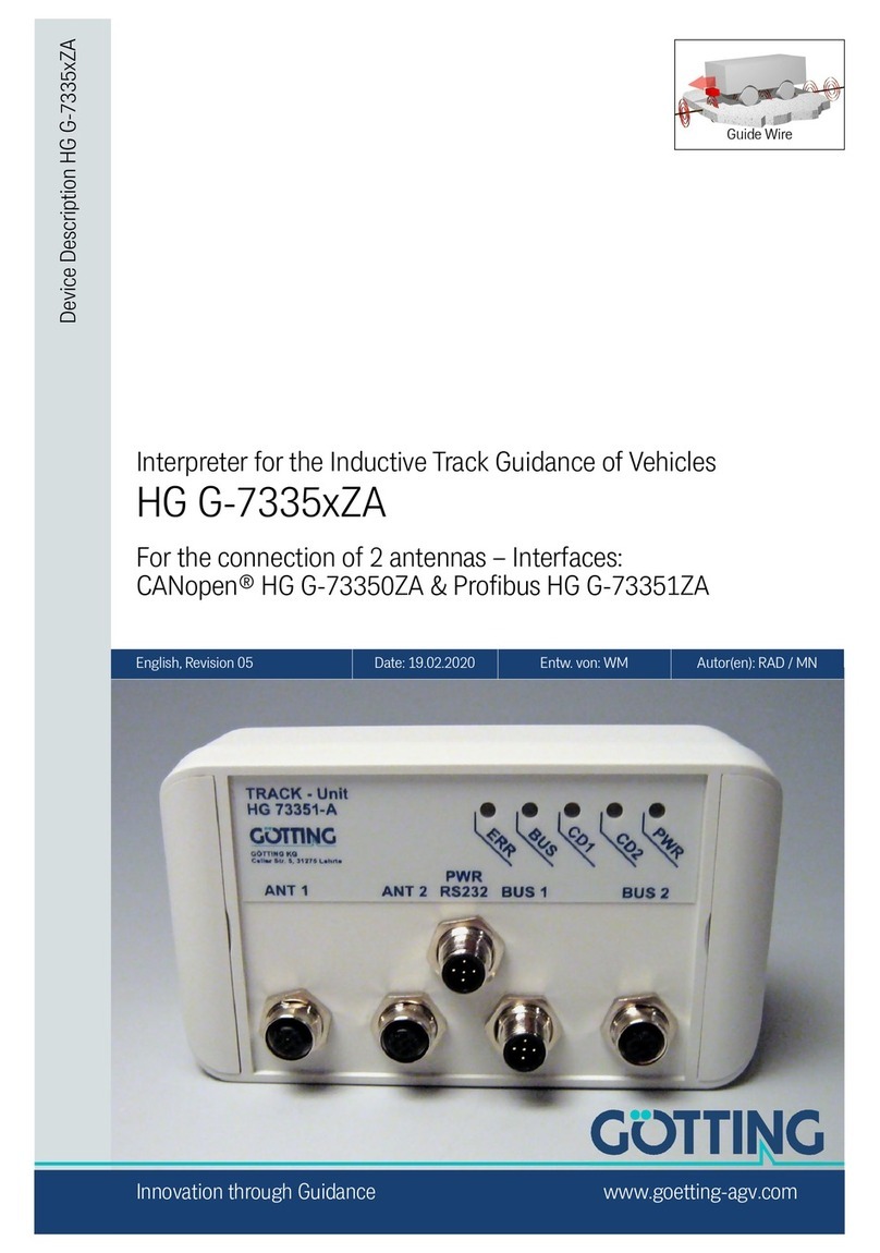
Gotting HG 73350 Operating and installation instructions

Content G_73350ZA
English, Revision 01, Date: 14.04.2009 2
Content
1 Essential Information for Reading this Manual....................4
2 Introduction.......................................................................5
3 Mounting...........................................................................6
3.1 Casing.................................................................................... 6
3.2 Connecters ............................................................................. 6
3.2.1 Aerial socket of the interpreter ....................................................... 6
3.2.2 CAN bus........................................................................................ 7
3.2.3 Power supply and serial interface................................................... 7
4 Commissioning..................................................................8
5 Hardware ..........................................................................9
5.1 Monitoring .............................................................................. 9
5.2 Presetting............................................................................... 9
5.3 Processing the signal.............................................................. 9
5.4 The Control LED ................................................................... 10
6 Software .........................................................................11
6.1 Monitor program ................................................................... 11
6.1.1 Main menu .................................................................................. 11
6.1.2 Antenna menu ............................................................................. 12
6.1.3 CAN menu................................................................................... 14
6.2 Changing the surrounding ..................................................... 16
6.3 Updating the software ........................................................... 16
7 CAN Interface .................................................................18
7.1 Description of the process data objects (PDOs) ..................... 18
7.1.1 Transmission objects ................................................................... 18
7.1.2 Receiving objects ........................................................................ 19
7.2 Heartbeat ............................................................................. 20
7.3 Writing on service data objects (SDOs) ................................. 20
7.4 Object directory .................................................................... 21
7.4.1 Communication specific entries.................................................... 21
7.4.2 Manufacturer entries.................................................................... 23
7.4.3 Standard device profile ................................................................ 24
7.4.4 CANopen Object Dictionary ......................................................... 25
7.4.4.1 Device Type ........................................................................... 25
7.4.4.2 Error Register ......................................................................... 25
7.4.4.3 COB-ID SYNC message.......................................................... 25

Content G_73350ZA
English, Revision 01, Date: 14.04.2009 3
7.4.4.4 Device Name .......................................................................... 25
7.4.4.5 Hardware Version ................................................................... 26
7.4.4.6 Software Version .................................................................... 26
7.4.4.7 Save Parameter...................................................................... 26
7.4.4.8 Restore Default Parameter...................................................... 26
7.4.4.9 Producer Heartbeat Time ........................................................ 27
7.4.4.10 Identity Object ........................................................................ 27
7.4.4.11 Receive PDO Parameter ......................................................... 27
7.4.4.12 Mapping RPDO_1 ................................................................... 28
7.4.4.13 Transmit PDO_1 Parameter .................................................... 28
7.4.4.14 Transmit PDO_2 Parameter .................................................... 29
7.4.4.15 Mapping TxPDO_1.................................................................. 29
7.4.4.16 Mapping TxPDO_2.................................................................. 30
7.4.4.17 Manufacture Parameter - parameters of the antenna ............... 31
7.4.4.18 Manufacture parameter - calibration of the antenna ................. 32
7.4.4.19 Manufacture parameter - node parameter................................ 33
7.4.4.20 8 Bit Digital Input (transmitted in TxPDO 1) ............................. 34
7.4.4.21 16 Bit Analog Inputs (transmitted in TxPDO 1 und TxPDO 2) ... 34
8 Troubleshooting ..............................................................35
9 Technical data.................................................................36
10 Appendix.........................................................................37
A Block diagram .................................................................................. 37
B Diagrams.......................................................................................... 38
C Electronic Data Sheet (EDS file) ...................................................... 41
11 List of figures ..................................................................42
12 List of tables ...................................................................43
13 Copyright and Terms of Liability ......................................45
13.1 Copyright.............................................................................. 45
13.2 Exclusion of Liability ............................................................. 45
13.3 Trade Marks and Company Names........................................ 45

Essential Information for Reading this Manual G-76341-A
English, Revision 01, Date: 14.04.2009 4
1 Essential Information for Reading this Manual
In documentations of Götting KG the following symbols and assignments were used
at the time of printing this manual:
Security advices have the following symbols, depending on the emphasis and the
degree of exposure:
NOTE!
ATTENTION!
CAUTION!
WARNING!
Continuative information and tips are identified as follows:
Tip!
Program texts and variables are highlighted by using the font ’Courier’.
Whenever input of key combinations is required for the operation of programms,
the corresponding Keys are highlighted (in Götting KG programs it is usually
possible to use small and capitalized characters equally).
Sections, figures and tables are automatically numbered consecutively through-
out the entire document. In addition, each document has an index listed behind
the front page, including pages and - whenever the document has more than 10
pages - following the actual system description a figure and table index in the
back. In certain cases (for long and/or complicated documents) a subject index is
added.
Each document provides a table block with metainformation on the front page,
indicating the system designer, auther, revision and date of issue. In addition, the
information regarding revision and date of issue are included within the footer of
each page, enabling the exact allocation of the information with a date and certain
a system revision.
Online-Version (PDF) and printed manual are generated from the same source.
Due to the consistent use of Adobe FrameMaker for the generation of documenta-
tion, all directory entries (including page numbers and subject index) and cross
references in the PDF file can be clicked on with the mouse and will lead to the
corresponding linked contents.

Introduction G_73350ZA
English, Revision 01, Date: 14.04.2009 5
2 Introduction
The described interpreter allows to connect two tracking antennas to one device.
The interpreter contains two identical channels with an independent setting of the filter
frequency. The output of the data is realized with a CAN bus. A CAN open protocol
(device profile DS 401) is implemented.
The parametrization can be carried out by a terminal programm (e.g. Hyperterm) us-
ing the serial interface or the SDOs of the CAN open protocol.
This documentation was written for hardware version 73350ZA2 and software version
73350A01.14 (or higher).
Components
At the time this manual was printed, the interpreter can be combined with the following
antennas:
-G 19200ZC
-G 19200YC
-G 19210ZA
Technical informations in PDF format about these antennas can be found on our web-
site http://www.goetting.de/en/download/start.html

Mounting G_73350ZA
English, Revision 01, Date: 14.04.2009 6
3 Mounting
3.1 Casing
Figure 1 Casing antenna HG 73350
3.2 Connecters
All connecters are A-coded M12 panel plugs/jacks.
3.2.1 Aerial socket of the interpreter
The antennas and the corresponding 4-pin M12 panel jack are connected with an one-
to-one cable. The two panel jacks are shown in Figure 1, named ANT1 and ANT2. They
are allocated as follows:
It does not matter whether one or two antennas are connected. When using only one
antenna, ANT1 or ANT2 can be chosen. The displaying of CD1/CD2 on the front panel
( see „Postion of the LEDs“ on page 10.) refers to the corresponding antenna input.
The input voltage of ANT1 and ANT2 are processed internally as US1/UD1 or US2/
UD2.
Pin Signal
1+24 V
2GND
3Usum
4Udiff
Table 1 Pin allocation aerial socket
drillhole for mounting

Mounting G_73350ZA
English, Revision 01, Date: 14.04.2009 7
3.2.2 CAN bus
The CAN bus is connected to the device with two 5-pin M12 connecters male/female
(see „Casing antenna HG 73350“ on page 6.). There they can be found as BUS1 and
BUS2, which are allocated as follows:
The connectors of the inputs BUS1/BUS2 are connected in parallel, i.e. there is no in-
put or output. If the interpreter is installed at the end of the bus line, a CAN terminator
has to be installed. Those terminators can be ordered form different manufacturers
and are availbale for most plugs and jacks. The CAN connecters can also be used as
power supply.
ATTENTION! Do not connect +24V to pin 4 or 5!
3.2.3 Power supply and serial interface
Here a 5-pin M12 panel plug is used, in the figure „Casing antenna HG 73350“ on
page 6 this plug called PWR RS232 has the following pin allocation.
This connection serves the power supply. Additionally the serial interface RS 232 can
be used for parametrization.
Pin Signal
1Nc
2+24 V
3GND
4 CAN_H
5 CAN_L
Table 2 Pin allocation CAN bus
Pin Signal Annotation
1+24 V
2Nc
3TxD Serial V.24 data input
4RxD Serial V.24 data output
5GND
Table 3 Pin allocation of power supply and serial interface

Commissioning G_73350ZA
English, Revision 01, Date: 14.04.2009 8
4 Commissioning
After mounting or changing the antennas, a position calibration is recommended. For
further information please see chapter 6.1.2 on page 12 and chapter 7.4.4.18 on page
32. The position calibration has to be carried out for each antenna individually.
NOTE! Only by processing this positioalibration the interpreter is able to
calculate and display the deviation in mm.
For a position calibration the following things are required:
correct positioning of the antenna. I.e. its position has to be the same as the one
set in the interpreter (see also 6.1.2 on page 12 and 7.4.4.17 on page 31)
a guide wire with a rated current (if possible 10 kHz)
The calibration can be started by using the CAN bus or the serial interface. During this
procedure the antenna has to be moved from left to right in a certain area, being two
times mounting height above the wire (see 7.4.4.18 on page 32 and Figure 5 on page
14).

Hardware G_73350ZA
English, Revision 01, Date: 14.04.2009 9
5 Hardware
The casing of the interpreter is made of plastic. All wires etc. can be connected via
M12 connecters on the front panel.The input signals (two per antenna) are amplified,
filtered with an adjustable band filter (frequency input, see Figure 10 on page 38) and
rectified synchronous. Afterwards the direct current runs through a low-pass filter (see
block diagram, Figure 9 on page 37)
5.1 Monitoring
The function of the antennas is controlled: the horizontal component of the field (sum
antenna) is usually controlled by the threshold bits in the system status as a reference.
The vertical component of the field (difference antenna) equals 0 above the middle of
the wire, but a defective difference channel would always cause a deviation of 0.
That is why both channels are controlled by a DC monitoring. In front of the receiving
inductors, 5V are fed into the circuit, which are passed on from amplifier to amplifier
until reaching the interpreter. If this voltage is applied, the status bits DC1-OK respec-
tively DC2-OK are set.
5.2 Presetting
To run the interpreter under different conditions without having to change the circuit
board, the input signals have been scaled: an incoming amplitude of 1 VPP controls
the the sum channel and the difference channel.
An input amplitude of 1 Vss reaches a full range of 75 % between sum channel and the
difference channel.
The CAN baudrate is preset to 125 kbaud, the node ID to 1. The maximal incoming
signal of all data streams having other frequencies is 5 VPP
.
As the parameters of the device (reading height, wire current) can be altered, it is no
problem that the antennas are having different dimensions or being adjusted different-
ly.
1. The interpreter is preset to a frequency of 10 kHz. The threshold for the calcula-
tion of the distances referring itself to 1000 units is preset on input voltage S1
respectively S2. If the sum voltage lies above this value, the corresponding bit is
set in the system status and the corresponding LED CDx lights up. These pre-
settings can be modified using a terminal (for example Hypertem on a PC) or by
using the SDOs of the CAN open protocol (see Table 12 on page 23).
The two channels of the interpreter have the same presettings.
5.3 Processing the signal
The four voltages of the four channels are checked every 500 µs and are added during
a period of 8 ms. Each 10 ms the CAN open protocol is provided with the measured
values. The sum and difference voltages as well as the scaled distances are put out
by the PDOs. To calculate those distances the quotients are formed (current compen-
sated) .

Hardware G_73350ZA
English, Revision 01, Date: 14.04.2009 10
The 16x oversampling and the use of a 10bit A/D converter lead to a value range of
the sum voltage of 16384, of the difference voltage of ±8192.
As in this range the DC offsets of the channels have to be compensated, a range of
about 16000 to ±8000 units is usable.
5.4 The Control LED
On the front panel a group of 5 LEDs can be found.
Figure 2 Postion of the LEDs
-The green LED (PWR) presents the power voltage of the device
-The yellow LEDs (CD1, CD2) show the exceeding of the sum voltage and the set
thresholds for channel 1 and 2.
-The green LED (BUS) flashes after turning on the device. It shows the status of the
device:
-Node stop: LED flashes slowly
-Node reset communication and node preoperational: LED flashes fast
-Node operational: LED is lit continously
-The red LED (ERR) starts to flash as soon as a CAN bus error occurs. Additionally
the red flashing LED displays an error in the set of parameters.

Software G_73350ZA
English, Revision 01, Date: 14.04.2009 11
6 Software
6.1 Monitor program
The terminal (PC with Hyperterm) has to be connected to the interpreter using the
socket in the middle (power supply and serial interface).
The parameters for the serial interface are:
38400,8,e,1,ANSI Terminalemulation.
The monitor will start after pressing M.
6.1.1 Main menu
The following menu appears:
Figure 3 Screenshot: Main menu of the monitor program
The first two lines represent the input.
S1, S2, D1, D2
The values for S1, D1, S2, and D2 are each the sum of the 16 samplings. The range
for the sum voltage is maximal 16 x 1024 = 16384 and for the difference voltage -
16 x 512 until +16 x 511 = -8192 until +8176
X1, X2
X1 and X2 present the calculated values for the collateral deviation of the antennas
above the guide wire in a range from -255 to +255 in mm. The value of the threshold
will be -256 if the corresponding voltages of S1 respectively S2 fall below the set
threshold.
Status
The hexadecimal output of binary coded system statuses in the same format as the
output in the serial telegram or in PDO_1.
S1: 1 D1: -10 S2: 10816 D2: -4403 X1:-256 mm X2: -50 mm Status: 0x40
(1) Select Antenna System 1
(2) Select Antenna System 2
(C)AN Menue
(L)oad Values to EEProm
(O)utput CSV-Data (press 'a' to abort)
(U)pdate Firmware
(S)ervicemenue
(Q)uit
Software Version 73350A01.05 / 15.MAR.2005 Serial Number: 9999999

Software G_73350ZA
English, Revision 01, Date: 14.04.2009 12
Example: If 0xCC is put out, the thresholds in both channels have been
exceeded and both difference channels are operational.
Selecting a menu
-with 1respectively 2the menus for the two antenna systems can be chosen
-Copens the CAN menu
-changed parameters can be saved in the EEProm by pressing L. To confirm
those changes the password 815 has to be entered immediately after.
-to protocol data, the output in CSV (Comma Separated Values) mode can be acti-
vated by pressing O. Then the values of the status line will be displayed sepa-
rated by comma and terminated by CfLF.
Example: 44,0,-15,9627,-3335,-256,50
44,0,-17,9626,-3333,-256,51
In this example the first number “44“ presents the current status of the device (here:
threshold 2 exceeded), then Us1= 0 and Ud1= 17, followed by Us2= 9626 and Ud2=
-3333. The last displayed numbers show the collateral deviations for antenna 1 and
antenna 2. If no wire was detected, -256 is displayed as distance value.
By using the protocol function of Hyperterm the data can be logged. Astops the out-
put.
-with U the firmware can be updated
-the Servicemenu cannot be modified by the user
6.1.2 Antenna menu
In this chapter the sub menu for antenna 1 will be explained. The sub menu for antenna
2 is identical.
0x80 S1 has exceeded the set threshold for channel 1
0x40 S2 has exceeded the set threshold for channel 2
0x20 not connected
0x10 calibration in progress
0x08 DC1_OK (difference channel 1 connected galvanically with interpreter)
0x04 DC2_OK (difference channel 2 connected galvanically with interpreter)
0x02 not connected
0x01 check sum of the two parameters is wrong
Table 4 Meaning of the possible values in the status output

Software G_73350ZA
English, Revision 01, Date: 14.04.2009 13
Figure 4 Screenshot: Antenna menu
-By pressing Fthe frequency in the range of 1 to 28 kHz can be modified. Please
note that the antenna G 19210-C works in a range from 3 to 25 kHz!
-Dhelps adjusting the threshold which refers to the sum voltage. When is thresh-
old is exceeded, the front LED CDx and/or the corresponding bits in the system
status are set .
-By using Hthe distance between the guide wire and the bottom of the sensor
can be modified.
-With Ithe internal height, which is specified for each type of antenna, can be
entered.
NOTE! The sum of the values entered under Hand Iare used to cal-
culate the distance
-Cstarts the calibration of the distance output. Now the corresponding antenna
has to be moved in an area of ±2x height over the guide wire. For the calibration a
10 kHz wire frequency is recommended as the frequency compensation is also
referred to this frequency.
-With Q the menu can be left.
S1: 1 D1: -10 S2: 10816 D2: -4403 X1:-256 mm X2: -50 mm Status: 0x40
(F)req 1 select [/Hz]: 10000
(D)etect Level 1 [/Smpl]: 1000
(H)eight of Antenna mounting [/mm]: 60
(I)nternal height [/mm]: 35
(C)alibrate
(Q)uit

Software G_73350ZA
English, Revision 01, Date: 14.04.2009 14
Calibration menu
The calibration menu (here: antenna 1) is made up as follows:
Figure 5 Screenshot: calibration menu antenna 1
During the calibration the maximum of the voltage S1 is saved in Us1. In Udl1 and
Udr1 the maximum of the voltage D1 on the left and right side from the wire is saved.
During this procedure the sensor has to be moved e.g. ±120 mm above the wire if the
reading height is 60 mm. This equals a value of reading height multiplied with two. Af-
ter pressing any key the calibration values are calculated using the maxima and the
reading heigt, which was entered in the antenna menu. To save this values permanent-
ly Lhas to be pressed in the main menu.
6.1.3 CAN menu
The CAN menu is made up as follows:
Figure 6 Screenshot: CAN menu
S1: 3780 D1: 3617 S2: 3133 D2: 4590 X1: +62 X2: +99 Status: 0xc0
Us1: 3795 Udl1: 0 Udr1: 3645
shift Antenna 1 from -2*H to +2*H and press any key when ready
S1: 0 D1: -6 S2: 0 D2: -40 X1: -256 X2: -256 Status: 0x00
Bus online Operational Last Err: 0000
(N)ode ID [1..127]: 1
CAN-(B)audrate[20,50,125,250,500,800,1000 kB]: 500
(C) TPDO_1 mode [1..240,255]: 255
(D) TPDO_1 inhibit time [0,10..10000 ms]: 0
(E) TPDO_1 event time [0,10..10000 ms]: 10
(F) TPDO_2 mode [1..240,255]: 255
(G) TPDO_2 inhibit time [0,10..10000 ms]: 0
(H) TPDO_2 event time [0,10..10000 ms]: 10
(I) Heartbeat time [0..65535 ms]: 0
(A)utostart 1
(L)owbyte first 0
(Q)uit

Software G_73350ZA
English, Revision 01, Date: 14.04.2009 15
In addition to the above described staus line, the status of the CAN bus is displayed:
Bus online changes to Bus offline if e.g. the CAN bus is unplugged or because
of lacking a terminator. Besides that the CAN open Node statuses stopped, pre-
operational or operational are displayed.
The following keys have a specific function:
-with Nthe node address in a range from 1 to 127 can be chosen.
-by pressing B the listed baudrates can be chosen, the function autobaud is not
implemented.
-by using key C the PDO_1 operational mode can be selected. Choosing a
value between 1 and 240 the synchronous, cyclical mode can be picked. By
selecting 255 the asynchronous mode is set. The two following modes are only
available in the asynchronous mode:
-Dis the inhibit time of PDO_1. In PDO_1 the system status and the cal-
culated distances are transmitted. The inhibt time is the shortest time
period between two periods that can be achieved.
-Eis the time of the cycle of the PDO_1 transmission. If both values are 0,
PDO_1 will no be transmitted.
-by pressing F the operational mode PDO_2 is selected. Choosing a value
between 1 and 240 the synchronous, cyclical mode can be chosen. By selecting
255 the asynchronous mode is set. The two following modes are only available in
the asynchronous mode:
-Gis the inhibit time of PDO_2. In PDO_2 the four analog antenna voltages
are transmitted. The inhibt time is the shortest time period between two
periods that can be achieved.
-His the time of the cycle of the PDO_2 transmission. If both values are 0,
PDO_2 will no be transmitted.
-I can change the so called Heartbeat time. Together with this time of the
cycle a control message is sent. If the time equals 0 no message is sent.
-with A the autorun is (de)activated.
-if autorun is deactivated only the Heartbeat message (if activated) is sent
after turning on the device. The mode of the device is preoperational.
-if autorun is activated the Heartbeat message (if activated) and the PDOs
are sent immediately after turning on the device. The mode of the device is
operational.
-by pressing L the order of the bytes within the PDOs is changed: by choosing
Lowbyte first = 1 the low order byte of a 16bit word is transmitted first.

Software G_73350ZA
English, Revision 01, Date: 14.04.2009 16
6.2 Changing the surrounding
The interpreter can also be used in combination with tracking systems which have an-
other guide wire current or another reading height. Minor changes in the surrounding
of the device (e.g. guide wire current between 35mA and 100mA at the same reading
height) are compensated by the dynamic range of the device.
The different guide wire currents, distances between the conductors and reading
heights are adapted to the antennas by changing the amplification factor. To change
these factors the monitor program has to be started, the displayed voltages Sx and Dx
have to get noticed.
The maximum of the sum voltage can be found above the conductor. By using the cor-
responding potentiometer for the antenna, it has to be reduced to 12000 units.
The maximum of the difference voltage can be found at a corresponding distance col-
lateral from the conductor. By using the corresponding potentiometer for the antenna
it has to be reduced to 6000 units.
6.3 Updating the software
The used processor AT89C51CC03 can be programmed with the latest firmware us-
ing the serial interface. Therefor a serial connection to a PC has to be established.
2. Establish a connection with Hyperterm.
NOTE! The XON/XOFF flow control has to be activated !
3. Start the main menu (description see above) and chosse Ufor (U)pdate firm-
ware. Then enter the password 815.
On the screen the following image appears:
Figure 7 Screenshot: software update
Please wait for 'R' and transfer Intel-Hex file as ASCII upload
--------------
Flash Loader
T89C51CC03
(c)GoettingKG
18.10.04
--------------
73350A0
--------------
P

Software G_73350ZA
English, Revision 01, Date: 14.04.2009 17
Now wait until the deletion of the flash memory is getting confirmed with <R>. Then
choose the menu <Übertragung> ?? <Textdatei senden> in Hyperterminal and
enter the name of the software which should be programmed. The progress auf the
programmation is displayed by <.>. The symbol <o> shows that the procedure is fin-
ished.
Figure 8 Screenshot: firmware upload
Afterwards the new firmware is started immediately. If the transmission was not suc-
cessful neither the old nor the new firmware can be found in the device. Yet the flash-
loader is always available and starts automatically after rebooting the device.
Please wait for 'R' and transfer Intel-Hex file as ASCII upload
--------------
Flash Loader
T89C51CC03
(c)GoettingKG
18.10.04
--------------
73350A0
--------------
PR..............................................................................
................................................................................
................................................................................
................................................................................
................................................................................
................................................................................
................................................................................
..............................................................................O

CAN Interface G_73350ZA
English, Revision 01, Date: 14.04.2009 18
7 CAN Interface
The node ID and the transfer rate have to be selected by using the serial monitor (de-
scribed in section 6.1 on page 11) or the corresponding SDOs.
The measured values of the system are transmitted via two so called TxPDOs. They
can be parametrized using the SDOs. Additionally the frequencies of the two wires can
be altered using a non-cyclical RPDO. The CAN identifier can be deduced ny the node
adress (1 to 127).
7.1 Description of the process data objects (PDOs)
7.1.1 Transmission objects
The node ID and the transfer rate have to be entered in the above described serial
monitor or the corresponding SDOs. The measured data of the system is transmitted
using two so called TxPDOs. The parametrization happens over SDOs or two RPDOs.
The measured data are allocated to particular places in the PDO, a dynamical map-
ping is not provided. The PDO mode can be set to cyclical, synchronous or a asyn-
chronous.
To assure that the BUS is working probably during the non-cyclical transmission
(asynchronous mode) the inhibit time in the CAN menu can be adjusted using the se-
rial monitor (see 6.1.3 on page 14). This is important as the the constant changes may
affect the BUS. A PDO can be transmitted cyclical anyway. The corresponding event
time is to choose and the inhibit time has to be set to 0.
A TxPDO can be activated permanently by choosing the asynchonous mode (255)
with inhibit time = 0, event time = 0 and saving of the parameters.
Additionally, it can be deactivated/activated by setting/deleting the highest bit in the
corresponding PDO-COB identifier [1800,01] or [1801,1] .
PDO_1 is sent with the identifier 0x180 + node address. It contains 5 bytes in which
the displayed status on the serial monitor as well as two distance values (left-aligned)
are contained. The order aof the transmission is status, X1, X2.
The order of the bytes within a 16bit word can be altered usin the CAN menu L(see
6.1.3 on page 14) or the SDO with the index 0x2002,03 (Nodeconfig).
Value Number Value range Annotation
Status unsigned 8 0..0xff status bits according to Table 6 on page 19
X1 signed 16 -32640…..+32640 -128*255 [mm]…..+128*255 [mm]
X2 signed 16 -32640…..+32640 -128*255 [mm]…..+128*255 [mm]
Table 5 CAN: displayed numbers for PDO_1

CAN Interface G_73350ZA
English, Revision 01, Date: 14.04.2009 19
The meaning of the status bits is determined as follows:
PDO_2 is sent with identifier 0x280 + node address. It contains exactly four 16bit word
(left-aligned) in the order Us1,Ud1,Us2, Ud2. The synchronous identifier which is up
to be received is 0x80. It can be read in index [1005,00].
7.1.2 Receiving objects
The frequency of the wires can also be changed using a non-cyclical receiving PDO.
Additionally, the RPDO can be deactivated/activated by setting/deleting the highest
bit in the corresponding PDO-COB identifier [1400,01].
The RPDO is expected on identifier 0x200 + node address. It contains 4 bytes for the
frequencies F1 and F2 in Hz. The order of the bytes within the 16bit words can be al-
tered using the CAN menu L(see 6.1.3 on page 14) or the SDO with index
0x2003,02 (Node config).
Bit no. Value Meaning
70x80 Us1 exceeded chosen threshold for channel 1
60x40 Us2 exceeded chosen threshold for channel 2
50x20 Toggle-Bit, changes its status after each transmission of PDO_1
40x10 calibration is active
30x08 DC monitoring Ud1 is OK
20x04 DC monitoring Ud2 is OK
10x02 not connected
00x01 Checksum of the EEprom - parameter is wrong.
Table 6 CAN: meaning of the status bits
Channel Number Value range derivation (theoretically)
Us1 Unsigned 16 0..65535 4*16*1024
Ud1 signed 16 -32768…..+32704 -4*16*512…..+4*16*511
Us2 Unsigned 16 0..65535 4*16*1024
Ud2 signed 16 -32768…..+32704 -4*16*512…..+4*16*511
Table 7 CAN: displayed numbers for PDO_2

CAN Interface G_73350ZA
English, Revision 01, Date: 14.04.2009 20
If values are transmitted which are not situated within the value range, they will be ig-
nored. Frequency changes are carried out as soon as the time, mentionned as fre-
quency switch in the Technical Data (chapter 9 on page 36), is reached.
7.2 Heartbeat
The device supports the heartbeat mode. If a heartbeat time > 0 is set in the CAN
menu the status of the device is sent to the identifier 0x700 + node address after the
heartbeat timer has expired.
7.3 Writing on service data objects (SDOs)
To access the object directory the service data object (SDO) is used. A SDO is trans-
mitted with an affirmation i.e. each incoming message is confirmed. The identifiers for
read and write access are:
Read access: 0x600 + Node - Adresse,
Write accessf: 0x580 + Node - Adresse.
The SDO telegramms are written according to CiA standard DS-301. The error codes
which may occur due to an erroneous communication are listed in the following table:
Value Number Value range Annotation
F1 Unsigne
d 16
1000....28000 frequency of wire channel 1
F2 Unsigne
d 16
1000....28000 frequency of wire channel 2
Table 8 CAN: displayed numbers for RPDO
Device status Code
stopped 0x04
preoperational 0x7f
operational 0x05
Table 9 CAN: Heartbeat device statuses
Name Number Meaning
SDO_ABORT_UNSUPPORTED 0x06010000 non-supported access to an object
SDO_ABORT_READONLY 0x06010001 write access to read only object
SDO_ABORT_NOT_EXISTS 0x06020000 object is not implemented
Table 10 CAN: SDO error codes
This manual suits for next models
1
Table of contents
Other Gotting Microphone System manuals