PROEL MLX2842 User manual

MLX2842
MLX3642
28/36-CH 4-BUS MIXER
USER MANUAL
MANUALE D'USO

FCC COMPLIANCE NOTICE
This device complies with part 15 of the FCC rules. Operaon is subject to the following two condions:
(1) This device may not cause harmful interference, and
(2) this device must accept any interference received, including interference that may cause undesired operaon.
CAUTION: Changes or modicaons not expressly approved by the party responsible for compliance could void
the user’s authority to operate the equipment.
NOTE: This equipment has been tested and found to comply with the limits for a Class B digital device, pursuant to
part 15 of the FCC Rules. These limits are designed to provide reasonable protecon against harmful interference in
a residenal installaon. This equipment generates, uses, and can radiate radio frequency energy and, if not installed
and used in accordance with the instrucon manual, may cause harmful interference to radio communicaons.
However, there is no guarantee that interference will not occur in a parcular installaon. If this equipment does
cause harmful interference to radio or television recepon, which can be determined by turning the equipment o
and on, the user is encouraged to try to correct the interference by one or more of the following measures:
• Reorient or relocate the receiving antenna.
• Increase the separaon between the equipment and receiver.
• Connect the equipment into an outlet on a circuit dierent from that to which the receiver is connected.
• Consult the dealer or an experienced radio/TV technician for help.
This marking shown on the product or its literature, indicates that it should not be disposed with other household wastes at the end of
its working life. To prevent possible harm to the environment or human health from uncontrolled waste disposal, please separate this
from other types of wastes and recycle it responsibly to promote the sustainable reuse of material resources. Household users should
contact either the retailer where they purchased this product, or their local government oce, for details of where and how they can
take this item for environmentally safe recycling. Business users should contact their supplier and check the terms and condions of the
purchase contract. This product should not be mixed with other commercial wastes for disposal.
The lightning ash with arrowhead symbol within an equilateral triangle is intended to alert the user to the presence of uninsulated
“dangerous voltage” within the product’s enclosure, that may be of sucient magnitude to constute a risk of electric shock to persons.
The exclamaon point within an equilateral triangle is intended to alert the user to the presence of important operang and maintenance
(servicing) instrucons in the literature accompanying the appliance.
The informaon contained in this publicaon has been carefully prepared and checked. However no responsibility will be taken for any errors. All
rights are reserved and this document cannot be copied, photocopied or reproduced in part or completely without wrien consent being obtained
in advance from PROEL. PROEL reserves the right to make any aesthec, funconal or design modicaon to any of its products without any prior
noce. PROEL assumes no responsibility for the use or applicaon of the products or circuits described herein.
Il marchio riportato sul prodoo o sulla documentazione indica che il prodoo non deve essere smalto con altri riu domesci al
termine del ciclo di vita. Per evitare eventuali danni all’ambiente si invita l’utente a separare questo prodoo da altri pi di riu e di
riciclarlo in maniera responsabile per favorire il riulizzo sostenibile delle risorse materiali. Gli uten domesci sono invita a contaare
il rivenditore presso il quale è stato acquistato il prodoo o l’ucio locale preposto per tue le informazioni relave alla raccolta
dierenziata e al riciclaggio per questo po di prodoo. Gli uten aziendali sono invita a contaare il proprio fornitore e vericare i
termini e le condizioni del contrao di acquisto. Questo prodoo non deve essere smalto unitamente ad altri riu commerciali.
Il simbolo del lampo con freccia in un triangolo equilatero intende avverre l'ulizzatore per la presenza di "tensioni pericolose" non isolate
all'interno dell'involucro del prodoo, che possono avere una intensità suciente a costuire rischio di scossa elerica alle persone.
Il punto esclamavo in un triangolo equilatero intende avverre l'ulizzatore per la presenza di importan istruzioni per l'ulizzo e la
manutenzione nella documentazione che accompagna il prodoo.
Le informazioni contenute in questo documento sono state aentamente redae e controllate. Tuavia non è assunta alcuna responsabilità per
eventuali inesaezze. Tu i diri sono riserva e questo documento non può essere copiato, fotocopiato, riprodoo per intero o in parte senza
previo consenso scrio della PROEL. PROEL si riserva il dirio di apportare senza preavviso cambiamen e modiche esteche, funzionali o di
design a ciascun proprio prodoo. PROEL non assume alcuna responsabilità sull’uso o sul l’applicazione dei prodo o dei circui qui descri.

3
INDEX
TECHNICAL SPECIFICATIONS .................4
MECHANICAL DIMENSIONS ..................5
BLOCK DIAGRAM (INPUTS)...................6
BLOCK DIAGRAM (OUTPUTS).................7
MONO/STEREO CHANNEL ...................8
FX/AUX/RET ..............................9
GROUP/MAIN/PHONES/TALKBACK ...........10
CONNECTIONS ...........................11
ENGLISH LANGUAGE.......................12
SAFETY AND PRECAUTIONS .................12
IN CASE OF FAULT .........................12
CE CONFORMITY..........................12
PACKAGING, SHIPPING AND COMPLAINT ......12
WARRANTY AND PRODUCTS RETURN .........12
INSTALLATION AND DISCLAIMER .............12
POWER SUPPLY AND MAINTENANCE .........12
GENERAL INFORMATION ...................13
OPERATING INSTRUCTIONS .................13
INDICE
SPECIFICHE TECNICHE ......................4
DIMENSIONI MECCANICHE ..................5
DIAGRAMMA A BLOCCHI (INGRESSI)...........6
DIAGRAMMA A BLOCCHI (USCITE) ............7
CANALI MONO/STEREO .....................8
FX/AUX/RET ..............................9
GROUP/MAIN/PHONES/TALKBACK ...........10
CONNESSIONI ............................11
LINGUA ITALIANA .........................24
AVVERTENZE PER LA SICUREZZA .............24
IN CASO DI GUASTO .......................24
CONFORMITÀ CE..........................24
IMBALLAGGIO, TRASPORTO E RECLAMI .......24
GARANZIE E RESI .........................24
INSTALLAZIONE E LIMITAZIONI D’USO.........24
ALIMENTAZIONE E MANUTENZIONE ..........24
INFORMAZIONI GENERALI ..................25
ISTRUZIONI OPERATIVE ....................25

4
MODEL MLX2842/MLX3642 Connectors MODELLO MLX2842/MLX3642 Conneori
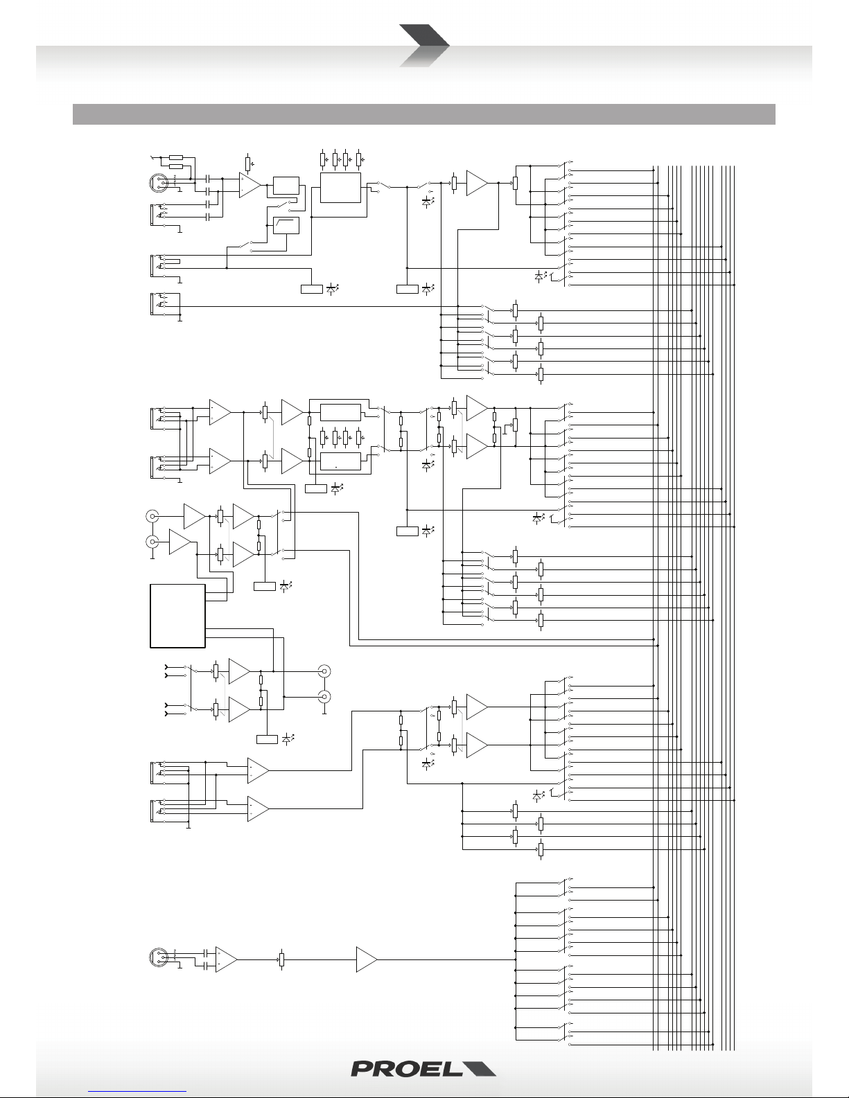
MONO INPUT CHANNELS CANALI INGRESSO MONO
Mic Input Sensivity from 0 to -50 dBu Balanced XLR-F Sensibilità Ingresso Mic da 0 a -50 dBu XLR-F Bilanciato
Mic Input Impedance 2 Kohm Impedenza Ingresso Mic 2 Kohm
Line Input Sensivity from +15 to -35 dBu Balanced Jack Sensibilità Ingresso Line da +15 a -35 dBu Jack Bilanciato
Line Input Impedance 10 Kohm Impedenza Ingresso Line 10 Kohm
LO CUT 75Hz, 18dB/oct. FILTRO LO-CUT 75Hz, 18dB/oct.
EQ HIGH (shelving) ±15 dB @ 12K Hz EQ ALTI (shelving) ±15 dB @ 12K Hz
HI-MID (peaking) ±15 dB 500-12K Hz MEDIO-ALTI (peaking) ±15 dB 500-12K Hz
LO-MID (peaking) ±15 dB 80-2K Hz MEDIO-BASSI (peaking) ±15 dB 80-2K Hz
LOW (shelving) ±15 dB @ 80 Hz BASSI (shelving) ±15 dB @ 80 Hz
INSERT nom. out level 0 dBu TRS Jack INSERT livello nominale 0 dBu Jack TRS
DIRECT OUT max. level +22 dBu Unbalanced Jack DIRECT OUT livello max +22 dBu Jack Bilanciato
STEREO INPUT CHANNELS CANALI INGRESSO STEREO
Line Input Sensivity from +15 to -35 dBu Balanced Jack Sensibilità Ingresso Line da +15 a -35 dBu Jack Bilanciato
Line Input Impedance 10 Kohm Impedenza Ingresso Line 10 Kohm
EQ HIGH (shelving) ±15 dB @ 12K Hz EQ ALTI (shelving) ±15 dB @ 12K Hz
HI-MID (peaking) ±15 dB @ 3 KHz MEDIO-ALTI (peaking) ±15 dB @ 3 KHz
LO-MID (peaking) ±15 dB @ 500 Hz MEDIO-BASSI (peaking) ±15 dB @ 500 Hz
LOW (shelving) ±15 dB @ 80 Hz BASSI (shelving) ±15 dB @ 80 Hz
MASTER SECTION SEZIONE MASTER
MAIN MIX max out level +28 dBu Balanced XLR-M MAIN MIX livello max +28 dBu XLR-M Bilanciato
GROUP max out level +28 dBu Balanced Jack GROUP livello max +28 dBu Jack Bilanciato
INSERT nom. out level 0 dBu TRS Jack INSERT nom. out level 0 dBu Jack TRS
AUX max out level +28 dBu Balanced XLR-M AUX livello max +28 dBu XLR-M Bilanciato
EQ HIGH (shelving) ±15 dB @ 12K Hz EQ ALTI (shelving) ±15 dB @ 12K Hz
MID (peaking) ±15 dB 500-12K Hz MEDI (peaking) ±15 dB 500-12K Hz
LOW (shelving) ±15 dB @ 80 Hz EQ BASSI (shelving) ±15 dB @ 80 Hz
MONITOR max out level +22 dBu Unbalanced Jack MONITOR livello max +22 dBu Unbalanced Jack
2 - TRK max out level +22 dBu Unbalanced Rca Livello max 2 - TRK OUT +22 dBu Rca Sbilanciato
2 - TRK nom. in level +22 dBu Unbalanced Rca Livello max 2 - TRK IN +22 dBu Rca Sbilanciato
PHONES max. out level 193 mW @ 32 ohm Stereo Jack Livello max PHONES 193 mW @ 32 ohm Jack Stereo
USB IN/OUT, 16bit / 48KHz Type B USB IN/OUT, 16bit / 48KHz Tipo B
DIGITAL EFFECT PROCESSOR - PROFEX DIGITAL EFFECT PROCESSOR - PROFEX
Equipped Eects 2Ee integra 2
Presets 256 (16 presets x 16 variaons) Presets 256 (16 preset x 16 variazioni)
A/D, D/A, DSP resoluon 24 bit Risoluzione A/D, D/A, DSP 24 bit
Controls 2-digit display, PRESET dial, TAP DELAY, MUTE Controlli 2 display LED, PRESET, TAP DELAY e MUTE
GENERAL MLX2842 MLX3642 GENERALI MLX2842 MLX3642
Crosstalk meas. at 1 KHz > 80 dB Diafonia mis. a 1 KHz > 80 dB
HUM & N unweighted < -93 dBu HUM & N non pesato < -93 dBu
THD+N at +20dBu, 1kHz < 0,03 % THD+N a +20dBu, 1kHz < 0,03 %
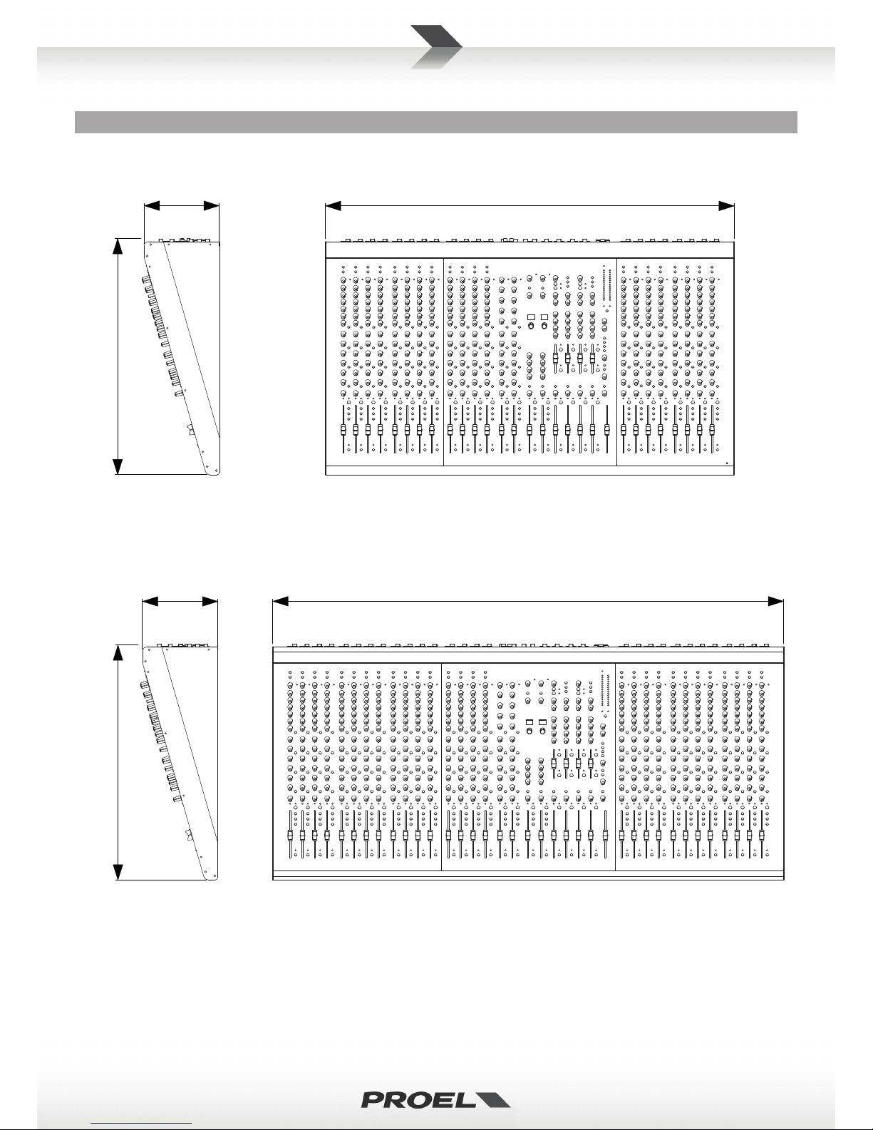
Dimensions (W x H x D) 900 x 170 x 515 mm 1125 x 170 x 515 mm Dimensioni (L x A x P) 900 x 170 x 515 mm 1125 x 170 x 515 mm
Weight 17.2 kg 21.1 kg Peso 17.2 kg 21.1 kg
POWER REQUIREMENTS MLX2842 MLX3642 ALIMENTAZIONE MLX2842 MLX3642
Mains Supply Voltage: 100-240 VAC (±10%) 50 / 60 Hz
available with Europe mains cord (Shucko plug),
US mains cord (NEMA 5-15P plug),
UK mains cord (BS1363 plug)
Tensione di Rete: 100-240 VAC (±10%) 50 / 60 Hz
disponibile con cavo rete Europa (spina Shucko),
cavo rete Sta Uni (spina NEMA 5-15P),
cavo rete Regno Unito (spina BS1363)
Consumpon 75 W 90 W Assorbimento 75 W 90 W
TECHNICAL SPECIFICATIONS SPECIFICHE TECNICHE

5
MECHANICAL DIMENSIONS DIMENSIONI MECCANICHE
112.5 cm
44.3"
90.0 cm
35.4"
17.0 cm
6.7"
17.0 cm
6.7"
51.5 cm
20.3"
51.5 cm
20.3"
MLX3642
MLX2842

6
BLOCK DIAGRAM (INPUTS) DIAGRAMMA A BLOCCHI (INGRESSI)
MIC IN 1-20 (28)
ST IN 1-2
2TRK IN
2TRK OUT
PHANTOM
POWER
+48V
MIC IN
LINE IN
LEFT (MONO)
LEFT
RIGHT
RIGHT
LEFT
RIGHT
MIC GAIN: 0~50dB
LINE IN TRIM: +15~-35dB
INSERT
DIRECT OUT
GAIN
(TRIM)
STEREO
GAIN
USB/2TRK
INPUT
USB/2TRK
OUTPUT
PLAYBACK
RECORD
Ø=180°
HI-PASS
LEVEL SET
LEVEL SET
LEVEL SET
80
100-2k
500-12k
12k
80
500
3k
12k
4-BAND EQ
+/-15dB
4-BAND EQ
80
500
3k
12k
4-BAND EQ
LO HI
LO-
MID HI-
MID
LO
HI
L-M
H-M
EQ ON/OFF
EQ ON/OFF
USB/2TRK
MUTE
MUTE
FADER
FADER
PAN
BAL
PEAK
+16dBu=OL
PEAK
+16dBu=OL
PEAK
+16dBu=OL
ASSIGN
LEFT
RIGHT
AFL-L
AFL-R
PFL-SOLO
LOGIC
GRP1
GRP2
GRP3
GRP4
LEFT
RIGHT
AFL-L
AFL-R
PFL-SOLO
LOGIC
GRP1
GRP2
GRP3
GRP4
ASSIGN
LEFT
RIGHT
AFL-L
AFL-R
PFL-SOLO
LOGIC
GRP1
GRP2
MAIN L
MAIN R
GRP1
GRP2
GRP3
GRP4
AUX1
AUX2
AUX3
AUX4
AUX5
AUX1
AUX3
AUX5
AUX6
AUX1
AUX2
AUX3
AUX4
AUX5
AUX6
AUX2
AUX4
AUX6
POST
PRE
AUX1
AUX2
AUX3
AUX4
AUX5
AUX1
AUX3
AUX5
AUX6
AUX2
AUX4
AUX6
POST
PRE
LEFT
RIGHT
TALKBACK
ASSIGN
TALKBACK
LEVEL
TALKBACK
LEFT
RIGHT
GRP1
GRP2
GRP3
GRP4
AUX1
AUX2
AUX3
AUX4
AUX5
AUX6
USB
LEFT
RIGHT
AFL-L
AFL-R
PFL-SOLO
LOGIC
GRP1
GRP2
GRP3
GRP4
AUX1
AUX2
AUX3
AUX4
AUX5
AUX6
SOLO
ST RETURN 1-2
LEFT (MONO)
RIGHT
MUTE
LEVEL
ASSIGN
LEFT
RIGHT
AFL-L
AFL-R
PFL-SOLO
LOGIC
GRP1
GRP2
GRP3
GRP4
AUX1
AUX2
AUX3
AUX4
AUX1
AUX3
AUX2
AUX4
PRE SOLO
SOLO

7
BLOCK DIAGRAM (OUTPUTS) DIAGRAMMA A BLOCCHI (USCITE)
LEFT
RIGHT
AFL-L
AFL-R
PFL-SOLO
LOGIC
GRP1
GRP2
GRP3
GRP4
AUX1
AUX2
AUX3
AUX4
AUX5
AUX6
LEFT
RIGHT
AFL-L
AFL-R
PFL-SOLO
LOGIC
GRP1
GRP2
GRP3
GRP4
AUX1
AUX2
AUX3
AUX4
AUX5
AUX6
MUTE
MAIN MIX
FADER
STEREO/MONOPRE/POST
MAIN B
LEVEL
BAL
LEFT
RIGHT
MAIN INSERT L
MAIN INSERT R
MAIN OUTPUT
LEFT (BALANCED)
MAIN OUTPUT
RIGHT (BALANCED)
MAIN B OUTPUT
LEFT (BALANCED)
MAIN B OUTPUT
RIGHT (BALANCED)
PAN
LEFT
RIGHT
AFL-L
AFL-R
PFL-SOLO
LOGIC
GRP1
MUTE
GROUP 1
FADER
GROUP 2,3,4 SAME AS GROUP 1
GROUP 1 INSERT
GROUP 1 OUTPUT
(UNBALANCED)
80
100-8k
12k
3-BAND EQ
+/-15dB
LO HI
MID
(FREQ)
AFL-L
AFL-R
PFL-SOLO
LOGIC
AUX1
SOLO
MUTE
AUX 1
FADER
AUX 2,3,4 SAME AS AUX 1
AUX 1 SEND
(BALANCED)
TO MAIN MIX
SOLO
PEAK
+16dBu=OL
AFL-L
AFL-R
PFL-SOLO
AFL PFL
MAIN R
METER R
METER L
MAIN L
PHONES
LEVEL
B
B
B
B
MONITOR
LEVEL
PHONES A
PHONES B
MONITOR L
MONITOR R
SOLO ACTIVE
SOLO MODE
FX1
ASSIGN
GRP1
GRP2
GRP3
GRP4
AFL-L
AFL-R
PFL-SOLO
LOGIC
AUX1
AUX5
AUX2
AUX3
AUX4
AUX1
AUX3
AUX2
AUX4
SOLO
LEFT
RIGHT
FX1
FADER
AUX6/FX2 SAME AS AUX5/FX1
AUX 5 SEND
(BALANCED)
FX1 SEND
LEVEL
AUX5 SEND
LEVEL
PEAK
ADC OL
PROFEX
24 BIT
DSP
MUTE
FX OUT L
FX OUT R
PRESET
TAP DELAY

8
MONO/STEREO CHANNEL CANALI MONO/STEREO
3
4
5
6
7
8
9
10
11
12
13
14
15
16
17
18
19
20
21
22
23
24
25
26
27
28
29
30
31
32
33
34
35
36
37
38
39
40
41
42
43
44
45
46
47
48
49
50
51
52
53
54
55
56
57
58
59
60
61
62
12
63
64

9
FX/AUX/RET FX/AUX/RET
65
66
67
68
69
70
71
72
73
74
75
76
77
78 79
80
81
82
83
84
85
86
87
88
89
90
91
92
93
94
95
96
97
98
99
100
101
102
103
104
107
108
109
110
111
112
113
114
115
106
116
105

10
OUT INS
1
GROUP/MAIN/PHONES/TALKBACK GROUP/MAIN/PHONES/TALKBACK
125
126
133
134
117
119
120
121
122
123
124
127
128
129
130
135
150
151
136
152
138
139
137
140
141
153
142
143
145
146
147
148
149
144
131
154
118
132
155

11
CONNECTIONS CONNESSIONI
SEND
RETURN
INSERT
Jack stereo
INSERT
Stereo Jack
LINE IN, OUT vari
Jack (bilanciato)
LINE IN, various OUT
Jack (balanced)
(2x) Jack mono (2x) Mono Jack
PHONES
Jack stereo
PHONES
Stereo Jack
MAIN MIX OUT
XLR bilanciato femmina
MAIN MIX OUT
Balanced female XLR
proel code: PFS29 or PFS24 (oponal)
Normally open momentary footswitch
Pedale a interruore momentaneo normalmente aperto
p - send
ring - return
sleeve - ground
p - send
p - return
sleeve - ground
ground
hot
cold
sleeve - ground
p - hot
ring - cold
MIC INPUT
XLR bilanciato maschio
MIC INPUT
Balanced male XLR
ground
hot
cold
p - le
ring - right
sleeve - ground
2TRK IN, OUT
Jack (sbilanciato)
2TRK IN, OUT
Jack (unbalanced)
ground
hot
cold
*nota: conneere insieme cold e ground
per cavi da bilanciato a sbilanciato
*note: connect both cold and ground to
make cable from balanced to unbalanced
LINE IN, OUT vari
Jack (sbilanciato)
LINE IN, various OUT
Jack (unbalanced)
ground
p - hot
cold
*nota: conneere insieme cold e ground
per cavi da bilanciato a sbilanciato
*note: connect both cold and ground
to make cable from balanced to unbalanced

12
ENGLISH LANGUAGE
SAFETY AND PRECAUTIONS
• CAUTION: before using this product read carefully the following safety instrucons. Take a look of this manual enrely and preserve it for
future reference.
When using any electric product, basic precauons should always be taken, including the following:
– To reduce the risk, close supervision is necessary when the product is used near children.
– Protect the apparatus from atmospheric agents and keep it away from water, rain and high humidity places.
– This product should be site away from heat sources such as radiators, lamps and any other device that generate heat.
– Care should be taken so that objects and liquids do not go inside the product.
– The product should be connected to a power supply mains line only of the type described on the operang instrucons or as marked on the
product. Connect the apparatus to a power supply using only power cord included making always sure it is in good condions.
– WARNING: The mains plug is used as disconnect device, the disconnect device shall remain readily operable.
– Power supply cord should be unplugged from the outlet during strong thunderstorm or when le unused for a long period of me.
– Do not place objects on the product’s power cord or place it in a posion where anyone could trip over, walk on or roll anything over it. Do not
allow the product to rest on or to be installed over power cords of any type. Improper installaons of this type create the possibility of re hazard
and/or personal injury.
IN CASE OF FAULT
• In case of fault or maintenance this product should be inspected only by qualied service personnel when:
– There is a aw either in the connecons or in the supplied connecng cables.
– Liquids have spilled inside the product.
– The product has fallen and been damaged.
– The product does not appear to operate normally or exhibits a marked change in performance.
– The product has been lost liquids or gases or the enclosure is damaged.
• Do not operate on the product, it has no user-serviceable parts inside, refer servicing to an authorized maintenance centre.
CE CONFORMITY
• Proel products comply with direcve 2004/108/EC (EMC), as stated in EN 55013 standard and with direcve 2006/95/CE (LVD), as stated in EN
60065 standard.
• Under the EM disturbance, the rao of signal-noise will be changed above 10dB.
PACKAGING, SHIPPING AND COMPLAINT
• This unit package has been submied to ISTA 1A integrity tests. We suggest you control the unit condions immediately aer unpacking it.
• If any damage is found, immediately advise the dealer. Keep all unit packaging parts to allow inspecon.
• Proel is not responsible for any damage that occurs during shipment.
• Products are sold “delivered ex warehouse” and shipment is at charge and risk of the buyer.
• Possible damages to unit should be immediately noed to forwarder. Each complaint for package tampered with should be done within eight
days from product receipt.
WARRANTY AND PRODUCTS RETURN
• Proel products have operang warranty and comply their specicaons, as stated by manufacturer.
• Proel warrants all materials, workmanship and proper operaon of this product for a period of two years from the original date of purchase. If
any defects are found in the materials or workmanship or if the product fails to funcon properly during the applicable warranty period, the owner
should inform about these defects the dealer or the distributor, providing receipt or invoice of date of purchase and defect detailed descripon.
This warranty does not extend to damage resulng from improper installaon, misuse, neglect or abuse. Proel S.p.A. will verify damage on returned
units, and when the unit has been properly used and warranty is sll valid, then the unit will be replaced or repaired. Proel S.p.A. is not responsible
for any "direct damage" or "indirect damage" caused by product defecveness.
INSTALLATION AND DISCLAIMER
• Proel products have been expressly designed for audio applicaon, with signals in audio range (20Hz to 20kHz). Proel has no liability for damages
caused in case of lack of maintenance, modicaons, improper use or improper installaon non-applying safety instrucons.
• Proel S.p.A. reserves the right to change these specicaons at any me without noce.
• Proel S.p.A. declines any liability for damages to objects or persons caused by lacks of maintenance, improper use, installaon not performed
with safety precauons and at the state of the art.
POWER SUPPLY AND MAINTENANCE
• Clean only with dry cloth.
• Before connecng the product to the mains outlet make certain that the mains line voltage matches that shown on the rear of the product, a
tolerance of up to ±10% is acceptable.
• CHECK THE CONDITION OF THE PROTECTION FUSE, ACCESSIBLE OUTWARD, ONLY WITH THE APPARATUS SWITCHED OFF AND
DISCONNECTED FROM THE MAINS LINE OUTLET.
• REPLACE THE PROTECTION FUSE ONLY WITH SAME TYPE AS SHOWN ON THE PRODUCT.
• IF AFTER THE SUBSTITUTION, THE FUSE INTERRUPTS AGAIN THE APPARATUS WORKING, DO NOT TRY AGAIN THEN CONTACT
THE PROEL SERVICE CENTER.

13
GENERAL INFORMATION
Thank you for having chosen a PROEL product.
MLX2842 and MLX3642 are large format mixers combining a large number of channels with a full set of features
designed to t any professional sound reinforcement applicaon.
The 20 or 28 MONO input channels feature ultra-low noise, high-headroom preamps, able to capture the full range of
any instrument. The 4-band EQ with two sweep mids has a great response for tweaking your sound in the most musical
way, while the EQ ON/OFF switch allows instant comparison. Each model includes two STEREO channels with 4-band
EQ.
The 6 AUX sends can be set pre- or post-fader in pairs. AUX sends 1 to 4, with 60mm faders and 3-band EQ, provide
eecve control of the stage monitoring. AUX sends 5&6 can be routed to the two internal eects, to external outboard
or used as two addional monitor sends. Two STEREO RETURNS with full roung allow to connect external outboard or
two addional stereo instruments.
All the channels together with the four GROUPS and the MAIN MIX feature 100mm long-wearing high-quality faders for
the most accurate level control.
The MLX mixers include two 24-bit PROFEX digital eects able to provide 256 studio-grade gig-ready eect algorithms:
this allows to enhance your mix with natural high-resoluon reverb or delay eects without the need of external
outboard. The eects can be selected thru a convenient LED display and they can be freely routed to the monitor sends,
the groups and the main mix.
The MLX series features a built-in USB interface to get CD quality audio to and from your computer: thru the USB
interface you can play audio les from the PC or record your live performance directly on hard-disk. The MLX USB
interface oers the possibility to route the INPUT signal directly to the MAIN MIX or to STEREO channel 2 and to get the
OUTPUT signal from the MAIN MIX or from GROUPS 1&2.
The MLX MASTER secon oers plenty of services and useful features, such as a MAIN MUTE switch, a TALKBACK
secon and separate PHONES and MONITOR level controls. Two or three USB sockets are available for connecng 5V
USB LAMPS.
The intuive control surface layout and the color-coded ergonomic knobs of MLX mixers allow to locate easily each
funcon and makes them extremely easy to use. Both models are hosted in a rugged and road-proof metal chassis.
OPERATING INSTRUCTIONS
1. +48V phantom switch
This switch acvates the phantom power on each group of 4 MIC channel inputs. Most professional condenser
microphones require phantom power, which is a lower DC voltage delivered to the microphone on pin 2 and 3 of the
XLR microphone connector. Dynamic microphones do not require phantom power, however phantom power will not
harm most dynamic microphones should you plug one in while the phantom power is on. Check the manual of your
microphone to nd out for sure whether or not phantom power can damage it.
2. +48V phantom LED
This LED indicates the phantom power acvaon on each group of 4 MIC channel inputs.
3. MIC Input
This is a female XLR connector, which accepts a balanced microphone input from almost any type of microphone. The
XLR inputs are wire as follows:
Pin 1 = shield or ground
Pin 2 = + posive or “hot”
Pin 3 = - negave or “cold”
4. LINE Input
This is a ¼” (6.3mm) jack connector, which accepts a balanced or unbalanced line level input signal from almost any
source. When connecng a balanced signal, wire them as follows:
Tip = + posive or “hot”
Ring = - negave or “cold”
Sleeve = shield or ground
When connecng an unbalanced signal, wire them as follows:
Tip = + posive or “hot”
Sleeve = shield or ground
5. INSERT Input-output
This is where you connect serial eects such as compressors, equalizers, de-essers or lters. The nominal in/out level
is 0/+4 dBu. Specialty “Y” cables, developed just for these jacks, must be used. The ¼” (6.3mm) jack connector is wired
as follows:

14
Tip = send signal
Ring = return signal
Sleeve = shield or ground
6. DIRECT OUT output
This is where you connect a multrack recorder or DAW system. This output is low-impedance (150 ohms), capable of
driving any line-level device. The signal sent is picked up aer the channel fader.
7. PHASE switch
The PHASE switch reverses the phase of the signal at the balanced input. It can be also used when combining two
sources on the same instrument to avoid phase cancellaon.
8. LO CUT switch
This switch cuts bass frequencies below 75 Hz at a rate of 18 dB per octave. We recommend that you use the LO CUT
lter on every microphone applicaon that doesn't produce deep bass content or that could cause problems on deep
bass spectrum.
9. MONO CHANNEL GAIN Control
The gain control adjusts the input sensivity of the mic and line inputs. This allows the signal from mics and instruments
to be adjusted to opmal internal levels. If the signals are plugged into the XLR input there is a 0 dB of gain with the
knob turned all way down, rising up to 50 dB of gain fully up. When connected to the jack input of any channels, there
is 15 dB of aenuaon all way down and 45 dB of gain fully up.
10. LEVEL SET indicator
This LED lights when the input signal is a lile bit less than the 0dB nominal level, so it can be used to check quickly the
opmal gain level without pressing the PFL/SOLO buon and checking the level in details on the LED meters.
11. EQ secon HIGH control
This control gives you up to 15dB boost or cut at 12KHz with a “SHELVING” curve shape. Use it to increase or reduce
the sound “clarity” or “brightness”.
12. EQ secon HI-MID control
This control gives you up to 15 dB boost or cut at the frequency determined by the FREQ knob (see FREQ next) with a
"PEAKING" curve shape. Use it to add the sound "denion" or reduce the sound "harshness".
13. EQ secon FREQ control
This knob ranges from 500 Hz to 12 kHz and determines the center frequency for the HI-MID EQ. This allows you to
select the precise narrow band of frequencies you want to have aected by the HI-MID EQ.
14. EQ secon LO-MID control
This control gives you up to 15 dB boost or cut at the frequency determined by the FREQ knob (see FREQ next) with a
"PEAKING" curve shape. Use it to add the sound "presence" or reduce the sound "muddy" or "boxy".
15. EQ secon FREQ control
This knob ranges from 80 Hz to 2 kHz and determines the center frequency for the LO-MID EQ. This allows you to select
the precise narrow band of frequencies you want to have aected by the LO-MID EQ.
16. EQ secon LOW control
This control gives you up to 15dB boost or cut at 80Hz with a “SHELVING” curve shape. Use it to increase or reduce the
sound “punch”.
17. EQ ON switch
This switch turns on and o the EQ secon. It is useful to listen the sound dierence with or without equalizaon.
18. AUX 1 control
This control sends the channel signal to the AUX 1 output.
19. AUX 2 control
This control sends the channel signal to the AUX 2 output.
20. AUX 1-2 POST/PRE switch
This switch sets the AUX 1 and AUX 2 control sends as post or pre fader. As post the signal level depends on the posion
of the channel FADER, as pre it is independent. The pre-fader seng is preferable if you want to use the AUX send as
stage monitor, in order to have your stage mix independent from MAIN MIX.
21. AUX 3 control
This control sends the channel signal to the AUX 3 output.
22. AUX 4 control
This control sends the channel signal to the AUX 4 output.

15
23. AUX 3-4 POST/PRE switch
This switch sets the AUX 3 and AUX 4 control sends as post or pre fader. As post the signal level depends on the posion
of the channel FADER, as pre it is independent. The pre-fader seng is preferable if you want to use the AUX send as
stage monitor, in order to have your stage mix independent from MAIN MIX.
24. FX1/AUX 5 control
This control sends the channel signal to the AUX 5 output and to the internal FX1 DIGITAL EFFECT PROCESSOR.
25. FX2/AUX 6 control
This control sends the channel signal to the AUX 6 output and to the internal FX2 DIGITAL EFFECT PROCESSOR.
26. AUX 5-6 POST/PRE switch
The AUX pre-fader seng is preferable if you want to use the AUX send as stage monitor, in order to have your stage
mix independent from MAIN MIX, or the AUX post-fader seng is preferable if you want to use the internal FX1 and FX2
DIGITAL EFFECT PROCESSORS, maintaining the dry/wet eect mixing balance also if you move the channel fader.
27. PAN control
It adjusts the amount of channel signal sent to the 1/3/LEFT versus the 2/4/RIGHT outputs depending on bus
assignments. Use it to posion the sound origin in a panoramic stereo scene.
28. PEAK detector
If the PEAK LED ashes this means that the input signal is near to the CLIPPING point.
IMPORTANT: if the LED PEAK ashes reduce the level of the input signal using the GAIN control.
29. MUTE indicator
When the MUTE switch is engaged this LED lights.
30. MUTE switch
When you engage a channel’s mute switch, its signal disappears from these outputs: MAIN MIX, GROUP, AUX.
NOTE: the input channel signal is not completely muted by this switch, so you can listen to it thru headphones and
MONITOR outputs acng on the SOLO buon in PFL mode only (see SOLO MODE).
31. 1-2 switch
Engaging this switch you assign the channel signal to the GROUPS 1-2 bus regulated by the GROUPS 1-2 faders. You can
use the GROUPS 1-2 as separate outputs or, engaging the correspondent MAIN MIX switch, to create a submix for a set
of channels (all the drums channels, for instance): in this case you can control the assigned GROUPS 1-2 signals together
and independently from the rest of the mix.
32. 3-4 switch
Engaging this switch you assign the channel signal to the GROUPS 3-4 bus regulated by the GROUPS 3-4 faders. You can
use the GROUPS 3-4 as separate outputs or, engaging the correspondent MAIN MIX switch, to create a submix for a set
of channels (all the voices channels, for instance): in this case you can control the assigned GROUPS 3-4 signals together
and independently from the rest of the mix.
33. MAIN switch
Engaging this switch you assign the channel signal to the MAIN MIX bus regulated by the MAIN MIX fader. Typically, the
MAIN switch will be engaged on all channels except those assigned separately to the GROUPS.
34. SOLO indicator
If the SOLO LED lights this means that you have acvated the SOLO switch of this channel.
35. SOLO switch
This switch allows you to hear signals through your headphones or MONITOR outputs and to display the level on LED
meters. Use the SOLO in live sets to pre-listen channels before they are fed into the mix or just to check out a parcular
channel any me during a session. You can solo as many channels at a me as you like.
IMPORTANT: The solo signal is pre-fader if SOLO MODE is in PFL posion, so what you check is the signal entering the
channel. The solo signal is post-fader if SOLO MODE is in AFL posion, so what you check is the signal sent from the
channel fader to the MAIN MIX or GROUPS.
36. FADER LEVEL control
It adjusts the level of the channel signal and sends it to the MAIN MIX and/or to the GROUPS buses.
37. LINE L MONO Input
This is a ¼” (6.3mm) jack connector, which accepts a balanced or unbalanced line level input signal from almost any line
source. If the LINE R jack is not inserted, this channel operates like a MONO channel with this input as a single signal
source. Wiring is the same of previous paragraphs.
38. LINE R Input
This is a ¼” (6.3mm) jack connector, which accepts a balanced or unbalanced line level input signal from almost any line

16
source. This is used only in presence of LINE L jack input to use the channel as STEREO.
39. STEREO CHANNEL GAIN Control
The gain control adjusts the input sensivity of the line inputs. This allows the signal from instruments to be adjusted
to opmal internal levels. There is 15 dB of aenuaon all way down and 35 dB of gain fully up.
40. LEVEL SET indicator
This LED lights when the input signal is a lile bit less the 0dB nominal level, so it can be used to check quickly the
opmal gain level without pressing the PFL/SOLO buon and check the level in details on the LED meters.
41. EQ secon HIGH control
This control gives you up to 15dB boost or cut at 12KHz with a “SHELVING” curve shape.
42. EQ secon HI MID control
This control gives you up to 15 dB boost or cut at 3 KHz with a "PEAKING" curve shape.
43. EQ secon LO MID control
This control gives you up to 15 dB boost or cut at 500 Hz with a "PEAKING" curve shape.
44. EQ secon LOW control
This control gives you up to 15dB boost or cut at 80Hz with a “SHELVING” curve shape.
45. EQ ON switch
This switch turns on and o the EQ secon, it is useful to listen the sound dierence with or without equalizaon.
46. AUX 1 control
This control sends the channel signal to the AUX 1 output.
47. AUX 2 control
This control sends the channel signal to the AUX 2 output.
48. AUX 1-2 POST/PRE switch
This switch sets the AUX 1 and AUX 2 control sends as post or pre fader. As post the signal level depends on the posion
of the channel FADER, as pre it is independent. The pre-fader seng is preferable if you want to use the AUX send as
stage monitor, in order to have your stage mix independent from MAIN MIX.
49. AUX 3 control
This control sends the channel signal to the AUX 3 output.
50. AUX 4 control
This control sends the channel signal to the AUX 4 output.
51. AUX 3-4 POST/PRE switch
This switch sets the AUX 3 and AUX 4 control sends as post or pre fader. As post the signal level depends on the posion
of the channel FADER, as pre it is independent. The pre-fader seng is preferable if you want to use the AUX send as
stage monitor, in order to have your stage mix independent from MAIN MIX.
52. FX1/AUX 5 control
This control sends the channel signal to the AUX 5 output and to the internal FX1 DIGITAL EFFECT PROCESSOR.
53. FX2/AUX 6 control
This control sends the channel signal to the AUX 6 output and to the internal FX2 DIGITAL EFFECT PROCESSOR.
54. AUX 5-6 POST/PRE switch
The AUX pre-fader seng is preferable if you want to use the AUX send as stage monitor, in order to have your stage
mix independent from MAIN MIX. The AUX post-fader seng is preferable if you want to use the internal FX1 and FX2
DIGITAL EFFECT PROCESSORS, maintaining the dry/wet eect mixing balance also if you move the channel fader.
55. BAL control
It adjusts the amount of channel signal sent to the le versus the right outputs if the channel is used as MONO, or it
fades the LEFT or RIGHT signal amount if the channel is used as STEREO.
56. PEAK detector
If the PEAK LED ashes this means that the input signal is near to the CLIPPING point.
IMPORTANT: if the LED PEAK ashes reduce the level of the input signal using the GAIN control.
57. MUTE indicator
When the MUTE switch is engaged this LED lights.
58. MUTE switch
When you engage a channel’s mute switch, its signal disappears from these outputs: MAIN MIX, GROUP, AUX.
NOTE: the input channel signal is not completely muted by this switch, so you can listen to it thru headphones and

17
MONITOR outputs acng on the SOLO buon in PFL mode only (see SOLO MODE).
59. 1-2 switch
Engaging this switch you assign the channel signal to the GROUPS 1-2 bus regulated by the GROUPS 1-2 faders. You can
use the GROUPS 1-2 as separate outputs or, engaging the correspondent MAIN MIX switch, to create a submix for a set
of channels (all the drums channels, for instance): in this case you can control the assigned GROUPS 1-2 signals together
and independently from the rest of the mix.
60. 3-4 switch
Engaging this switch you assign the channel signal to the GROUPS 3-4 bus regulated by the GROUPS 3-4 faders. You can
use the GROUPS 3-4 as separate outputs or, engaging the correspondent MAIN MIX switch, to create a submix for a set
of channels (all the voices channels, for instance): in this case you can control the assigned GROUPS 3-4 signals together
and independently from the rest of the mix.
61. MAIN switch
Engaging this switch you assign the channel signal to the MAIN MIX bus regulated by the MAIN MIX fader. Typically, the
MAIN switch will be engaged on all channels except those assigned separately to the GROUPS.
62. SOLO indicator
If the SOLO LED lights this means that you have acvated the SOLO switch of this channel.
63. SOLO switch
This switch allows you to hear signals through your headphones or MONITOR outputs and to display the level on LED
meters. Use the SOLO in live sets to pre-listen channels before they are fed into the mix or just to check out a parcular
channel anyme during a session. You can solo as many channels at a me as you like.
IMPORTANT: The solo signal is pre-fader if SOLO MODE is in PFL posion, so what you check is the signal entering the
channel. The solo signal is post-fader if SOLO MODE is in AFL posion, so what you check is the signal sent from the
channel fader to the MAIN MIX or GROUPS.
64. FADER LEVEL control
It adjusts the level of the channel signal and sends it to the MAIN MIX and/or to the GROUPS buses.
65. AUX RETURN jack input
Unbalanced jack connectors of the auxiliary stereo input (note: the L input can be used as MONO if R input is le
unconnected). This input can be used for the return signal from outboard eects or for connecng any instrument or
equipment with a line output.
66. AUX RETURN LEVEL control
It adjusts the level of the AUX RETURN inputs and send it to the MAIN MIX and/or GROUPS.
67. MUTE indicator
When the MUTE switch is engaged this LED lights.
68. MUTE switch
When you engage a return channel’s mute switch, its signal disappears from these outputs: MAIN MIX, GROUP, AUX.
NOTE: the input channel signal is not completely muted by this switch, so you can listen to it thru headphones and
MONITOR outputs acng on the SOLO buon in PFL mode only (see SOLO MODE).
69. SOLO indicator
If the SOLO LED lights this means that you have acvated the SOLO switch of this channel.
70. SOLO switch
This switch allows you to hear signals through your headphones or MONITOR outputs and to display the level on LED
meters. Use the SOLO in live sets to pre-listen channels before they are fed into the mix or just to check out a parcular
channel anyme during a session. You can solo as many channels at a me as you like.
IMPORTANT: The solo signal is pre-fader if SOLO MODE is in PFL posion, so what you check is the signal entering the
channel. The solo signal is post-fader if SOLO MODE is in AFL posion, so what you check is the signal sent from the
channel fader to the MAIN MIX or GROUPS.
71. AUX RETURN TO AUX 1 level control
It adjusts the level of the AUX RETURN inputs and send it to the AUX 1 output (pre).
72. AUX RETURN TO AUX 2 level control
It adjusts the level of the AUX RETURN inputs and send it to the AUX 2 output (pre).
73. AUX RETURN TO AUX 3 level control
It adjusts the level of the AUX RETURN inputs and send it to the AUX 3 output (pre).
74. AUX RETURN TO AUX 4 level control
It adjusts the level of the AUX RETURN inputs and send it to the AUX 4 output (pre).

18
75. 1-2 switch
Engaging this switch you assign the channel signal to the GROUPS 1-2 bus regulated by the GROUPS 1-2 faders. You can
use the GROUPS 1-2 as separate outputs or, engaging the correspondent MAIN MIX switch, to create a submix for a set
of channels (all the drums channels, for instance): in this case you can control the assigned GROUPS 1-2 signals together
and independently from the rest of the mix.
76. 3-4 switch
Engaging this switch you assign the channel signal to the GROUPS 3-4 bus regulated by the GROUPS 3-4 faders. You can
use the GROUPS 3-4 as separate outputs or, engaging the correspondent MAIN MIX switch, to create a submix for a set
of channels (all the voices channels, for instance): in this case you can control the assigned GROUPS 3-4 signals together
and independently from the rest of the mix.
77. MAIN switch
Engaging this switch you assign the channel signal to the MAIN MIX bus regulated by the MAIN MIX fader. Typically, the
MAIN switch will be engaged on all channels except those assigned separately to the GROUPS.
78. 2TRK INPUT
Use these unbalanced RCA connectors to patch the output of a player, such as an analog tape deck, MP3 player, CD/DVD
player or a Personal Computer.
79. 2TRK OUTPUT
Use these unbalanced RCA connectors to send out the MAIN MIX or GROUP 1-2 signals to a recorder, such as an analog
tape or an A/D converter connected to a Personal Computer.
80. USB PORT socket
It routes the 2TRK OUT and the 2TRK IN through the USB port in crystal-clean, 16-bit, 44.1 kHz stereo digital audio. Use
the mixer as a high-quality soundcard for recording and playback with Windows and Macintosh computers.
VERY IMPORTANT INFORMATIONS:
- The internal USB soundcard needs a personal computer with a USB 2.0 port and a Windows (XP or later) or Mac OSX
(10.3 or later) Operang Systems.
- The internal USB soundcard DOESN'T REQUIRE A DEDICATE SOFTWARE DRIVER to work with Windows or Mac OSX.
- For in/out signal roung inside the computer and the DAW soware refer to the documentaon included with the
computer and DAW soware.
- Tipically, aer you have connected the USB cable and powered on the mixer, the mixer soundcard is visible from the
computer and DAW soware as: "USB Audio CODEC" (or with a similar name, depending on the OS version).
81. SIGN indicator
This LED lights when the input signal is a lile bit less the 0dB nominal level, so it can be used to check quickly the
opmal level without pressing the PFL/SOLO buon and check the level in details on the LED meters.
82. USB/2TRK INPUT LEVEL control
It adjusts the level of the 2TRK INPUT and USB input (audio signal from PC).
83. MAIN MIX / ST2 switch
This switch routes the 2TRK IN or USB input signal directly to MAIN MIX outputs or to the ST2 channel. Roung the signal
to ST2 channel, you can use all features of the stereo channel before sending the signal to the MAIN MIX: equalizaon,
aux sends and the internal eect processors.
84. 2 TRK OUT PEAK detector
If the peak LED ashes mean that the signal is too high, near to the clipping the output stage. In this case, reduce the
level of the USB/2TRK OUT level control.
85. USB/2TRK OUT LEVEL control
It adjust the level of signal sent to the 2TRK OUTPUT and to the USB port. This control is aer the MAIN MIX/GROUP
1-2 fader control.
86. MAIN MIX - GROUP 1-2 switch
This switch selects which signal is sent to the 2TRK OUT and to the USB port. Choosing the MAIN MIX signal you can
record a whole mix session such as a live performance. Choosing GROUP 1-2 you can record ll two dierent instruments
in two dierent tracks of your DAW recording soware, roung them thru GROUP 1 and GROUP 2 respecvely and using
the MAIN MIX for monitoring.
87-88. FX1/2 PRESETS selector and display
The internal PROFEX digital eect processor is built around a powerful DSP and 24bit AD/DA converters. It includes 16
dierent presets of studio-grade eect algorithm, each one featuring 16 dierent variaons of the internal parameters,
for a total of 256 eects available.

19
HOW TO USE THE PROFEX EFFECT:
- rotate the SELECTOR knob to choose the type of eect (preset) you want to use;
- to select a variaon of the preset, press and hold the knob unl the display ashes;
- rotate the knob and choose one of the 16 variaons available;
- press and hold again the knob unl the display stops ashing to conrm the selecon and to return back to the
preset selecon;
- set the FX1/2 SEND level at half posion, this is the level of whole channels send to the internal eect,
- send the signal to the eect with the FX1/2 (AUX5/6) control of the channel you want to add the eect to;
- raise up the FX1/2 LEVEL fader unl you hear the eect added to the original signal;
- adjust, if necessary, the whole FX1/2 SEND or FX1/2 (AUX5/6) controls just before the signal input clipping indicated
by the FX PEAK LED;
- re-adjust the FX1/2 LEVEL fader to combine the wet eected signal with the natural dry signal.
NOTE: the preset and the variaon selected in the PROFEX eect are kept in the memory even if you turn o the
mixer.
PRESET DESCRIPTIONS:
p 1. BRIGHT HALL - This type of reverb simulates the ambience of a grand concert hall. Dense, smooth reverb with
long pre delay and a lot of high frequency reecons. Works well with vocals, electric and acousc guitars, strings.
The VARIATIONS vary the decay me and the hall size from bigger [1] to smallest [16].
p 2. DARK HALL - This type of reverb simulates the ambience of a grand concert hall. Dense, smooth reverb with long
pre delay and a few of high frequency reecons. Works well with vocals, guitars, woodwinds.
The VARIATIONS vary the decay me and the hall size from bigger [1] to smallest [16].
p 3. BRIGHT ROOM - This type of reverb reproduces the more inmate ambience of natural room acouscs. Feature
a lot of early reecons with a lot of high frequency. Works well with vocals, woodwinds, strings, drums.
The VARIATIONS vary the decay me and the room size from bigger [1] to smallest [16].
p 4. DARK ROOM - This type of reverb reproduces the more inmate ambience of natural room acouscs. Feature a
lot lot of early reecons with a few of high frequency. Works well with vocals, ngered guitars, drums.
The VARIATIONS vary the decay me and the room size from bigger [1] to smallest [16].
p 5. VOCAL 1 (STAGE REVERB) - Amazing reverb designed for vocals with a long tail.
The VARIATIONS vary the decay me from long tail [1] to short tail [16], alternang plate, spring or hall types of
reverb.
p 6. VOCAL 2 (CLUB REVERB) - Amazing reverb designed for vocals with a dense tail.
The VARIATIONS vary the decay me from long tail [1] to short tail [16], alternang tape, hall or spring types of
reverb.
p 7. PLATE - This is a simulaon of metal plate reverb, as used on classic recordings from the ‘70s and ‘80s.
The VARIATIONS vary the decay me from long tail [1] to short tail [16].
p 8. STEREO DELAY - Echo eect with ping-pong of le and right channels.
The VARIATIONS vary from long delay mes [1] to short delay mes [16].
p 9. STEREO TAP DELAY - Like STEREO DELAY above with me set by the user TAP buon (22) just below.
The VARIATIONS vary from 5% [1] to 90% [16] of feedback quanty.
p 10. MONO TAP DELAY - Typical mono delay with me set by the user TAP buon (22) just below.
The VARIATIONS vary from 0% [1] to 75% [16] of feedback quanty.
p 11. CHORUS - Typical modulaon eect, provides a so, ethereal sweeping eect. Perfect for enhancement of
electric and acousc guitar and bass. Also adds a dramac eect to vocals, parcularly group harmonies and choirs.
The VARIATIONS increase the modulaon frequency from 0.5Hz [1] to 5Hz [16].
p 12. FLANGER - Typical modulaon eect, creates a strong sweeping eect, parcularly eecve on rock electric
guitar, lead and rhythm.
The VARIATIONS increases the modulaon frequency from 0.2Hz [1] to 3Hz [16].
p 13. REVERB+DELAY 1 - Typical vocal hall reverb and stereo delay combined together.
The VARIATIONS vary from long tail [1] to short tail [16].
p 14. REVERB+DELAY 2 - Typical vocal hall reverb and mono delay combined together.
The VARIATIONS vary from long tail [1] to short tail [16].
p 15. REVERB+TAP DELAY - Typical vocal hall reverb and mono TAP delay combined together.
The mono delay me is set by the user TAP buon (22) just below.
The VARIATIONS vary from long tail [1] to short tail [16] and from 0% to 75% of feedback quanty [1-16].
p 16. REV+CHORUS - Typical vocal reverb and chorus eect combined together.
The VARIATIONS vary from long tail [1] to short tail [16] and increases the modulaon frequency from 0.5Hz to 5Hz
[1-16].

20
89. FX TO AUX1 level control
It adjusts the level of the internal eect signal sent to the AUX 1 output.
90. FX TO AUX2 level control
It adjusts the level of the internal eect signal sent to the AUX 2 output.
91. FX TO AUX3 level control
It adjusts the level of the internal eect signal sent to the AUX 3 output.
92. FX TO AUX4 level control
It adjusts the level of the internal eect signal sent to the AUX 4 output.
93-94. TAP buon and LED
When “TAP DELAY” eects (p 9, 10, 15) are selected, by pushing at least two mes this buon it’s possible to set the
desired delay me, according to music rhythm. The TAP LED ashes in sync with the delay me set.
95. FX1/2 SEND level control
It adjusts the master level of FX1/2 signal sent to internal eect. Use it to reduce the level of signal sent to the internal
eect if the PEAK LED is ashing. This control ranges from o to max fully clockwise.
96. PEAK detector
If the peak LED ashes this means that the signal is too high, near to the clipping of the eect input stage. In this case,
reduce the level of the single channel FX1/2 (AUX5/6) send or of the master FX1/2 SEND.
97. MUTE indicator
When the MUTE switch is engaged this LED lights.
98. MUTE buon
Engage this switch if you want to mute the signal from the internal eect.
99. 1-2 switch
Engaging this switch you assign the FX output signal to the GROUPS 1-2 bus regulated by the GROUPS 1-2 faders.
100. 3-4 switch
Engaging this switch you assign the FX output signal to the GROUPS 3-4 bus regulated by the GROUPS 3-4 faders.
101. MAIN switch
Engaging this switch you assign the FX output signal to the MAIN MIX bus regulated by the MAIN MIX fader.
102. SOLO indicator
If the SOLO LED lights this means that you have acvated the SOLO switch of the internal eect.
103. SOLO switch
This switch allows you to hear the signals of FX output through your headphones or MONITOR outputs and to display
the level on LED meters.
104. FX FADER LEVEL control
It adjusts the level of the internal eect signal sent to the MAIN MIX or GROUP outputs.
105. AUX SEND 5-6 jack output
This jack connector sends out balanced line-level signals made of the sum of the AUX 5 or 6 busses.
106. AUX SEND 1-4 XLR output
This jack connector sends out balanced line-level signals made of the sum AUX 1, 2, 3 or 4 busses, usually for connecng
to the inputs of external eect devices or stage monitor.
107. EQ secon HIGH control
This control gives you up to 15dB boost or cut at 12KHz with a “SHELVING” curve shape.
108. EQ secon MID control
This control gives you up to 15 dB boost or cut at the frequency determined by the FREQ knob (see FREQ next) with a
"PEAKING" curve shape.
109. EQ secon FREQ control
This knob ranges from 100 Hz to 8 kHz and determines the center frequency for the MID EQ. This allows you to zero in
on the precise narrow band of frequencies you want to have aected by the MID EQ.
110. EQ secon LOW control
This control gives you up to 15dB boost or cut at 80Hz with a “SHELVING” curve shape.
111. MUTE indicator
When the MUTE switch is engaged this LED lights.
This manual suits for next models
1
Table of contents
Languages:
Other PROEL Music Mixer manuals