AudioArts Engineering Audioarts 08 User manual

Technical Manual
December 2015
AudioArts 08
Radio Console

AUDIOARTS Radio Console Technical Manual
©2015 Audioarts®Engineering*
AUDIOARTS ENGINEERING
600 Industrial Drive
New Bern, North Carolina 28562
252-638-7000
*a division of Wheatstone Corporation
AUDIOARS / Dec 2015

page Contents – 1
AUDIOARTS 08 / Dec 2015
CONTENTS
AUDIOARTS 08 Technical Manual
Chapter 1 - Information and Power
Chapter 2 - Console Features
Table of Contents
Unpacking and Installing the Console ........................................1-2
Power Supply .................................................................................1-3
Energizing ......................................................................................1-3
Audio and Control Wiring .............................................................1-4
Unbalanced Connections (analog audio) ...................................................................1-5
Hook-Ups ........................................................................................1-6
MIC 1 and MIC 2 Inputs - XLR ...................................................................................1-6
LINE 3 IN through LINE 6 IN and LINE 8 IN ...............................................................1-6
CALLER IN - RJ-45 ....................................................................................................1-7
MXM-TB OUT - RJ-45................................................................................................1-7
TALLY OUT - RJ-45 ....................................................................................................1-7
PGM OUT - XLR.........................................................................................................1-7
Overview .........................................................................................2-2
Inputs ..............................................................................................2-3
Analog Mono Mic Level Inputs...................................................................................2-3
Analog Stereo Line Level Inputs.................................................................................2-3
Outputs ...........................................................................................2-3
Program Output..........................................................................................................2-4
Monitor Output ...........................................................................................................2-4
Cue to Monitor ......................................................................................................2-4
Split Cue, Monitor .................................................................................................2-4
On Air Tally, Muting................................................................................................2-4
USB Port .........................................................................................2-5
Using the USB Port... .................................................................................................2-5
... With a MAC ............................................................................................................2-5
... With a Windows®PC .............................................................................................2-5
Other Computers........................................................................................................2-5
General Considerations..............................................................................................2-6
AUDIOARTS 08 / Mar 2019

page Contents – 2
AUDIOARTS 08 / Dec 2015
CONTENTS
Input Section..................................................................................3-2
Source ........................................................................................................................3-2
Cue Button .................................................................................................................3-3
TB Button ...................................................................................................................3-3
Fader ..........................................................................................................................3-3
ON Button ..................................................................................................................3-3
Control Room and Headphone Section.......................................3-4
Control Room .............................................................................................................3-4
Headphone Fader.......................................................................................................3-5
Meters.............................................................................................3-5
Console Flow Diagram..................................................................4-2
Mother Board
Schematic ..................................................................................................................4-3
Load Sheet ................................................................................................................4-12
Replacement Parts List.................................................................A-2
Chapter 3 - Controls and Functions
Chapter 4 - Schematic and Load Sheet Drawings
Appendix

page 1 – 1
AUDIOARTS 08 / Dec 2015
INSTALLATION AND POWER
Installation and Power
Unpacking and Installing the Console ........................................1-2
Power Supply.................................................................................1-3
Energizing ......................................................................................1-3
Audio and Control Wiring .............................................................1-4
Unbalanced Connections (analog audio) ...................................................................1-5
Hook-Ups........................................................................................1-6
MIC 1 and MIC 2 Inputs - XLR ...................................................................................1-6
LINE 3 IN through LINE 6 IN and LINE 8 IN ...............................................................1-6
CALLER IN - RJ-45 ....................................................................................................1-7
MXM-TB OUT - RJ-45................................................................................................1-7
TALLY OUT - RJ-45 ....................................................................................................1-7
PGM OUT - XLR.........................................................................................................1-7
Chapter Contents

page 1 – 2
AUDIOARTS 08 / Dec 2015
INSTALLATION AND POWER
Installation and Power
Unpacking and Installing the Console
The AUDIOARTS 08 console with its power supply, AC connecting
cable, and Installation and Connections Quick Reference is shipped in one
packing box. The console can be unpacked by one person by grasping the
console at both sides, and lifting it upward out of the box. Remove packing
materials and store them in the box for future use. Carefully place the
console on your countertop (theAUDIOARTS 08 audio console is designed
for countertop placement). Avoid proximity to any electromagnetic elds,
such as large power transformers, motors, and uorescent lighting xtures.
NOTE: This console
contains static-sensitive
devices. Normal pre-
cautions against static
discharge should be ob-
served.
10-5 /16 10-5/16
16-1/2 2- 5/16
1

page 1 – 3
AUDIOARTS 08 / Dec 2015
INSTALLATION AND POWER
Power Supply
TheAUDIOARTS 08 console is powered by a fac-
tory supplied power adapter with 100-240V/50-60Hz
input, 25W maximum output power, and a 4 foot
long output cable.
DC Power Output Pinout
The power supply adapter is supplied with a 3_wire grounded AC cord
that should be plugged into a “clean” AC power source, that is, an AC
source that feeds only the control room audio gear. This source should
be a separate feed from those powering lighting, air-conditioning, or any
other non-audio machinery.
Energizing
Assuming the AUDIOARTS 08 console mainframe is properly placed,
and its power supply correctly connected to the console, you may now
energize the power supply adapter by plugging it into the AC mains. The
console’s switches will assume factory default settings.
Note: To de-energize the console, unplug the power supply adapter’sAC
cord from the AC mains. Never de-energize the console by disconnecting
the cable that connects the console and power supply adapter together.
The power feed recom-
mended in the text is often
installed and referred to in
studios as an “isolated AC
ground” outlet. It is usually
orange in color.
PIN # OUTPUT
1 COM
2 COM
3 +5VDC
4 -15V
5 +15V
3
524
1
Once you have veried proper power-up, unplug the rackmount power
supply to de-energize the control surface. You may now proceed to wire
up audio and control connections
page 1 – 4
AUDIOARTS 08 / Dec 2015
INSTALLATION AND POWER
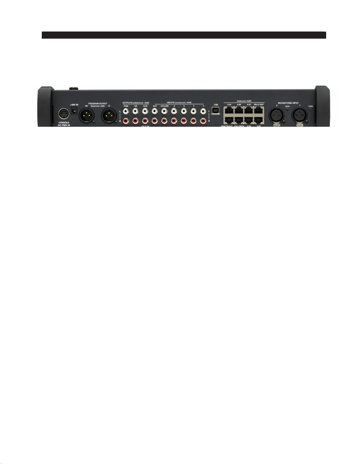
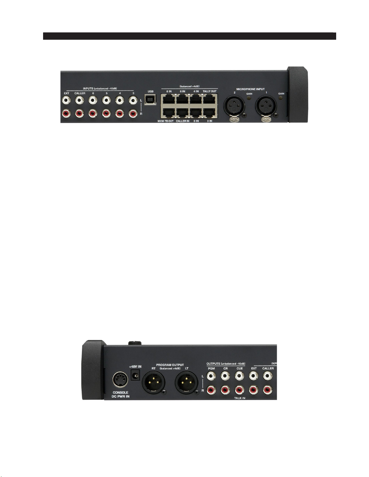
Audio and Control Wiring
All audio I/O connections to the AUDIOARTS 08 console are made via XLR, RCA
and RJ-45 connectors located on the rear panel of the console.
Two XLR female connectors are provided to bring balanced mono microphone level
signals into the console for control by the rst two (microphone) faders. These XLR
connectors are wired “pin 2 hot.”
Six RJ-45 connectors are provided to bring balanced stereo line level signals into the
console for control by (line) faders three through six and eight. Four pairs of RCA jacks
are provided to bring unbalanced stereo line level signals into the console for control by
(line) faders three through six.
The MXM-TB OUT RJ-45 connector is provided to bring the stereo balanced line level
MXM output and the mono unbalanced line level TB OUT out of the console.
A stereo balanced CALLER input signal is provided on the CALLER IN RJ-45 con-
nector for fader seven. One pair of RCA jacks (CALLER) is provided to bring in an un-
balanced stereo CALLER signal. Note that most phone hybrids are mono, so if you are
using fader seven for a phone caller you will need to wire the mono caller signal to both
left and right inputs in parallel. If you are not using fader seven for a caller input you can
use it for a stereo source.
One pair of RCA jacks (EXT) is provided to bring an additional stereo line level signal
into the console for use by the monitor circuits.
One pair of RCA jacks is provided to bring stereo program output out of the console
as unbalanced -10dB signal. Two XLR male connectors are provided to bring the stereo
program output out of the console as balanced line level +4dBu signal.
One pair of RCA jacks is provided to bring the stereo monitor output out of the con-
sole as separate (left and right) unbalanced line level signals at a nominal level of -2dBu
(equivalent to one side of a balanced +4dBu output).
One pair of RCA jacks is provided to bring the mono cue (L) out of the console and
the talk in (R) to the console as an unbalanced line level signal (nominal -10dBu).
The TALLY OUT RJ-45 connector is provided to hook up an interface to an Air Tally
light. This output comes from a set of relay contacts and is designed to switch a low DC
voltage (30 VDC maximum) at a moderately low current (2 ADC maximum) to activate
a DC light, or to activate an external DC relay which can then be used to activate an AC
operated light. Never bring AC power into the console on this or any other connector.
The USB type B connector in the center of the rear panel is used for interfacing with
a computer (see page 2-5 for details).
A 5-pin DIN connector is provided to accept console power from the external power
supply.
There is also a phantom power 2.5mm +48V IN power jack as a way to connect external
power source (not provided) for condenser microphones and direct boxes.

page 1 – 5
AUDIOARTS 08 / Dec 2015
INSTALLATION AND POWER
One TRS jack is provided on the right side of
the console frame for the operator to plug in a set of
headphones. This is wired as a standard headphone
jack, with the left signal on the tip, the right signal on
the ring, and the sleeve connected to ground.
Unbalanced Connections (analog audio)
ANALOG INPUTS – Wire to the console (other than the RJ-45 connectors) with
typical shielded two conductor cable (like Belden 9451), just as if you were connecting
a balanced source. At the unbalanced source machine’s output, connect the black wire
(LO) to the shield.
ANALOG OUTPUTS — TheAUDIOARTS 08 console’s PGM line level analog out-
puts are electronically balanced, low impedance, outputs, expecting a minimum load of
600 ohms. The outpus are balanced but not oating. Therefore, care must be exercised
when connecting them to an unbalanced system. While temporarily shorting the low
side of the output signal to ground will not cause any problems, continued operation
under these conditions will result in increased distortion, decreased reliability, and pos-
sible oscillation problems. If you must connect this output to an unbalanced system,
be sure to leave the low side unterminated, and connect the unbalanced system to
the high side output and shield connections only.
page 1 – 6
AUDIOARTS 08 / Dec 2015
INSTALLATION AND POWER
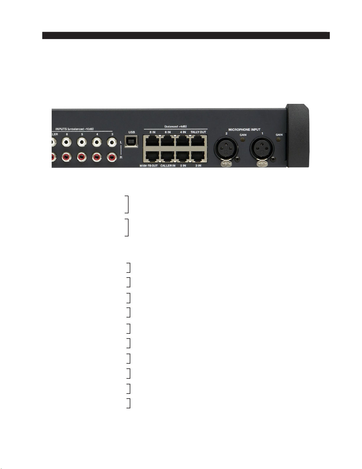
Hook-Ups
The rear of the console has multiple RJ-45 and RCAconnectors to plug in four stereo line
inputs, caller and external inputs, as well as providing program, monitor, cue, MXM-TB, and
tally output connections. There are also two female XLR connectors provided for microphone
MIC 1 and MIC 2 inputs and two male XLR connectors for program output connection.
Line 3 Lt In
Line 3 Rt In
Mic 1 In
Mic 2 In
Four pairs of RCA jacks (3 - 6) are for analog stereo unbalanced -10dBu signals. The
top RCA jack is Left and bottom RCA jack is Right for each channel.
MIC 1 and MIC 2 Inputs – XLR
All signals are analog mono. The mic input level is normally -50dBu balanced.
XLR 1 Pin 1 – SH
XLR 1 Pin 2 – HI
XLR 1 Pin 3 – LO
XLR 2 Pin 1 – SH
XLR 2 Pin 2 – HI
XLR 2 Pin 3 – LO
LINE 3 IN through LINE 6 IN and LINE 8 IN – RJ-45
All signals are analog stereo. The line input level is normally +4dBu balanced.
RJ-45#3 Pin 1 – HI
RJ-45#3 Pin 2 – LO
RJ-45#3 Pin 3 – HI
RJ-45#3 Pin 6 – LO
RJ-45#4 Pin 1 – HI
RJ-45#4 Pin 2 – LO
RJ-45#4 Pin 3 – HI
RJ-45#4 Pin 6 – LO
RJ-45#5 Pin 1 – HI
RJ-45#5 Pin 2 – LO
RJ-45#5 Pin 3 – HI
RJ-45#5 Pin 6 – LO
RJ-45#6 Pin 1 – HI
RJ-45#6 Pin 2 – LO
RJ-45#6 Pin 3 – HI
RJ-45#6 Pin 6 – LO
RJ-45#8 Pin 1 – HI
RJ-45#8 Pin 2 – LO
RJ-45#8 Pin 3 – HI
RJ-45#8 Pin 6 – LO
Line 4 Lt In
Line 4 Rt In
Line 5 Lt In
Line 5 Rt In
Line 6 Lt In
Line 6 Rt In
Line 8 Lt In
Line 8 Rt In

page 1 – 7
AUDIOARTS 08 / Dec 2015
INSTALLATION AND POWER
CALLER IN – RJ-45
The signal is analog stereo, +4dBu balanced.
RJ-45 Pin 1 – HI
RJ-45 Pin 2 – LO
RJ-45 Pin 3 – HI
RJ-45 Pin 6 – LO
MXM-TB OUT – RJ-45
The MXM signal is analog stereo and the TB signal is mono. Both signals are
+4dBu balanced.
RJ-45 Pin 1 – HI
RJ-45 Pin 2 – LO
RJ-45 Pin 3 – HI
RJ-45 Pin 6 – LO
RJ-45 Pin 7 – HI
RJ-45 Pin 8 – LO
TALLY OUT – RJ-45
Relay closure, 30VDC, 2A maximum.
RJ-45 Pin 4 – Tally N.O.
RJ-45 Pin 5 – Tally COM
PGM OUT – XLR
The signal is analog stereo, level is +4dBu balanced.
XLR LT Pin 1 – SH
XLR LT Pin 2 – HI
XLR LT Pin 3 – LO
XLR RT Pin 1 – SH
XLR RT Pin 2 – HI
XLR RT Pin 3 – LO
One pair of RCAjacks (PGM) is for analog stereo unbal-
anced -10dBu PGM Out signal. The top RCA jack is Left
and bottom RCA jack is Right for this output.
Caller Lt In
Caller Rt In
MXM Lt Out
MXM Rt Out
TB Out
PGM Lt Out
PGM Rt Out
NOTE:
If you are using this input with a
mono caller signal from a phone
hybrid you will need to wire to left
and right inputs in parallel.

page 2 – 1
AUDIOARTS 08 / Dec 2015
CONSOLE FEATURES
Console Features
Overview .........................................................................................2-2
Inputs ..............................................................................................2-3
Analog Mono Mic Level Inputs...................................................................................2-3
Analog Stereo Line Level Inputs.................................................................................2-3
Outputs ...........................................................................................2-3
Program Output..........................................................................................................2-4
Monitor Output ...........................................................................................................2-4
Cue to Monitor ......................................................................................................2-4
Split Cue, Monitor .................................................................................................2-4
On Air Tally, Muting................................................................................................2-4
USB Port .........................................................................................2-5
Using the USB Port... .................................................................................................2-5
... With a MAC ............................................................................................................2-5
... With a Windows®PC .............................................................................................2-5
Other Computers........................................................................................................2-5
General Considerations..............................................................................................2-6
Chapter Contents
AUDIOARTS 08 / Mar 2019
page 2 – 2
AUDIOARTS 08 / Dec 2015
CONSOLE FEATURES
Console Features
Overview
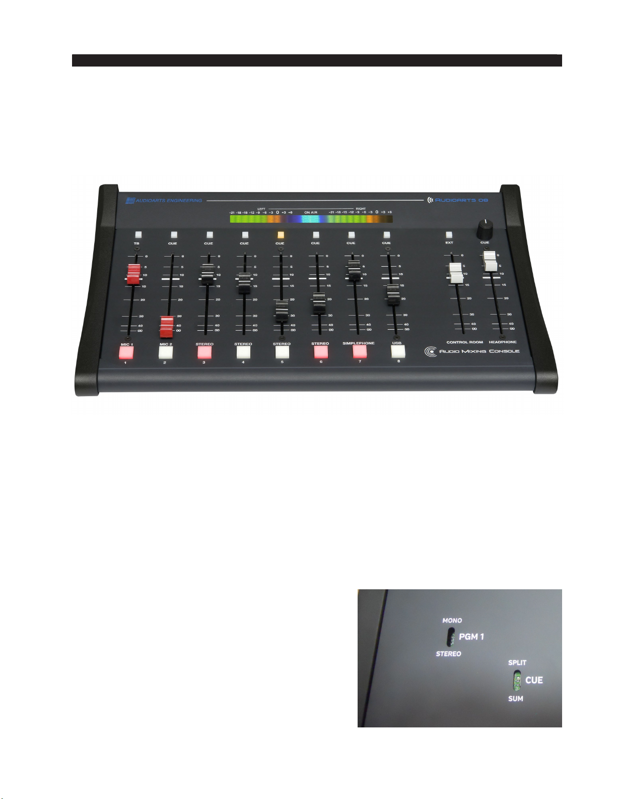
The AUDIOARTS 08 console consists of an input section with eight faders and
associated switches, monitor and headphone section with two faders and associated
switches.
The basic purpose of the console is to take some of the many audio signals that are
wired to the console inputs, and generate several
outputs that combine these inputs in various groups
and at various degrees of loudness, or signal strength.
The typical application is in a radio station where it
is desired to develop the signals that the station will
broadcast (the on air signal), as well as additional
signals for recording and monitoring.
All programming is made via PCB mounted slide
switches accessible through openings in the console’s
bottom panel.
page 2 – 3
AUDIOARTS 08 / Dec 2015
CONSOLE FEATURES
Inputs
The AUDIOARTS 08 console is designed to handle several analog stereo balanced
(+4dBu) inputs via RJ-45 connectors or stereo unbalanced (-10dBu) inputs via RCA
connectors. Inputs may also include caller audio from a telephone hybrid. Two mono
microphone balanced (-50dBu) inputs are also available, and there is one external stereo
line level balanced (+4dBu) input that goes directly to control room or meter. A USB
connector allows audio to pass between the AUDIOARTS 08 and a computer. There is
also a mono TALK IN input that allows an external line level source to directly feed the
console CUE output.
Analog Mono Mic Level Inputs
These inputs are used to connect to microphones, which typically put out signals at
relatively low signal strength, and therefore require more amplication (increase in signal
strength) to be properly audible in the output. Mic level sources are wired to female XLR
connectors located on the rear of the console. These mic inputs feed the console’s rst two
faders. The mic preamps are set for a gain of 54dBu, but each mic pre has its own recessed
GAIN control, located adjacent to the XLR input connector, to allow eld adjustment to
compensate for differences in microphone characteristics.
Example: with a microphone input of –60dBm @150 ohm at the port, gain trim
can set levels from -22dBu to +16dBu (note maximum preamp gain is +76dB) at the
PGM output.
Analog Stereo Line Level Inputs
These inputs are typically used to connect to machines, such as tape decks, cart
machines, CD players, etc., that provide analog outputs.
Outputs
The console outputs include an MXM-TB output, the program stereo bus, a stereo
monitor output, a mono cue output, and a stereo headphone jack.
The console’s mono cue signal is provided to drive an external powered speaker, or
amplier and speaker combination, and also provides the cue signal used to interrupt monitor
and headphones, if such interrupt has been enabled by the installer.

page 2 – 4
AUDIOARTS 08 / Dec 2015
CONSOLE FEATURES
Program Output
The console’s main analog output is the Program stereo bus. The Program stereo output
can be programmed to mono output via slide switch, PGM (SW 1 on MBA0-1 PCB).
When SW1 is UP the PGM is in mono mode, which sums the left and right PGM
channels and sends this mono signal to both left and right channels of the PGM 1 output.
When SW1 is DOWN the PGM is in stereo mode.
Monitor Output
TheAUDIOARTS 08 has a CR output designed to drive a stereo pair
of powered speakers, or a stereo amplier driving separate speakers,
to allow the operator to listen to PGM 1, or an external signal. The
console may be programmed to provide monitor split cue.
Cue to Monitor
The CUE TO MONITOR jumper J1 on the MBA0-1 PCB, when
shunted, sends cue to the monitor, whenever a fader is placed in cue.
Split Cue, Monitor
The CUE (SW2 on MBA0-1 PCB) slide switch, when activated (UP), allows a summed
(L+R) version of the regular program to be sent to the right side of the monitor stereo output,
while CUE is sent to the left side.
On Air Tally, Muting
For controlling an external “on-air” indicator, a relay is provided. The tally is activated
when a mic channel set for monitor mute is turned on. Jumper J2 on the MBA0-1 board is
used to enable muting with MIC1, and J3 enables muting with MIC2.
The relay connections are available at the “TALLY” RJ-45 connector mounted on the
rear of the console. Connect the on-air light to the external user-provided relay. Do not
bring on-air light AC connections to any pin of any connector on the console.
PIN
5
CONNECTOR PIN
TALLY OUT RJ-45
YOUR
POWER
SUPPLY
–
TYPICAL CONTROL ROOM ON-AIR TALLY CIRCUIT
USER-SUPPLIED RELAY TRIGGERED BY CONSOLE CR MUTE CIRCUIT
PIN
4
+
INTERNAL AIR
TALLY RELAY
COM
+
–
1N4002
ECG
B40240
or equiv.
relay
RELAY CIRCUIT POWERED BY USER
SUPPLIED EXTERNAL SUPPLY
N.O.
N.C.
2A
max
30VDC

page 2 – 5
AUDIOARTS 08 / Dec 2015
CONSOLE FEATURES
AUDIOARTS 08 / Mar 2019
USB Port
The console contains a USB 2.0 interface, available via the
USB Type B connector on the rear panel, to enable audio to
pass between the console and a USB port on a computer. Audio
coming back from the computer via USB shows up as a stereo
analog signal on the Line 8 fader. Audio to the computer will
be from the AUDIOARTS 08 PGM bus.
Using the USB Port . . .
Any computer having a USB port and installed drivers capable of passing and utilizing
digital audio data should work with the AUDIOARTS 08 USB port. Use a cable having a
USB Type B connector on the AUDIOARTS 08 end and a connector on the other end that
will mate with the computer’s USB port; this will typically be a USB Type A connector.
. . . With a MAC
In general, this will be a plug-and-play process. The main concern is to choose the
USB Audio Codec under System Preferences>Sound as desired for audio input and/or
output. Then simply start the application.
. . . With a Windows® PC
When you rst connect the AUDIOARTS 08 USB port to a PC running Windows you
will see the famous “found new hardware” sequence of messages. At some point this
sequence should end with a message that the new hardware is installed and ready to use.
Setting up any given application to use the AUDIOARTS 08 USB port will depend
on the application itself. Generally, you will need to select the appropriate device from a
list of devices in a Preferences dialog.
As an example, let’s look atAudacity.Audacity is a free, easy-to-use, multi-track audio
editor and recorder for Windows, Mac OS X, GNU/Linux and other operating systems.
It allows you to easily select audio inputs and outputs.
Select the USB Audio CODEC for input and output. You will be able to record audio
from the AUDIOARTS 08 console and when you play it back, the audio will appear on
the 8 IN fader, unless you have an audio source plugged into the 8 IN RJ-45 connector.
Other Computers
If your computer does not use one of the above operating systems, or otherwise behaves
differently than described above, consult the documentation for that computer, operating
system, and/or application.

page 2 – 6
AUDIOARTS 08 / Dec 2015
CONSOLE FEATURES
AUDIOARTS 08 / Mar 2019
General Considerations
If any problems are encountered, please consider the following points:
• The audio coming back into the AUDIOARTS 08 on the USB port is available at
the 8 IN fader.
• If you are not able to get the audio into or out of the USB port, check the USB
cable, its connections at both ends, and the port selection settings in the application
you are using.
• If you have the audio owing where you want and it suddenly becomes intermittent
or disappears, check the USB cable and the connections at both ends.
• Once you have the USB audio under control it is a good idea to make a record of
the application being used, including its version number, the audio direction (into
or out of the computer), and all the settings that were required to make it work. This
information will be invaluable if you later have to troubleshoot the USB audio, or
set it up on another computer.

page 3 – 1
AUDIOARTS 08 / Dec 2015
CONTROLS AND FUNCTIONS
Controls and Functions
Input Section..................................................................................3-2
Source ........................................................................................................................3-2
Cue Button .................................................................................................................3-3
TB Button ...................................................................................................................3-3
Fader ..........................................................................................................................3-3
ON Button ..................................................................................................................3-3
Control Room and Headphone Section.......................................3-4
Control Room .............................................................................................................3-4
Headphone Fader.......................................................................................................3-5
Meters.............................................................................................3-5
Chapter Contents

page 3 – 2
AUDIOARTS 08 / Dec 2015
CONTROLS AND FUNCTIONS
Controls and Functions
Input Section
The AUDIOARTS 08 Input section consist of two mono microphone input channels,
four stereo analog input channels, caller input, and USB input.
Source
The AUDIOARTS 08 console accepts two mono mic input signals via female XLR
(faders 1 and 2) and four stereo line level input signals via RJ-45 or RCA connectors
(faders 3 - 6). Fader 8 accepts a stereo line level input signal via RJ-45 8IN connector or
via the USB port.
MIC 1 and MIC 2 GAIN trimpots at the rear of the console adjacent to the MIC input
XLR connectors are used to adjust the gain of each microphone input independently. These
are normally “set and forget” adjustments, and are set at the factory for a gain of 54dB,
thus bringing a -50dBu microphone input level up to +4dBu at the output.
If you have more than two microphones in use, you will need to provide external mic
preamps for all but two of them. These additional mics will not be able to activate the
muting and on air tally functions.
The caller input is used for the telephone call-in talk segments, and controls the audio
for the caller. The caller signal enters the console from your station hybrid via RJ-45 con-
nector CALLER IN or the two CALLER RCA connectors.
The MXM connections on the MXM-TB OUT RJ-45 connector are used to feed audio
back to the hybrid for the caller to hear. The audio going back to the caller will include

page 3 – 3
AUDIOARTS 08 / Dec 2015
CONTROLS AND FUNCTIONS
AUDIOARTS 08 / Apr 2021
everything on the PGM bus except the caller voice coming from the hybrid
to the CALLER input feeding fader 7.
Cue Button
The CUE switch places the channel’s signal on the console’s cue bus,
where it may be heard in the external cue speaker, as an interrupt to the
console operator’s headphones, and as an interrupt to the monitor speakers,
if so programmed.
Press the CUE button. The channel’s input signal will be included in the
console’s CUE output at a level that is independent of the FADER setting, and
the button will light. The fader does not need to be turned ON. To remove a
fader from cue, press the CUE button again; the light will go off to indicate
the channel is no longer assigned to cue.
Note that the MIC2 channel is slightly different, in that the amount of
MIC2 audio in CUE does depend on the setting of the fader.
TB Button
Pressing the MIC 1 TB switch (a momentary action) sums the MIC 1
audio into the caller’s return audio (PGM 1 mix-minus) which goes to the
MXM left channel output, on the MXM-TB connector, allowing the board
operator to talk to the caller. The MXM right channel output is a “clean feed”
(PGM 1 mix-minus audio only) available for use with dual channel codecs
as an audience feed. An unswitched talkback audio output (TB OUT) is also
available on the MXM-TB connector.
NOTE: The MIC 1 channel fader affects the talkback audio level that
feeds the MXM left channel output and the separate TB OUT signal.
Fader
Level is set by a long-throw fader. The fader is the sliding mechanism
that determines how strong is the presence of the input in some of the various
console outputs.
If the fader is all the way down (that is, pulled toward the consoleoperator),
the signal will not be present in the program bus. As the fader is moved up
(that is, pushed away from the console operator) the signal will appear more
strongly in PGM.
ON Button
The ON button turns the channel on and off by means of electronic
switching. The channel is on when the ON button is lit. The mic channels
can also be programmed (as mentioned in the previous chapter) to activate
monitor mute and on air tally.
Table of contents
Other AudioArts Engineering Music Mixer manuals

AudioArts Engineering
AudioArts Engineering audio console r-55e User manual

AudioArts Engineering
AudioArts Engineering Lightning User manual

AudioArts Engineering
AudioArts Engineering AIR 1 Quick start guide

AudioArts Engineering
AudioArts Engineering DMX-8 Assembly instructions

AudioArts Engineering
AudioArts Engineering AIR 2+ User manual

AudioArts Engineering
AudioArts Engineering AIR 1 User manual

AudioArts Engineering
AudioArts Engineering AIR 1 User manual


