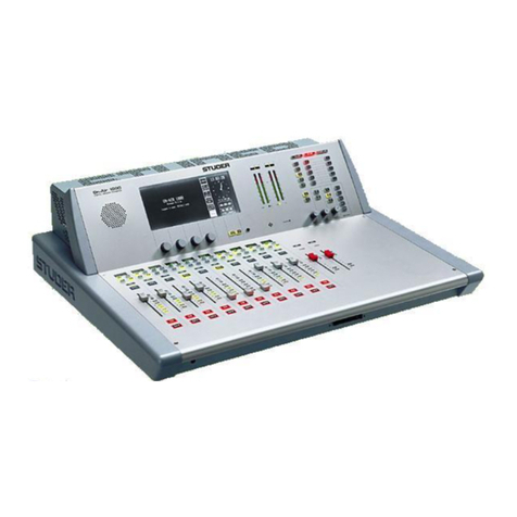
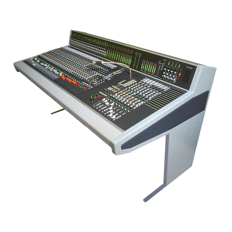
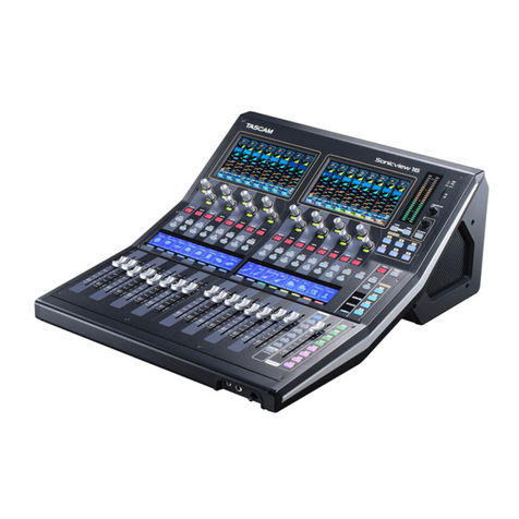
Studer Vista 5 M2 User manual

Vista 5 M2 Digital Mixing System
TFT Meters 1
Date printed: 09.06.11 SW V4.5
VISTA 5 M2, SW V4.5, DIFFERENCES AND NEW FEATURES
Please insert this document at the end of chapter 10 of your Vista 5 operating instructions folder.
Meterbridge Installation (Option)............................................................................................................................................. 3
Mechanical ............................................................................................................................................................................... 3
Electrical................................................................................................................................................................................... 4
Configuration............................................................................................................................................................................ 4
System Start.............................................................................................................................................................................. 4
TFT Level Meters........................................................................................................................................................................ 5
TFT Meter Setup ...................................................................................................................................................................... 8

Vista 5 M2 Digital Mixing System
2 TFT Meters Date printed: 09.06.11
SW V4.5

Vista 5 M2 Digital Mixing System
TFT Meters 3
Date printed: 09.06.11 SW V4.5
Meterbridge Installation (Option)
Please Note This option can only be used for Vista 5 M2 consoles, i.e. with SW versions
4.5.03 and up. If your console should not be a Vista 5 M2, it has to be electri-
cally upgraded to M2 before, please contact your distributor.
Contents of the Kit • Meterbridge(32or42faderversion,dependingonyourconsole)
• 6screwsM4
• 2Cat5linkcables(30cm/1m)
• DVIcable(1.8m)
• Power-onlinkcableDB9(0.5m)
• Thisinstallationinstructionsheet
Required Tools • 2.5mmAllenkey
• 3mmAllenkey
Mechanical
Important
!
For attaching the meterbridge to the console, you will need the assistance of
one or, even better, two additional person(s). Ask them to proceed with care
in order not to damage any surface or screen.
Switchtheconsoleoffandplaceitinsuchawaythatitsrearsidecaneasily
beaccessed.
Removeanycablingfromtheconsole’srearsidethatmightgetinyourway
during installation.
DisconnectandremovetheGCscreenfromtheconsole.Usea3mmAllen
key.Thisscreenwillnomorebeusedsinceoneofthemeterbridgescreens
isprovidedforthispurpose.
Removethe6countersunk-headscrewsattherearoftheconsole,markedin
redinthepicturebelow.Usea2.5mmAllenkey.Thesescrewswillnomore
beused.
32-fader console:
42-fader console:
VGA
SECONDARYLANPRIMARYLAN GRAPHICALCONTROLLER SCREEN
VGA
DVI
CUSTOMPANEL GPIO
COM1(RS422) COM2(RS422)
DATA(USB)
12/24V
DIN
MIDIIN MIDIOUT 1 MIDI OUT 2
OUT
(MAIN)
POWER
(MAIN)
POWER
(REDUNDANT)
100-240V~ 100-240V~ 100-240V~
(12V)
DESKLIGHT
(12V)
DESKLIGHT
(12V)
DESKLIGHT
LINE
CONTROL ROOM STUDIO A DESK MIC OUT
PROD TB INSTUDIO B
PFL
L R
LINE
L R
LINE
L R
LINE
L R
AES/EBU
L/R
AES/EBU
L/R
AES/EBU
L/R
AES/EBU AES/EBU
L/R(DIR OUT)
AES/EBU
C/LFE(DIR OUT)
AES/EBU
C/LFELFEC
LS RS
AES/EBU
LS/RS
AES/EBU
LS/RS(DIR OUT)
L R
LINE LINE
L R
LINE LINE
LINE
LINE
LINE
(DIROUT)
LINE
(DIROUT)
MONITORINSERT (AES/EBU)
GENERICI/O (AES/EBU)
MADI(TO CORE)
WCLKOUT
LOCK
TBIN
TBIN
L/R
(12V)
DESKLIGHT
f
DVI
D9p/f D9p/f
MIDIMIDIMIDI
D 37p / f
D 25p / f
D 25p / f
Withyourassistant(s),setupthemeterbridgeattheconsole’srearside.Pro-
visionallyfixitattheextremeleftandrightwithoneofthenewscrewseach
intheupperofthetwoholes.Usea3mmAllenkey.Donottightenthese
screwscompletely.Theninserttheremainingnewscrewsandtightenthem
all.

Vista 5 M2 Digital Mixing System
4 TFT Meters Date printed: 09.06.11
SW V4.5
Electrical
1. Wirethesystemaccordingtothediagrambelow.
2. Connectthemainscableattachedtothemeterbridgetothemainsoutletat
theconsole’srearside.
SCore Live
Frame
VISTA 5 M2 Desk
Rear Side
Cat5 Control Connection Desk - Core
Cat5 Control
Connection
Meterbridge
- Core
GB Ethernet Switch
Cat5 MADI Connection
Desk-Core
(CR Monitoring)
Secondary Lan Port to Meterbridge Switch
Meterbridge PC to
Meterbridge Switch
GC DVI Signal to Meterbridge
Meterbridge PC
(Bottom View)
Ext. DVI Input Power ONGC DVI Input
Power ONGC DVI Input
Ethernet EthernetUSB
Power-On Link to Meterbridge PC
Cat5 Ethernet Connection
Cat5 MADI Connection
DVI Connection
Power-On Connection
Configuration
ForcorrectoperationoftheTFTmeters,openthe D950system.ini file
and add HasTFTMeters=Yes in the [d950systeminfo] area.
System Start
Oncethisallisdone,theVista5M2canbestartedasusual,asdescribedin
thismanual.Themeterbridgewillautomaticallystartupwiththeconsole.

Vista 5 M2 Digital Mixing System
TFT Meters 5
Date printed: 09.06.11 SW V4.5
TFT Level Meters
Dependingonconsolesize,theTFTmeterbridgefeatureseitherthreeorfour
screensdedicatedtothemetering.Anadditionalscreenisusedfordisplay-
ingeithertheGCinformationofthedeskcontrolPC,themeteringPCor
anexternalDVIsignal;selectionfromthesesignalsisdonewiththe3keys
locatedjustbelowthisscreenlabeledGC,INT and EXT.
ThemeteringPC also features two USB sockets where a keyboard anda
mousemaybeconnectedwheneveritneedstobeoperatedseparately(e.g.
foraSWupdate).
Forallpossiblechanneltypesthemeteringgoeswithit–frommonoover
stereoto5.1,alwaysinthesamespace.Prioritywastohaveaslargeabar
graphmeteraspossible.Inordertobringinmoreinformation,alowerarea
isconfigurablethatenablesdisplayingdifferentoptions,dependingonthe
channeltype.Itcanbringasurroundimagevieworwhatiscalledthe‘history
diagram’ofincomingoroutgoingsignalwaveforms.Thisshowsthehistory
ofthesignalandmakesiteasytospotanomaliesintheaudiosignal,suchas
overloadsorsignalloss.
Whenfocusingonsomeimportantchannels,onemightmisswhat’sgoing
onsomewhereelse.Ifsuddenlyhearingsomethingstrange,withthehistory
featureaquicklookacrosstheconsoleissufficienttoseewhathappened,and
where.AnotheroptioninthelowerportionoftheTFTsisabusassignment
view,givinganoverviewofthechannel’scurrentbusassignment,e.g.ona
singlechannelwherebusassignmentischangedfrequently.
Thecontrolbaymeteringdiffersfromthemeterscreensonthefaderbays;it
ismainlymadetoshowoutputchannels.Forthecontrolbaymetersdifferent
viewsareavailable.Thisviewcanbeswitchedtoapredefinedmeterviewto

Vista 5 M2 Digital Mixing System
6 TFT Meters Date printed: 09.06.11
SW V4.5
seee.g.allauxiliaryoutputs–ortoallgroups,allprogrammemasters,direct
outputs,busoutputs,N–1s,matrixchannels,etc.
Inadditionthereareuserpagesassignabletowhateverisdesiredviathestrip
set-up.Therearefourconfigurableuserpages.Oneofthemhastenslotsin
onerow,thenextonehas20slotsintworows,andthenexttwohave40half-
widthslotsintworows.Soifcallinguppagefour,thereare40meters,and
theycanbevirtuallyanything.Thetwometerslotsattherightofthecontrol
bayTFTscreencontinuouslyshowPFLandCRlevels.
Theillustrationonthepreviouspageisanexampleofameterscreenwith
mono,stereoandsurroundchannels,aswellasdifferentviewsinthelower
area–suchasmeteringoftheL2channel,history,busassignmentandsur-
roundview.Furtherinformationisdisplayedaswell,suchasgainreduction
or surround signal type.
Level Meters Thelevelmeterbargraphsindicatedigitalpeakvaluesincludingheadroom
ofmono,stereo,5.1andN–1channels.ThemeterscalealwaysisindBFS
with0dBFSatthetop,withanadditionaloverloadsegmentclearlyindicating
overloads.Stereometersfeatureacorrelationmeterontopofthemeterbars,
bothonstereoinputsaswellasonstereomasterchannels.
Abovethelevelbargraphareagainreductionmetersareadded.Clippingis
displayedbyturningthewhitebargraphsection(i.e.,thesegmentsabovethe
headroomthreshold)overtored.Themetertappointcanbeselectedfrom
input,postfaderanddirectoutputlevelofthecorrespondingchannel.
Itispossibletousetheredoverloadindicatorabovethemeterstoindicatea
leveljustenteringtheconfiguredheadroom,ratherthanclipping.Thisisset
intheGC’s‘Meter/Generator’window.
Theareabelowthelargebargraphsprovidesadditionalvisualinformation,
dependingonthechanneltypeandonwhattheoperatorpreferstosee.
Whenthedeskisin‘twolayer’mode,asmallerbargraphmeteroftheL2
channel(e.g.asparemicrophone)isalwaysshown.
Furthermorethereistheoptiontodisplaytheaudiowaveformofthesignal
thathaspassedthechannel,sotheoperatorcanseethehistoryoftheaudio
backtoaconfigurabletimeofupto50seconds.Thewaveformoftheaudio-
signalnotonlygivesveryclearinformation aboutsignalloss oroverload
(whichcoloursthatpartofthewaveforminred)butalsoindicatesthechar-
acterofthesignal,asintheageofDAWsmostoperatorsareusedtointerpret
signalsbylookingattheirwaveform.Thespeedofthemeterhistoryview
canbesetintheMetering&GeneratorSettingswindow,asshownbelow.

Vista 5 M2 Digital Mixing System
TFT Meters 7
Date printed: 09.06.11 SW V4.5
Surroundchannelscomeperdefaultwithasurroundimageviewinthelower
area,offeringaspatialvisualizationofthesurroundsignal.Itallowsspotting
anomalities in a surround signal much faster than any other method.
Alternatively,abusassignviewcanbeselectedonanychannel,givinganice
overviewofthebusroutingrightbelowthebargraphmeters.Thismaynotbe
sensibleforeverychannelbutisusefulfortheoneswherethebusassignment
is changed frequently.
Control Bay ThecontrolbayTFTmeteringisofmultipleuse.TheVIEWkeystogether with
the ñ(shift) keyallowswitchingbetweendifferentviews.AllVIEWkeysare
ofthemomentary/latchingtype.
The FOLLOWkeydisplaysthemeteringthatbelongstothechannelassigned
tothedesksurface.
Then,thereareviewkeysforalldifferenttype of master channels:Aux,
Groups,programMasters,Matrix, etc., as well as output meter viewsof
multitrackandn-1/xbusses.
Moreover,therearefouruserkeysthatallowdisplayinganychoiceofchan-
nelsofthemixingconsoleonthefouruserpages.Forassignmentthereisa
pageontheGC’sStripSetupwindowthatletsassignupto10channelson
the USER 1page,upto20channelsintworowsontheUSER 2page,and
amaximumof40half-widthchannelsintworowsonboththeUSER 3 and
USER 4 pages.
The two meter slots at the right of the control bay TFT screen, however, con-
tinuously show PFL and CR levels.

Vista 5 M2 Digital Mixing System
8 TFT Meters Date printed: 09.06.11
SW V4.5
TFT Meter Setup
Strip Setup Window Ifthe‘FaderBays’or‘ControlBay’tabisactive,everychanneldisplayed
on the console surface also has a slowmeterinthestripsetupwindowthat
isaslowindicationofsignalactivityatthischannel’sinput.Colorisusedto
identifythechannel’sstatus.Abluemeterbarmeansthatthechannelhasits
faderopenandisswitchedon.Ifthemeterbarisgray,thenthechannelhasa
signalassociatedwithit,buteitherthechannelfaderisclosedorthechannel
ismuted(off).Ifthemeterbarisred,thechannelcurrentlyisinoverload
status.

Vista 5 M2 Digital Mixing System
TFT Meters 9
Date printed: 09.06.11 SW V4.5
Fader Bay Meters ThedefaultassignmentoftheTFTmeterstothefaderchannelstripsis1:1.
Thismaybemodifiedbythesystemadministratoronly;ifnotloggedinas
systemadministrator,the‘FaderBayMeters’tabisnotdisplayed,andmeter
assignmentisisrestrictedtothecontrolbay.
Assignmentisdoneinthestripsetup window.First,clickthe‘FaderBay
Meters’tab.Thewindowchangestotheviewshownbelow.Enteringchannels
isdonewiththesamemechanismasisusedfortheassignmentofchannels
tobays.
Changesinthechannelassignmentmaybeeasilyresettothedefaultsetting
byselecting‘ResettoStripAssignment’.
Lower Meter Area Thedefaultsettingsofthelowermeterareaarelabeled‘DEF’.Thesearethe
historyviewformonoandstereochannels,andthesurroundviewfor5.1
channels.
Whenright-clickingintothelowermeterarea,thedisplaymodeofthelower
partofthemetercanbeselected(‘HIST’forthehistorydisplay,‘BUS’for
busassignmentview,‘SRND’forsurroundview,and‘L2’forlayer2view).
Optionsnotavailableforaparticularchanneltypewillbegrayed-out.
Changesmadeheremayalsoberesettothedefaultsettingbyselecting‘Reset
toStripAssignment’afteraright-clickintheuppermeterarea.
Control Bay Meters Clickonthe‘ControlBayMeters’tab.Thewindowchangestotheviewshown
below.Enteringchannelsisdonewiththesamemechanismasisusedforthe
assignmentofchannelstobays.
Afterselectingoneofthe‘USER’fields,theviewcorrespondingtotheuser
keyscanbedefined.
Pleasenotethatthetwometersatthefarrightofthecontrolbayarealways
usedforPFLandCRmonitoringandcannotbeassignedtoachannel.

Vista 5 M2 Digital Mixing System
10 TFT Meters Date printed: 09.06.11
SW V4.5
Other manuals for Vista 5 M2
1
This manual suits for next models
1
Table of contents
Other Studer Music Mixer manuals
Studer
Studer Vista 5 M2 User manual
Studer
Studer Compact InfinityCore 300 User manual
Studer
Studer OnAir 500 Modulo User manual
Studer
Studer OnAir 1500 User manual
Studer
Studer OnAir 2000M2 Training manual

Studer
Studer OnAir 3000 User manual
Studer
Studer D19m Operating instructions
Studer
Studer OnAir 3000 User manual
Studer
Studer OnAir 2500 User manual

Studer
Studer OnAir 3000 Operating instructions
