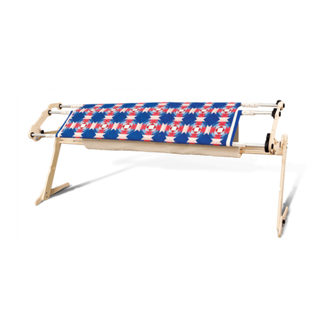
Grace Company Q-Zone Queen User manual

Assembly Instructions
Copyright December 3, 2021 V2.0 Grace Company


My Frame Details
Use this page to record information about your frame. This will be helpful if you ever need to call a
Grace Company support technician.
Frame Type: ________________________________________
Frame Conguration: Queen Crib
Date of Purchase: ____________________________________
What Machine are You Using? __________________________
Select Which Frame Accessories You Have Purchased:
Q-Zone Queen
• Table Inserts
• Start-Right Cloth Leaders
• QuiltMotion
• Pattern Perfect
• G-Series Top Plate
• Power Strip Accessory
• Speed Control
• Gracie Laser
• Sure Stitch
• Sure Stitch Elite
• Luminess Light Bar

4
X
?
1-800-264-0644
The Q-Zone Queen Quilting Frame has a One-Year limited warranty on all parts. The
Grace Company will repair or replace, at its discretion, any part with problems due to
our manufacturing or defects in materials. This warranty does not cover parts damaged
through misuse, improper storage, improper assembly, loss, natural events, and willful
destruction. Parts must be returned to the Grace Company, shipping prepaid, before
we can repair or replace them. We will promptly return the repaired/replaced part at
our expense if done within a year of the purchase date.
Warranty Information

5
My Frame Details.................................................................................................................. 3
Warranty Information............................................................................................................ 4
Table of Contents.................................................................................................................. 5
Included Parts and Tools ....................................................................................................... 6
Welcome to Your Q-Zone Queen Frame.................................................................................10
Assembly Options.......................................................................... 12
Queen Assembly ............................................................................ 13
Queen Assembly Part One .................................................................. 14
Task 1 - Set the Frame Height ..............................................................................................15
Task 2 - Install the Cross Support Tubes................................................................................18
Task 3 - Install and Align the Tracks ......................................................................................22
Task 4 - Install the Single Wheel Channel Lock.......................................................................25
Task 5 - Install the Rail Holder Brackets.................................................................................26
Queen Assembly Part Two .................................................................. 28
Task 6 - Install the Dual-Wheel Channel Lock.........................................................................29
Queen Assembly Part Three................................................................ 32
Task 7 - Install the Rails .......................................................................................................33
Task 8 - Adjust the Rails.......................................................................................................38
Task 9 - Leveling the Frame..................................................................................................40
Crib Assembly................................................................................ 44
Crib Assembly Part One...................................................................... 45
Task 1 - Set the Frame Height ..............................................................................................46
Task 2 - Install the Cross Support Tubes................................................................................49
Task 3 - Install and Align the Tracks ......................................................................................52
Task 4 - Install the Single Wheel Channel Lock.......................................................................55
Task 5 - Install the Rail Holder Brackets.................................................................................56
Crib Assembly Part Two...................................................................... 58
Task 6 - Install the Dual-Wheel Channel Lock.........................................................................59
Crib Assembly Part Three ................................................................... 62
Task 7 - Install the Rails .......................................................................................................63
Task 8 - Adjust the Rails.......................................................................................................67
Task 9 - Leveling the Frame..................................................................................................70
Part Four........................................................................................... 74
Task 10 - Attaching the Fabric...............................................................................................75
Task 11 - Using the Rails ......................................................................................................82
Table of Contents
6
Left Leg
Assembly
QZF-09-13058
See page 15, 46
Right Leg
Assembly
QZF-09-13060
See page 15, 46
Bottom
Carriage
ACC- 01-11950
See page 32, 22
Dual-Wheel
Channel Lock
ACC-09-13057
See page 32, 59
Single Wheel
Channel Lock
ACC-09-13056
See page 25, 55
SBHCS
M6 x 20 mm
HDW-03-10088
Left Rail Holder
Bracket (x2)
QZF-09-13128
See page 26, 56
Right Rail Holder
Bracket (x2)
QZF-09-13129
See page 26, 56
Included Parts and Tools
Box 1
Carriage Box
Rail Holder Bracket Box
Middle Leg
Assembly
QZF-09-13059
See page 7

7
Middle
Leg Brace (x2)
QZF-04-12060
See page 18
Corner Leg Brace
Side B (x2)
QZH-04-16326
See page 18, 49
Corner Leg Brace
Side A (x2)
QZH-04 -12031
See page 18, 49
Ratchet Cap (x2)
QZF-05-10315
See page 33, 63
Hardware Box
Bungee Clamp
Accessory (x4)
ACC-01-10261
See page 75
Included Parts and Tools (continued)
Fabri-Fast Tool
ACC-05-10417
See page 75
C-Clamp (x4)
QZF-05-10621
See page 75
Long Track (x2)
QZF-05-12057
See page 22
Fabri-Fast
Tubing (x2)
PLA-05-10408
See page 75
Reference
Card Hook
HDW-03-16369
See page 18, 49

8
Bagged Hardware
Allen Wrench
3 mm
HDW-03-10166
Allen Wrench
4 mm
HDW-03-10167
10
13
Open End Wrench
10 mm and 13 mm
HDW-03-10743
17
14
Open End Wrench
14 mm and 17 mm
HDW-03-12068
SBHCS
M6 x 16 mm (x4)
for task 5
HDW-03-10974
Connector Bolt
M6 x 10 mm (x36)
for task 2
HDW-03-10953
Connector Bolt
M6 x 10 mm (x16)
for task 3
HDW-03-10953
Included Parts and Tools (continued)

9
Ratcheting Rail
Section (x2)
QZF-09-13067
See page 33, 63
Floating Rail
Section (x2)
QZF-09-13068
See page 33, 63
Rail Coupler (x2)
QZF-09-13131
See page 33
Long Track
Support (x2)
QZF-04-12058
See page 22, 52
Short Track
Support (x4)
QZF-04-12059
See page 22
Frame Cross
Support Tube (x4)
QZF-04-12061
See page 18, 49
Short Track (x2)
QZF-05-12067
See page 52
Box 2
Included Parts and Tools (continued)

10
We are pleased to introduce you to the newest part of your quilting setup. This frame has been
especially designed to help quilters like you have the tools available to create quality projects.
This manual is broken into four sections (or parts). Notications at the end each of each section will
direct you to switch to your machine manual or QuiltMotion manual for instructions on assembling
those products. This creates a streamlined process of building a complete quilting setup in the most
ecient way. Use the following owchart to guide you in navigating multiple manuals. If you are not
using one of the products in the owchart, just move to the next item in the chart.
Thank you again for choosing us to help your quilting projects. We look forward to working with you.
- The Grace Company
Start Here: Frame Manual: Part One
• Assemble the frame’s legs, table, and sides.
• Install the channel lock onto the bottom
carriage.
• Align your tracks.
Quilting Machine Manual: Part One
• Install the lower encoder onto the bottom
carriage.
QuiltMotion Manual: Part One
• Prepare the bottom carriage.
• Install the long belt across the frame.
Quilting Machine Manual: Part Two
• Install your machine’s wheels.
• Align your wheels.
QuiltMotion Manual: Part Two
• Install the short belt.
• Tension the short belt.
Welcome to Your Q-Zone Queen Frame

11
Frame Manual: Part Two
• Install the channel lock on the machine or
top plate.
• Prepare the top plate and home sewing
machine.
• Place the machine or top plate on the frame.
Quilting Machine Manual: Part Three
• Install the wheel covers, display, handles,
thread mast.
• Install the upper encoder.
Frame Manual: Part Three
• Install the rails and fabric bungees.
• Position and adjust the rails.
• Adjust the carriage stop.
• Level the frame.
QuiltMotion Manual: Part Three
• Install the tablet bracket.
• Plug in QuiltMotion.
• Use the quilting modes and settings in the
display.
• Maintain the machine and perform repairs.
Quilting Machine Manual: Part Four
Frame Manual: Part Four
• Install the velcro tape
• Install the cloth leaders
• Attach the fabric

12
Queen Assembly
See page 13
Assembly Options
Crib Assembly
See page 44
Fits quilt tops up to 76 inches wide
Fits quilt tops up to 26 inches wide

13
Queen Assembly

14
Queen Assembly
Part One
Part One
Progress Checkpoint
Complete Part One of these instructions before assembling your quilting
machine or any accessories. The beginning of each Part will contain a
progress checkpoint, helping make sure you accomplish all of the tasks
necessary to complete your quilting setup in the most convenient order.
Queen Assembly Part One

15
Task 1 - Set the Frame Height
Queen Assembly Part One
Parts & Tools Needed:
Left Leg
Assembly
Right Leg
Assembly
Middle Leg
Assembly
Allen Wrench
4 mm
10
13
Open End Wrench
10 mm and 13 mm
1. Begin with the left leg. With the 4 mm Allen wrench and the 10 mm open end wrench, remove
the height screws, washers, and nuts.
Height Screw
(x2) Washers (x2)
1
Tape Measure
(not included)
Nuts (x2)
Instructions
The frame height is important for comfortable prolonged use. Ideally, when fully assembled the
handlebars on your machine or top plate will be around elbow height. Take the following steps to set
your frame height:

16
1. Use the 4 mm Allen wrench to loosen, but not remove, the two M6 connector bolts.
M6 Connector Bolts (x2)
Hole
Number
Elbow to Floor
1 37 1/2 Inches
238 1/2 Inches
3 39 1/2 Inches
4 40 1/2 Inches
5 41 1/2 Inches
642 1/2 Inches
7 43 1/2 Inches
844 1/2 Inches
9 45 1/2 Inches
10 46 1/2 Inches
Note: Height will vary
slightly after adjusting
leveling feet in Task 9 on
page 40.
2
Hold your arm at a 90 degree angle. Use a tape measure to measure the distance from your
elbow to the oor.
3
Task 1 - Set the Frame Height (continued)
Queen Assembly Part One

17
Use the 4 mm Allen wrench to re tighten the M6 connector bolts.
4
Repeat steps 1-4 for the middle leg and the right leg, making sure to set them to the same
height as the left leg.
5
Task 1 - Set the Frame Height (continued)
Set your frame leg to the corresponding hole and secure in place with the screws, washers, nuts,
4 mm Allen wrench, and 10 mm open end wrench.
6
Queen Assembly Part One

18
Task 2 - Install the Cross Support Tubes
Parts & Tools Needed:
Middle
Leg Brace (x2)
Corner Leg Brace
Side B (x2)
Corner Leg Brace
Side A (x2)
Frame Cross
Support Tube (x4)
Connector Bolt
M6 x 10 mm (x36)
Instructions
Take the following steps to attach the leg braces to the legs and install the frame cross support tubes:
1. Begin with the right leg. Use the 4 mm Allen
wrench and two M6 x 10 mm connector
bolts to loosely attach a corner brace
side A to the front of the leg.
1
Allen Wrench
4 mm
1. Loosely connect the reference card hook
to the side of the corner bracket with an
M6 x 10 mm connector bolt.
2
Connector Bolt
M6 x 10 mm
Queen Assembly Part One
Reference Card
Hook
Connector Bolt
M6 x 10 mm (x2)
Corner Brace A
Reference
Card Hook

19
1. Take the left leg and use the 4 mm Allen
wrench and two M6 x 10 mm connector
bolts to loosely attach a corner brace
side B to the front of the leg.
1. Use the 4 mm Allen wrench and loosely
attach a corner brace side B to the
back of the right leg with four M6 x 10
connector bolts.
1. Loosely screw in two more M6 x 10 mm
connector bolts in the brace holes on the
side of the leg.
5
1. Use the 4 mm Allen wrench and loosely
attach a corner brace side A to the
back of the left leg with four M6 x 10
connector bolts.
6
7
Connector Bolt
M6 x 10 mm (x4)
Corner Brace B
Connector Bolt
M6 x 10 mm (x2)
Corner Brace B
Connector Bolt
M6 x 10 mm (x2)
Corner Brace A
Connector Bolt
M6 x 10 mm (x4)
Middle Leg Brace (x2)
Connector Bolt
M6 x 10 mm (x4)
Task 2 - Install the Cross Support Tubes (continued)
Queen Assembly Part One
1. Loosely attach the two middle leg braces
to the middle leg using four M6 x 10 mm
connector bolts and the 4 mm Allen
wrench.
8
1. Loosely attach a second M6 x 10
connector bolt to the side of the corner
brace.
3
Connector Bolt
M6 x 10 mm
4

20
1. Place the end of a cross support tube so that it rests on the shelf of the corner bracket on
the front of the left leg. Loosely attach it with two M6 x 10 connector bolts and the 4 mm Allen
wrench.
9
Cross Support Tube
Shelf
1. Loosely attach the other end of the cross support tube to the front brace on the middle leg
using two M6 x 10 mm connector bolts and the 4 mm Allen wrench.
1. Repeat steps 8-9 for the rear cross support tube.
11
Connector Bolt
M6 x 10 mm (x2)
Task 2 - Install the Cross Support Tubes (continued)
Connector Bolt
M6 x 10 mm (x2)
Queen Assembly Part One
10
Table of contents
Other Grace Company Sewing Machine manuals

Grace Company
Grace Company Q'nique 16X Manual User manual

Grace Company
Grace Company QuiltMotion User manual

Grace Company
Grace Company Q'nique 16X ELITE User manual

Grace Company
Grace Company Sure Stitch User manual

Grace Company
Grace Company Q'nique 21 User manual

Grace Company
Grace Company Q'nique 19 X User manual

Grace Company
Grace Company NM-EZ3 User manual

Grace Company
Grace Company G Series User manual

Grace Company
Grace Company Cuite Quick setup guide