Grace Company Q'nique 21 User manual

Service Manual
21

Bobbin Winder ............................................................................................................................ 1
Display Board Box ....................................................................................................................... 2
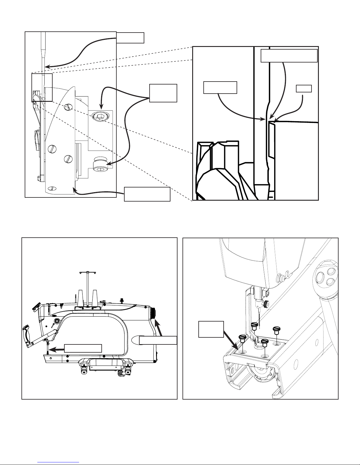
Needle Bar Height ....................................................................................................................... 3
Hopping Foot Height.................................................................................................................... 4
Hook Holder ............................................................................................................................... 5
Needle Plate ............................................................................................................................... 6
Handle Bars ................................................................................................................................ 6
Timing........................................................................................................................................ 7
Thread Tensioner ........................................................................................................................ 9
Adjusting Thread Tensioner.........................................................................................................10
Extrusions Cover ........................................................................................................................11
Front Cover................................................................................................................................12
Needle Rod Holders....................................................................................................................13
Upper Shaft ...............................................................................................................................14
Pulley and Optical Encoding Wheel ..............................................................................................15
LED Assembly ............................................................................................................................15
Lower Shaft ...............................................................................................................................16
Bushing Block ............................................................................................................................17
Bushing Block ............................................................................................................................18
Main Board ................................................................................................................................19
Power Supply.............................................................................................................................20
Motor Driver Board ....................................................................................................................21
Grounding Wire..........................................................................................................................21
Idler Pulley Tension ....................................................................................................................22
MCU Board Update.....................................................................................................................23
Motor Driver Board.....................................................................................................................26
Motor Driver Board Plugs ............................................................................................................26
Self Calibration Instructions ........................................................................................................27
Window Offset Adjustment Instructions .......................................................................................28
Encoder Test..............................................................................................................................29
Button Test ................................................................................................................................29
Sensor Test................................................................................................................................30
i
|Table of Contents Q’nique 21: Service Manual

Tools Needed:
3. If thread winds mostly on the bottom of the
bobbin, the Tension Disc Post will need to be
heightened by twisting it counter clockwise and
retightening the hex nut.
2. If thread winds mostly on the top of the
bobbin, the Tension Disc Post will need to be
heightened by twisting the Tension Disc Post
clockwise and retightening the hex nut.
1. Adjust the Bobbin Winder Cam to be centered to the Bobbin without touching it by loosening the
Set Screw with the 1.5 mm Allen Wrench, adjusting the Cam, and retightening the Set Screw. If
thread winds mostly on the top of the bobbin, the Tension Discs Post will need to be lowered by
twisting the Tension Disc Post clockwise and retightening the hex nut.
9mm Crescent Wrench
1.5mm Allen Wrench
Set
Screw Tension
Disc Post
|Bobbin Winder Q’nique 21: Service Manual
1

A A
B B
2
2
1
1
DO NOT SCALE DRAWING
Sewing Machine Q'nique 21
SHEET 1 OF 1
UNLESS OTHERWISE SPECIFIED:
SCALE: 1:12
WEIGHT:
REV
DWG. NO.
A
SIZE
TITLE:
NAME
DATE
COMMENTS:
Q.A.
MFG APPR.
ENG APPR.
CHECKED
DRAWN
FINISH
MATERIAL
INTERPRET GEOMETRIC
TOLERANCING PER:
DIMENSIONS ARE IN INCHES
TOLERANCES:
FRACTIONAL
ANGULAR: MACH
BEND
TWO PLACE DECIMAL
THREE PLACE DECIMAL
APPLICATION
USED ON
NEXT ASSY
PROPRIETARY AND CONFIDENTIAL
THE INFORMATION CONTAINED IN THIS
DRAWING IS THE SOLE PROPERTY OF
<INSERT COMPANY NAME HERE>. ANY
REPRODUCTION IN PART OR AS A WHOLE
WITHOUT THE WRITTEN PERMISSION OF
<INSERT COMPANY NAME HERE> IS
PROHIBITED.
1. Press the Tab inward and pull the Screen
Assembly up and unplug the LCD Cable.
3. Pull the Display Board Box up and out.
2. Remove the (2) M5 x 16mm SBHCS holding the
Display Board Box.
4. Unplug the Handle Cables and Display Cable
and remove.
Tools Needed:
3mm Allen Wrench
Tab
Screen
Assembly M5 x 16mm
SBHCS
Display
Board Box
Display
Board Box
Display
Board Box
Display
Board Box
Display
Cable
Handle
Cables (2)
Screen
Assembly
|Display Board Box Q’nique 21: Service Manual
2

1. Rotate the hand wheel in the back of the
machine until the Needle Bar is in the lowest
position. Loosen screw inside sewing machine
head using a flat head screw driver.
2. Place the Needle Bar Height Spacer into the
Bobbin Case area.
3. Using a Needle Bar Height Spacer bring the
Needle Bar down till the tip of the Needle is
resting on the flat surface of the Needle Bar
Height Spacer.
4. Tighten the screw inside the head of your
machine with a flat head screw driver, make
sure the Needle Bar is facing forward so the
thread guide is in the front of your machine.
Adjust Needle
Bar height with a
Flat Head Screw
Driver here.
*Note: Display Board Box may
have to be removed to access.
Thread Guide
faces front
of machine
Needle
Bar Height
Spacer
Tighten
Screw inside
this hole
Height
Spacer
Flat Spot Tip of
Needle
Tools Needed:
Flat Head Screwdriver
Needle Bar Height Spacer
|Needle Bar Height Q’nique 21: Service Manual
3

1. Attach your Hopping Foot to the press bar
using a M3 Socket Head Screw (don’t tighten
during this step) in either of the configurations
shown.
2. Using the Hand Wheel in the back of your
machine, rotate your machine until the Needle
Bar is in the lowest position.
3. Using the hole in the Needle Plate, align the
Hopping Foot so that it is centered.
4. Place 2-6 sheets of paper under the foot and
lower the Hopping Foot to the top of the
surface depending on the thickness of your
project.
5. Tighten the M3 socket head screw using the 3
mm Allen wrench.
.5mm Gap
Gauge
M3 Socket
Head Screw
Tools Needed:
3mm Allen Wrench Press Bar
M3 Socket
Head Screw
Hopping
Foot
Needle Plate
Needle Bar
Hand Wheel
*Note: Do not over tighten, this will
cause sewing machine to bind.
|Hopping Foot Height Q’nique 21: Service Manual
4

1. Remove the Needle Plate.
2. Rotate your Hook Assembly so that the
positioning guide is at the highest point during
rotation.
3. Attach your Hook Holder to your sewing
machine with a M5 X 10mm FHCS (don’t
tighten the screw during this step) with the
Hook Holder’s finger in the middle of the Hook
Assembly’s positioning guide.
4. Slide your Hook Holder away from the Hook
Assembly so there is about a 0.75mm gap
between the Hook Holder and the Hook
Assembly, and tighten the M5 X 10mm FHCS.
Tools Needed:
3mm Allen Wrench
Flat Head Screwdriver
Needle
Plate
Hook
Holder
M5 x 10mm
FHCS
|Hook Holder Q’nique 21: Service Manual
Hook Assembly
0.75mm Gap
between Hook
Holder and Hook
Assembly
Hook Assembly
Positioning
Guide
Hook Assembly
Positioning
Guide
5
Hook Holder
It’s hard to measure
so just make it so
tip of Hook Holder is
ush with Positioning
Guide Finger

Tools Needed:
Tools Needed:
Flat Head Screwdriver
5mm Allen Wrench
4mm Allen Wrench
1. Attach your Needle Plate using (4) Needle Plate
Screws, don’t tighten the screws during this
step.
2. Rotate Hand Wheel until the Needle is in the
lowest position. Move the Needle Plate until it
is centered around the Needle and tighten all
(4) Needle Plate Screws.
1. Using the 4mm Allen Wrench, remove the (4)
Screws from the Handle Plate. Remove the
Handle Plate and the Handle Bars
Needle
Plate
Needle Plate
Screws (4)
Needle in
Lowest
Position
Set
Screw
Handle
Plate
6
1. Adjust the Handles up and down by tightening
and loosening the Set Screw on the back of the
Handle Plate using the 5mm Allen Wrench.
Handle
Plate
Handle
Bars
Handle
Bars
M6 x 16mm
Socket FCHS (4)
|Needle Plate Q’nique 21: Service Manual
Handle Bars
To Remove: To Adjust:

Needle Bar
Hand Wheel
1. Loosen all 3 Hook Assembly Set Screws with a
2mm Allen Wrench by inserting the wrench into
the Timing Hole when each Set Screw aligns
with the hole.
2. Rotate the hand wheel clockwise from the front
of the machine so needle is rising out of the
Hook Assembly.
Tools Needed:
2mm Allen Wrench
Timing Spacer
Flat Head Screwdriver
4. Bring the Needle so it rests on the top of the
Needle Bar Height Spacer, so the groove in the
needle aligns in the middle of the hook on the
Hook Assembly.
Timing
Hole
Needle
Bar Height
Spacer
Flat Side
Flat Side
7
3. Place the Needle Bar Height Spacer into the
Bobbin Case area and twist so that flat side is
vertical.
|Timing Q’nique 21: Service Manual
Tip Of
Needle
A timing tutorial is available on
our website at:
http://www.qniquequilter.com/
videos/tutorials/

Needle Bar
Hand Wheel
6. Rotate the hand wheel a full rotation. If the
needle hits the Hook Assembly anywhere,
the needle will bend or there will be a clicking
noise. Adjust the needle height closer or
farther off from the hook.
5. The Needle should be as close as possible to the Hook Assembly without touching, roughly between
0.02mm and 0.075mm. Tighten the Set Screw which is currently aligned with the Timing Hole on
the left side of the machine.
Needle
Plate
7. Tighten the two remaining set screws and
reattach the Needle Plate.
Scarf
Hook Assembly
Needle
Set
Screws
Hook
8
0.02-0.75mm Gap

1. Loosen the M5 X 8mm Set Screw to remove
the Thread Tension Assembly.
3. Tighten the M5 X 8mm Set Screw in the sewing
machine body to tighten the Thread Tension
Assembly into place.
2. Press the Thread Tension Assembly into the
sewing machine body until it bottoms out.
Orient the Thread Tension Assembly so that the
check spring is Vertical.
Tools Needed:
2.5mm Allen Wrench
Thread
Tension
Assembly
Thread
Tension
Assembly
Check
Spring
M5 x 8mm
Set Screw
M5 x 8mm
Set Screw
|Thread Tensioner Q’nique 21: Service Manual
9

1. Loosen the Tension Assembly by turning the
Tension Knob counterclockwise until the Tension
Knob is flush with the end of the Check Spring
Screw
2. Slowly loosen the Check Spring Screw with
a screwdriver counterclockwise until the Check
Spring is at 45 degrees from vertical.
A A
B B
2
2
1
1
DO NOT SCALE DRAWING
Sewing Machine Q'nique 21
SHEET 1 OF 1
UNLESS OTHERWISE SPECIFIED:
SCALE: 1:12
WEIGHT:
REV
DWG. NO.
A
SIZE
TITLE:
NAME
DATE
COMMENTS:
Q.A.
MFG APPR.
ENG APPR.
CHECKED
DRAWN
FINISH
MATERIAL
INTERPRET GEOMETRIC
TOLERANCING PER:
DIMENSIONS ARE IN INCHES
TOLERANCES:
FRACTIONAL
ANGULAR: MACH
BEND
TWO PLACE DECIMAL
THREE PLACE DECIMAL
APPLICATION
USED ON
NEXT ASSY
PROPRIETARY AND CONFIDENTIAL
THE INFORMATION CONTAINED IN THIS
DRAWING IS THE SOLE PROPERTY OF
<INSERT COMPANY NAME HERE>. ANY
REPRODUCTION IN PART OR AS A WHOLE
WITHOUT THE WRITTEN PERMISSION OF
<INSERT COMPANY NAME HERE> IS
PROHIBITED.
3. Tighten the Check Spring screw until the Check
Spring is back to vertical. Then continue rotation
for an additional 1/4 turn.
4. Tighten Tension Knob until the thread is
centered in the fabric layers.
Note: If you are breaking thread tighten Check
Spring tension by turning Check Spring Screw.
If showing top thread on bottom you need to add
more tension by turning the Tension Knob clockwise.
If you are bunching up in corners loosen Check
Spring by turning Check Spring Screw.
If showing bottom thread on top you
need to loosen the tension by turning the
Tension Knob counterclockwise.
A A
B B
2
2
1
1
DO NOT SCALE DRAWING
Sewing Machine Q'nique 21
SHEET 1 OF 1
UNLESS OTHERWISE SPECIFIED:
SCALE: 1:12
WEIGHT:
REV
DWG. NO.
A
SIZE
TITLE:
NAME
DATE
COMMENTS:
Q.A.
MFG APPR.
ENG APPR.
CHECKED
DRAWN
FINISH
MATERIAL
INTERPRET GEOMETRIC
TOLERANCING PER:
DIMENSIONS ARE IN INCHES
TOLERANCES:
FRACTIONAL
ANGULAR: MACH
BEND
TWO PLACE DECIMAL
THREE PLACE DECIMAL
APPLICATION
USED ON
NEXT ASSY
PROPRIETARY AND CONFIDENTIAL
THE INFORMATION CONTAINED IN THIS
DRAWING IS THE SOLE PROPERTY OF
<INSERT COMPANY NAME HERE>. ANY
REPRODUCTION IN PART OR AS A WHOLE
WITHOUT THE WRITTEN PERMISSION OF
<INSERT COMPANY NAME HERE> IS
PROHIBITED.
Check
Spring
Tools Needed:
Flat Head Screwdriver
Tension
Knob
Check
Spring
Check Spring
Screw Screwdriver
10
|Adjusting Thread Tensioner Q’nique 21: Service Manual

Tools Needed:
4mm Allen Wrench
1. Remove the (2) bolts on the side of the
Extrusion Cover.
2. Remove Cover.
3. Repeat for Left side if needed.
M6 x 10mm
SBHCS
Extrusions
Cover
|Extrusions Cover Q’nique 21: Service Manual
11

4mm Allen Wrench
Tools Needed:
1. Remove Extrusions Cover and Handles, then
remove (1) M6 x 10mm SBHCS and (1) M8 x
12mm SHSS attaching the Machine Body to the
extrusions.
2. Remove (7) M6 x 25mm SBHCS and (1) M6 x
60mm SBHCS.
3. Remove Cover.
M6 x 10mm
SBHCS
M8 x 12mm
SHSS
M6 x 25mm
SBHCS (6)
Sewing
Machine
Cover
M6 x 60mm
SBHCS
1
2
3
4
5
6
7
8
12
4. When re-installing front cover tighten the screws in the order shown above.
|Front Cover Q’nique 21: Service Manual

Retaining Ring
Slide Plate
Slide Block
M4 x 10mm
SBHCS
Stop Collar
Press Bar
Spring
M5 x 10mm
SBHCS (2)
Press Bar Link
Connecting
Link V2
Press
Bar Slide
Attachment
Tools Needed:
2.5mm Allen Wrench
3mm Allen Wrench
10mm Open End Wrench
1. Slightly loosen M4 x 10mm SBHCS allowing Stop Collar to be loose from the Needle Bar.
2. Loosen Connecting Link V2 from Bushing Bearing. Remove Slide Plate from Sewing
Machine using 3mm Allen Wrench to remove (2) M5 x 10mm SBHCS.
3. Remove Pressure Bar Assembly from Sewing Machine.
|Needle Rod Holders Q’nique 21: Service Manual
13

3-M4 X 4 Set Screw
1-Thread Take Up
Crank Assembly 1-Counter Weight
1-Top Bearing
1-Crank Screw
Orientation
1-Crank Screw
Securing
2-Flat Set
Screw
1-Top Shaft Pulley
Note: D-Key needs to be set in
this orientation
1-Top
Bearing
1-Thread Take Up
Crank Pin
3-M4 X 4
Set Screw
1-Thread Take Up
Lever Spiring
1-Top
Bearing
3-M4 X 4 Set Screw
3-M4 X 4 Set
Screw
1-Secondary Counter Weight
3-M5 X 8 Set
Screw
1-Main Shaft
1-Hopping Foot
Eccentric Cam
Assembly
1-Optical Encoder
Assembly
Tools Needed:
2.5mm Allen Wrench
3mm Allen Wrench
Thread Take
Up Lever
Clamp
Thread Take
Up Lever
Clamp Right
Main Shaft
Bushing
Clamp (3)
M5 x 10mm
SBHCS (6)
M4 x 8mm
SBHCS (4)
1. Remove (6) M5 x 10mm SBHCS and (3) Main Shaft Bushing Clamps using the 3mm Allen Wrench.
2. Remove Upper Shaft out of the Body.
3. Top Shaft Assembly.
|Upper Shaft Q’nique 21: Service Manual
14
A A
B B
2
2
1
1
DO NOT SCALE DRAWING
Mechanics
SHEET 1 OF 1
UNLESS OTHERWISE SPECIFIED:
SCALE: 1:12
WEIGHT:
REV
DWG. NO.
A
SIZE
TITLE:
NAME
DATE
COMMENTS:
Q.A.
MFG APPR.
ENG APPR.
CHECKED
DRAWN
FINISH
MATERIAL
INTERPRET GEOMETRIC
TOLERANCING PER:
DIMENSIONS ARE IN INCHES
TOLERANCES:
FRACTIONAL
ANGULAR: MACH
BEND
TWO PLACE DECIMAL
THREE PLACE DECIMAL
APPLICATION
USED ON
NEXT ASSY
PROPRIETARY AND CONFIDENTIAL
THE INFORMATION CONTAINED IN THIS
DRAWING IS THE SOLE PROPERTY OF
<INSERT COMPANY NAME HERE>. ANY
REPRODUCTION IN PART OR AS A WHOLE
WITHOUT THE WRITTEN PERMISSION OF
<INSERT COMPANY NAME HERE> IS
PROHIBITED.

4mm Allen Wrench
Tools Needed:
LED Assembly
Speed Sensor Cable
M6 x 15mm
SBHCS
Note: This
side faces
up when
plugging in
handles.
Optical Encoding Board
1. Remove (2) M3 x 6mm SBHCS. 2. Unplug (2) Handle Plugs and (1) LED Plug.
Tools Needed:
4mm Allen Wrench
3mm Allen Wrench
2mm Allen Wrench
M3 x 6mm
SBHCS (2)
LED Plug
Handle
Plugs (2)
1. Install the Optical Encoding Board using (2) M6
x 15mm SBHCS and plug in the Speed Sensor
Cable.
1. Top Shaft Pulley needs to be 7mm from Bearing
Collar.
2. Optical Encoding Wheel needs to be centered
in the Emitting Sensor on the Optical Encoding
Board.
7mm Centered
|
Pulley and Optical
Encoding Wheel Q’nique 21: Service Manual
15

1. Remove Pulley Axle, Pulley, and M6 Nut
2. Remove (2) Lower Shaft Bushing Clamp Front and (1) Lower Shaft Bushing Clamp and (8) M5 x
10mm SBHCS.
3. Remove Lower Shaft.
Tools Needed:
10mm Open End Wrench
Flat Head Screw Driver
3mm Allen Wrench
M5 x 10mm
SBHCS (8)
M6 Nut
Pulley
Lower Shaft
Bushing Clamp
Front (2)
Lower Shaft
M4 x 4mm
Hex Socket
Set Screw (12)
Bottom
16 Tooth
t5 Pulley
Bearing
12mm
Shaft (3)
Lower Shaft
Hook
Assembly
Hook
Assembly Set
Screw (3)
Lower Shaft
Bushing
Clamp
Pulley Axle
4. Lower Shaft Exploded View.
|Lower Shaft Q’nique 21: Service Manual
16

M4 x 8mm
SBHCS (2)
M6 x
10mm Set
Screw (2)
Bushing
Block
Needle Bar
Needle Bar
Thread
Guide
M3 Thumb
Screw
Needle
M6 x 16mm
SBHCS (3)
Bushing Block
Adjustment
Plate
1. Attach the Bushing Block Adjustment Plate to the body with M4 x 8mm SBHCS. Leave the screws
loose. Slide the Bushing Block over the Adjustment Plate and thread the M6 x 16mm SBHCS. Leave
the screws loose.
2. Thread the M6 x 10mm Set Screws into the Bushing Block.
4. Attach the Needle Bar Thread Guide and secure
a Needle in place using the M3 Thumb Screw.
3. Slide the Needle Bar through the top of the
machine and through the bushing block.
Tools Needed:
10mm Open End Wrench
Flat Head Screwdriver
3mm Allen Wrench
2.5mm Allen Wrench
|Bushing Block Q’nique 21: Service Manual
17

M4 x 8mm
SBHCS (2)
M5 x 8mm
Set Screws
(2)
M6 x 10mm
Set Screws
(2)
Tighten
the lower
screw first
Bushing Block
Adjustment
Plate
Press Bar
Guide
M4 x 8mm
SBHCS (2)
7. Use the M6 x 10mm Set Screws to adjust the
Bushing Block in and out so that the Needle is
in line with the hole on the Needle Plate.
6. Slide the Bushing Block Adjustment Plate so
that the needle is in line with the hole on
the Needle Plate then tighten the M4 x 8mm
SBHCS to lock it in place.
5. Attach the Press Bar Guide using (2) M4 x 8mm
SBHCS.
8. Tighten the M6 x 16mm SBHCS on the back
of the machine. Tighten the lower screw first,
then tighten the two upper screws.
18
Table of contents
Other Grace Company Sewing Machine manuals

Grace Company
Grace Company QuiltMotion User manual

Grace Company
Grace Company Q'nique 16X ELITE User manual

Grace Company
Grace Company Q'nique 16X Manual User manual

Grace Company
Grace Company Q'nique 19 X User manual

Grace Company
Grace Company Q-Zone Queen User manual

Grace Company
Grace Company NM-EZ3 User manual

Grace Company
Grace Company G Series User manual

Grace Company
Grace Company Cuite Quick setup guide

Grace Company
Grace Company Sure Stitch User manual