ii
Table of Contents......................................................................................................................ii
Warranty ..................................................................................................................................iii
Parts Lists
Box 1......................................................................................................................................iv
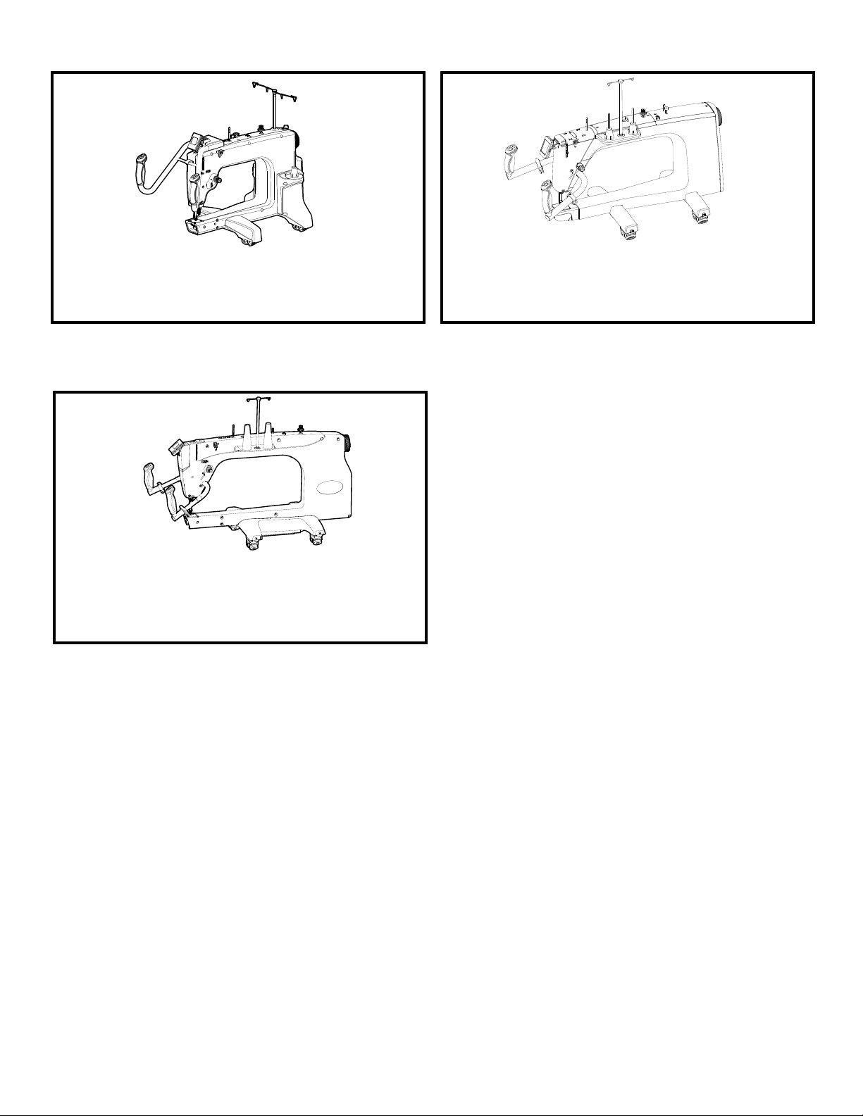
Choose your Machine
Choose your Machine ................................................................................................................v
15” Machine Assembly Instructions
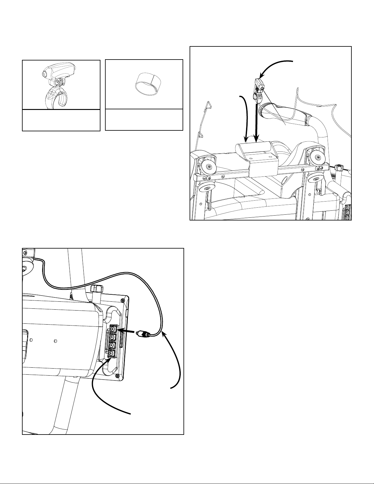
Step 1: Laser Bracket Installation .............................................................................................. 1
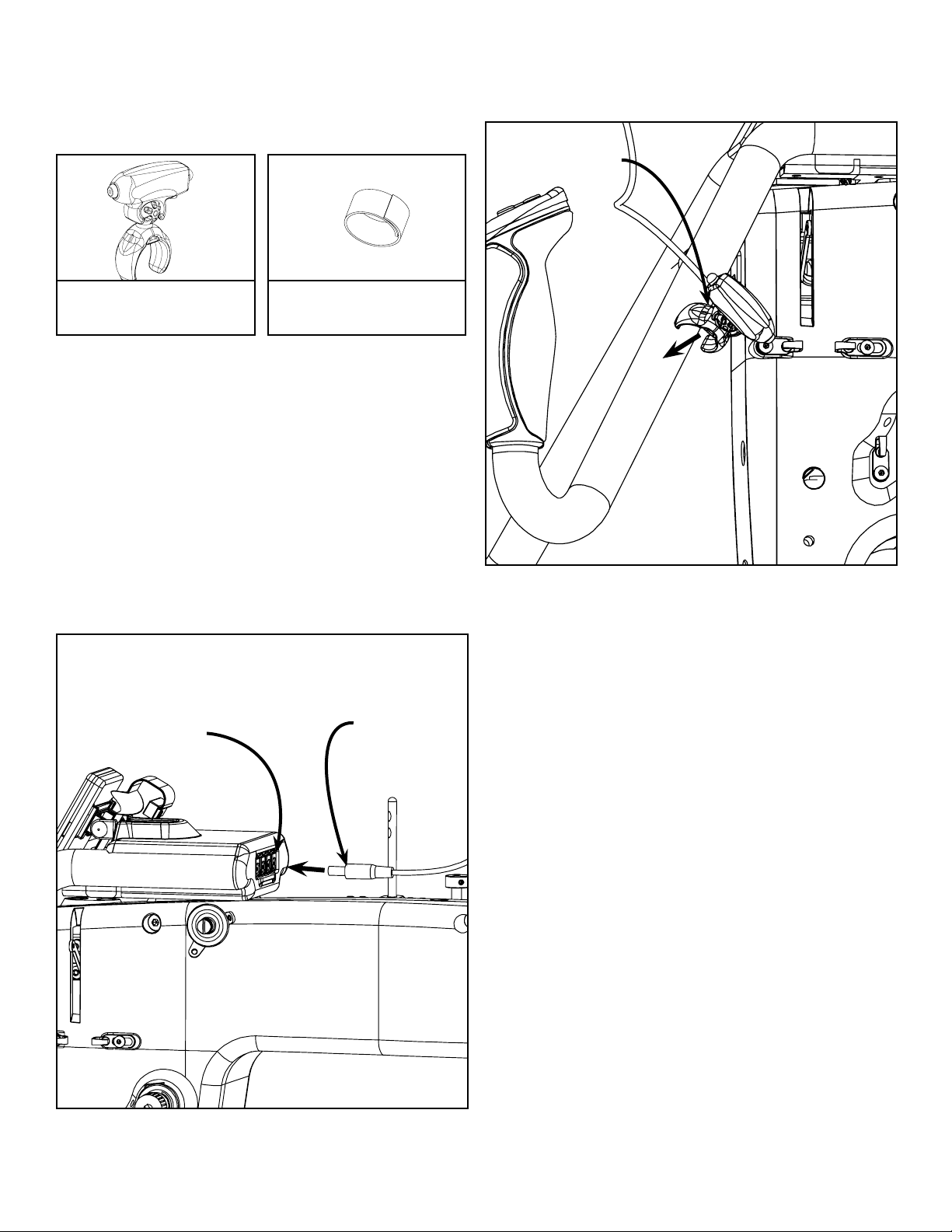
Step 2: Laser Installation - Rear Handlebars............................................................................... 2
Step 2: Laser Installation - Front Handlebars .............................................................................. 3
19” Machine Assembly Instructions
Step 1: Laser Bracket Installation .............................................................................................. 4
Step 2: Laser Installation - Rear Handlebars............................................................................... 5
Step 2: Laser Installation - Front Handlebars .............................................................................. 6
21” Machine Assembly Instructions
Step 1: Laser Bracket Installation .............................................................................................. 7
Step 2: Laser Installation - Rear Handlebars............................................................................... 8
Step 2: Laser Installation - Front Handlebars .............................................................................. 9
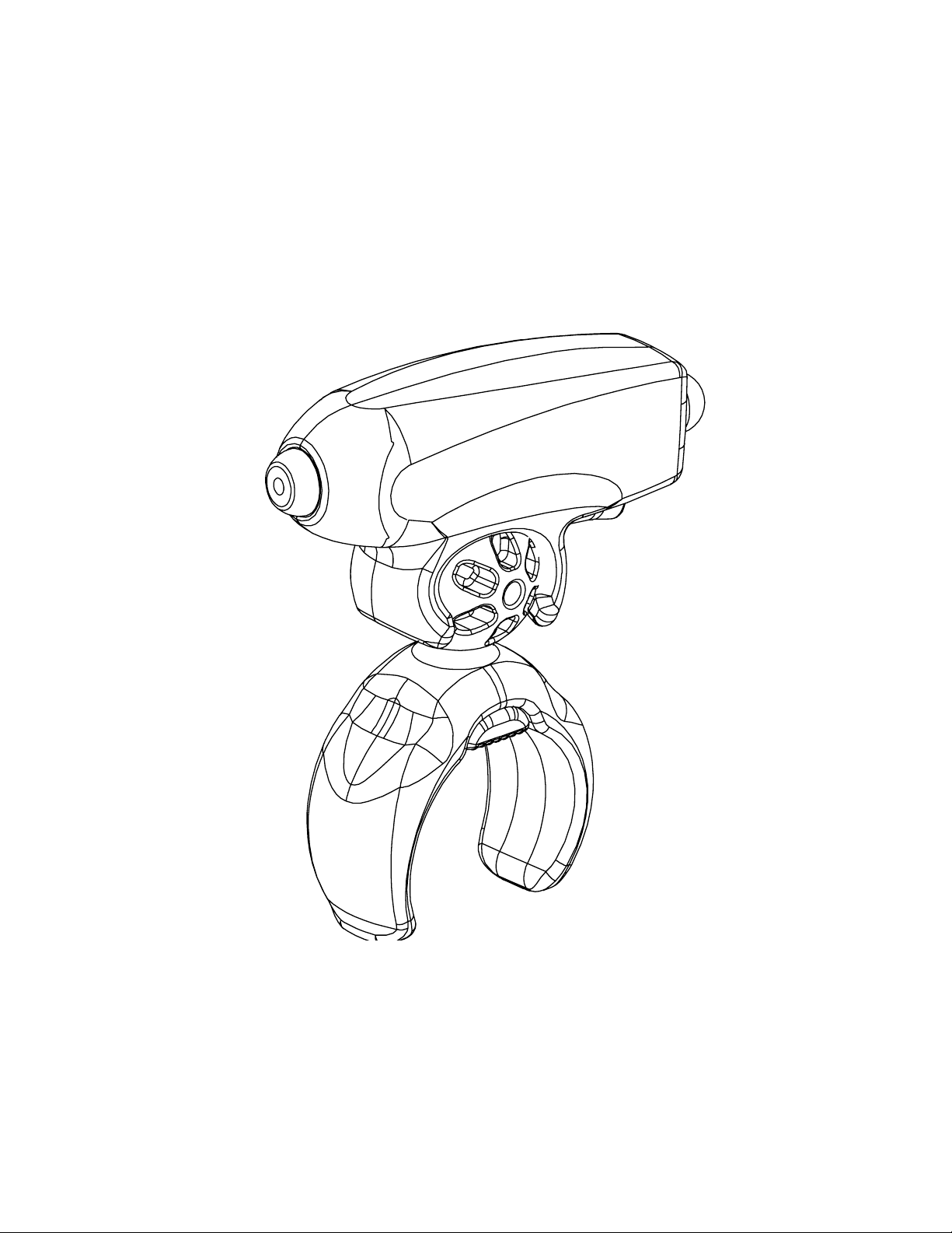
|Table of Contents Qnique Laser Stylus