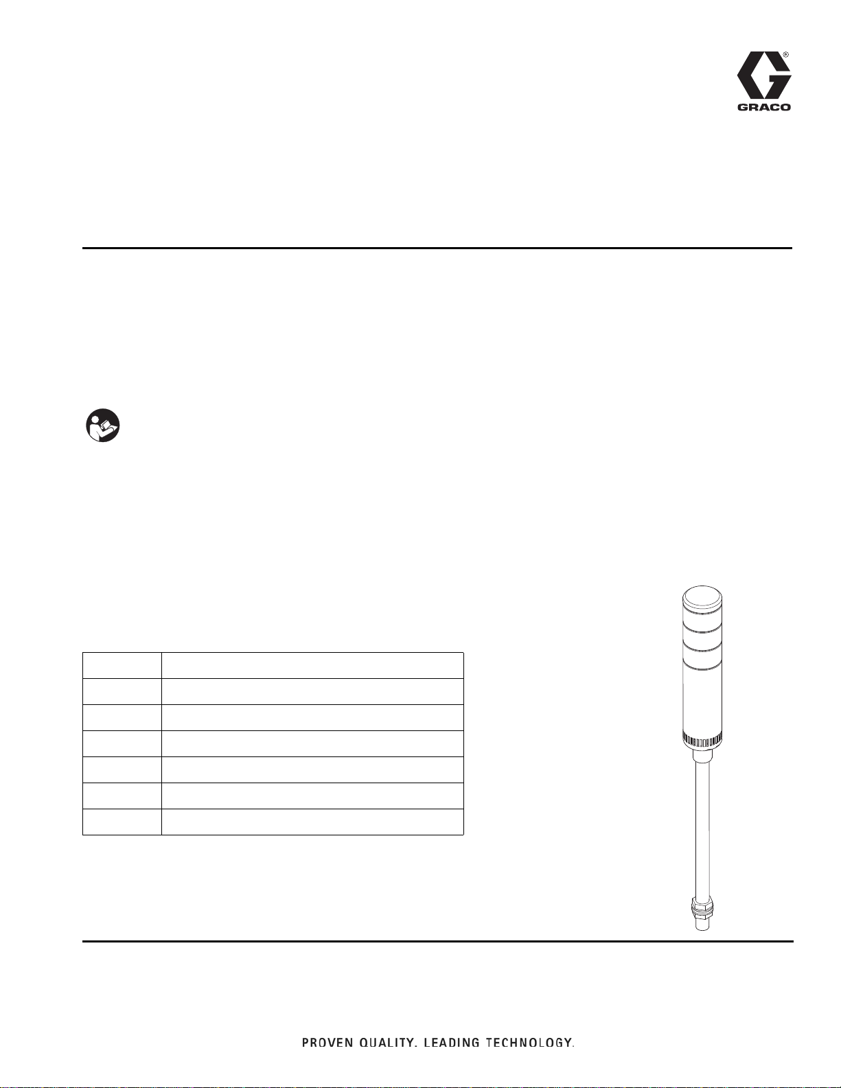
122193 Beacon Tower Installation
313542F 3
122193 Beacon Tower Installation
Install on a ProMix 2KS
NOTE: Beacon Tower 122193 is for ProMix 2KS auto-
matic systems (ADxxxx or RDxxxx), or manual systems
with wire harness 15W023 installed.
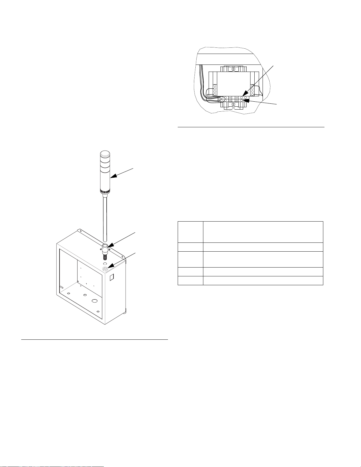
1. Feed wires through the hole in adapter (A) and
secure the adapter to beacon (1) with set screws.
2. Remove the 3/4 in. (19 mm) knockout on top of the
EasyKey. Feed the wires through the hole and
secure the beacon (1) with the jam nut (N) and
washer on the inside of the box. See FIG. 1.
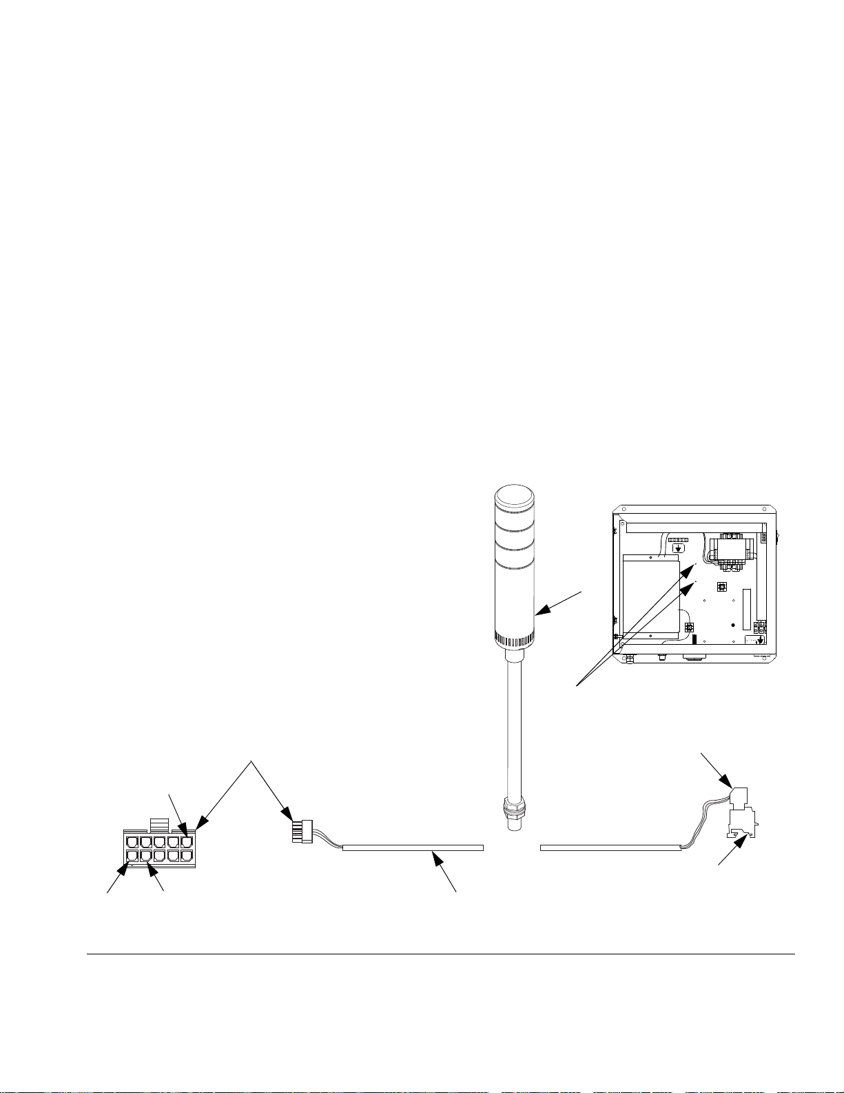
3. Connect yellow and gray wires from beacon to the
power terminal. See FIG. 2.
4. Connect orange, brown, and red wires to header
pins 6, 7, and 8. See FIG. 5 on page 6.
5. To enable the optional audible alarm, connect pur-
ple wire to pin 6 on header. See FIG. 5 on page 6.
When enabled, it will sound for all system alarms.
6. When beacon wiring is completed, insulate the end
of each unused lead wire with insulation tape.
Install on a ProMix 2KE
1. Disconnect the existing alarm from pins 1 and 2 on
the terminal strip. See FIG. 3.
2. Mount the beacon near the control box and secure
with the jam nut (N) and washer. Feed the wires into
the box.
3. Connect the gray wire from the beacon to pin 12 on
the terminal strip.
4. Connect the yellow wire from the beacon to pin 2 on
the terminal strip.
5. Connect either the orange or red wire to pin 1 on the
terminal strip.
6. To enable the optional audible alarm, connect pur-
ple wire to pin 1 on the terminal strip. When
enabled, it will sound for all system alarms.
7. When beacon wiring is completed, insulate the end
of each unused lead wire with insulation tape.
FIG. 3. Beacon Connections in Control Box, ProMix 2KE
ti15730a
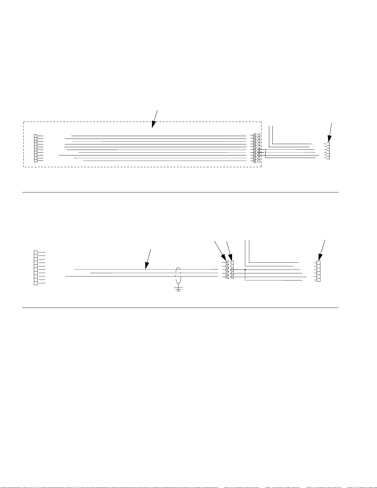
NOTE: Purple wire is for
optional audible alarm.
GRAY
YELLOW
Beacon Wires Schematic
12 12 14
ORANGE OR RED
PURPLE