Graco 24U176 Operation manual

Instructions-Parts
Air Compressor and Dryer
Kit
332733A
EN
Air compressor and air dryer for Reactor® 2 E-30i and E-XP2i integrated plural component proportioning
systems. For professional outdoor use only. Not approved for use in e plosive atmospheres or
hazardous locations.
Important Safety Instructions
Read all warnings and instructions in this manual and in the Reactor®
2 Integrated Elite Systems Manual.
Save these instructions.
24U176
PROVEN QUALITY. LEADING TECHNOLOGY.
All manuals and user guides at all-guides.com

Contents
Warnings ........................................................... 2
Install Air Compressor......................................... 3
Install Air Dryer................................................... 3
Connect Air ines ............................................... 3
Connect Cables.................................................. 4
Electrical Schematics.......................................... 6
Parts.................................................................. 9
Technical Specifications...................................... 17
Graco Standard Warranty.................................... 18
Warnings
The following warnings are for the setup, use, grounding, maintenance, and repair of this equipment. The
exclamation point symbol alerts you to a general warning and the hazard symbols refer to procedure-specific
risks. When these symbols appear in the body of this manual or on warning labels, refer back to these
Warnings. Product-specific hazard symbols and warnings not covered in this section may appear throughout
the body of this manual where applicable.
WARNING
ELECTRIC SHOCK HAZARD
This equipment must be grounded. Improper grounding, setup, or usage of the system can
cause electric shock.
• Turn off and disconnect power at main switch before disconnecting any cables and before
servicing equipment.
• Connect only to grounded power source.
• All electrical wiring must be done by a qualified electrician and comply with all local codes
and regulations.
B RN HAZARD
Equipment surfaces and fluid that is heated can become very hot during operation. To avoid
severe burns:
• Do not touch hot fluid or equipment.
2332733A
All manuals and user guides at all-guides.com

Install Air Compressor
Reference parts illustration, Parts, page 9 .
1. Install air compressor frame (1) and air dryer
frames (2) on pallet with screws (723). eave
nuts and bolts loose.
Note
The fuel tank may need to be removed
to gain access to the frame mounting
screws.
2. Remove two existing nuts (N) from system and
secure frame (2) to system with nuts (N). Torque
to 40 ft-lbs (54 N•m).
Note
Shift or tilt the proportioner forward to
gain alignment.
3. Connect air compressor frame (1) and air dryer
frame (2) with frame (3).
4. Tighten all bolts and nuts.
5. Install end caps (37).
6. Install two motor brackets (29) with screws (31)
on top of frame (1).
Use lifting device to prevent personal injury
when lifting the compressor. Do not overlap
lifting straps over tubing or other fragile
components.
7. ift air compressor on top of brackets (29) and
secure to brackets with screws (30).
8. Install motor starter (10) to bracket (12) with
screws (14) and nuts (15). Attach to air
compressor frame (1) with screws (31).
9. Install switch box enclosure (17) on air control
panel with screws (18).
Install Air Dryer
Reference parts illustration, Parts, page 9 .
1. Connect air dryer outlet fittings and dump valve
(16), (24–268), and (40) and install on dryer as
shown.
2. ift air dryer onto frame (2) and align with fan
facing the engine. Install a nut (5) on the bottom
of each threaded rod to the end of the thread.
Thread rods (9) through nuts in bracket (2) and
secure with nuts pre-installed on rod.
3. Connect clamp bracket (8) to rods (9) with nuts
(5).
4. Connect elbow fitting (32), barbed fitting (33) and
rubber hose (34) to fitting. Secure hose (34) with
clamp (38) and route hose to drain pail.
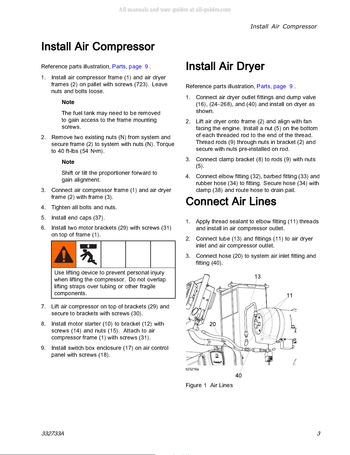
Connect Air Lines
1. Apply thread sealant to elbow fitting (11) threads
and install in air compressor outlet.
2. Connect tube (13) and fittings (11) to air dryer
inlet and air compressor outlet.
3. Connect hose (20) to system air inlet fitting and
fitting (40).
Figure 1 Air ines
332733A 3
All manuals and user guides at all-guides.com

Connect Cables
Connect Cables
1. Turn off the 120/240 VAC alternator circuit
breaker (CB10).
Figure 2
2. Connect motor starter compressor power
cable to air compressor power junction box.
Remove junction box cover from air compressor.
Insertwiresincableendmarked“AIR-CMP
MTR-STR” from starter box (12) through strain
relief and connect with wire nuts (39). See
Electrical Schematics, page 6 . Reassemble
cover.
24U079
WHT
BLK
GRN
GROUND
STUD
BLK 5
BLU 1
RED 8
YEL 4
AC-W1-W5 AC-W4-W8
AC-GND
CORD GRIP
16M826
CABLE 24U079
TO MOTOR STARTER
MOTOR JUNCTION BOX
WIRE NUT
#6
WIRE NUT
#6
ti23262a
Figure 3 Motor Starter Compressor Power
3. Connect motor starter compressor
overtemperature cable to compressor
over-temperature switch in enclosure (31).
WHT
BLK
16X011
AC-OT1
AC-OT2
CORD GRIP
260067
117625
CABLE 16X011
TO MOTOR STARTER
AIR COMPRESSOR OVER TEMPERATURE BOX
OVER
TEMPERATURE
SENSOR
16Y809
127581
ti23259a
Figure 4 Motor Starter Overtemperature Switch
4. Connect motor starter cable to the start/stop
switch enclosure.
WHT
BLK
RED
24U076
SS-1 SS-3
SS-2
SS-4
CORD GRIP
260067
117625
CABLE 24U076
TO MOTOR STARTER AIR COMPRESSOR START STOP BOX
STOP
SWITCH
START
SWITCH
ti23416a
Figure 5 Start/Stop Switch Enclosure
5. Connect motor starter cable to air dryer
connector. See Electrical Schematics, page 6 .
6. Route power cables from motor starter and air
compressor towards the electrical enclosure.
See Cable Routing, page 11.
4332733A
All manuals and user guides at all-guides.com

Connect Cables
7. Use a screw driver to punch out two 3/4 in.
knockouts. Install cord grips (23) at bottom hole
and (43) in upper hole.
ELECTRICAL ENCLOSURE TI23260a
Figure 6
8. oosen the nut on the cord grips (23, 43). Insert
power cable (128) through lower cord grip (23)
and cable (131) through upper cord grip (43).
9. Connect the black and white wire from cable
(128) to CB06 and the green wire to the ground
bus bar GB02 inside the electrical enclosure.
24U078
24U080
WHT
BLK
GRN
WHT
BLK
GRN
PD-GND2
PD-GND2
PD-CB6-2
PD-CB6-4
PD-CB8-4
PD-N
GND2
GROUND BAR
122313
CB05 CB06 CB07 CB08
20A 40A 20A 15A
CORD GRIP
121171
CORD GRIP
16M826
CABLE 24U078
TO MOTOR STARTER
CABLE 24U080
TO MOTOR STARTER
ELECTRICAL
ENCLOSURE
NEUTRAL
ti23263a
Figure 7 Electrical Enclosure
10. Connect cable (131) black wire to CB08 and
white wire to Neutral. Connect the green wire to
the ground bus bar, GB02 inside the electrical
enclosure. See Fig. 7.
11. Tighten nut on the cord grips (23, 43).
12. Route all cables along proper routes. See
Cable Routing, page 11. Use wire ties (42) to
hold against frames.
13. Turn CB06 and CB08 on.
14. Turn on the 120/240 VAC alternator circuit
breaker (CB10).
Figure 8
332733A 5
All manuals and user guides at all-guides.com

Electrical Schematics
Air Compressor Wiring Diagram
AIR COMPRESSOR
AND MOTOR ASSEMBLY
16Y567
MOTOR STARTER BOX
ELECTRICAL ENCLOSURE
START STOP BOX
TI23219a
6332733A
All manuals and user guides at all-guides.com

Electrical Schematics
Air Compressor Junction Boxes
24U078
24U080
WHT
BLK
GRN
WHT
BLK
GRN
WHT
BLK
RED
24U079
WHT
BLK
GRN
24U076
GROUND
STUD
WHT
BLK
16X011
AC-OT1
AC-OT2
BLK 5
BLU 1
RED 8
YEL 4
AC-W1-W5 AC-W4-W8
AC-GND
SS-1 SS-3
SS-2
SS-4
PD-GND2
PD-GND2
PD-CB6-2
PD-CB6-4
PD-CB8-4
PD-N
GND2
GROUND BAR
122313
CB01 CB02 CB03 CB04 CB05 CB06 CB07 CB08
5A 15A 15A 30A 20A 40A 20A 15A
CORD GRIP
121171
CORD GRIP
16M826
CORD GRIP
16M826
CORD GRIP
260067
117625
CORD GRIP
260067
117625
CABLE 24U078
TO MOTOR STARTER
CABLE 24U080
TO MOTOR STARTER
CABLE 24U079
TO MOTOR STARTER
CABLE 16X011
TO MOTOR STARTER
CABLE 24U076
TO MOTOR STARTER
MOTOR JUNCTION BOX
AIR COMPRESSOR OVER TEMPERATURE BOX
AIR COMPRESSOR START STOP BOX
ELECTRICAL
ENCLOSURE
BREAKER DIN RAIL
24T061
WIRE NUT
#6
STOP
SWITCH
START
SWITCH
OVER
TEMPERATURE
SENSOR
16Y809
127581
NEUTRAL
WIRE NUT
#6
ti23220a
8
Strip all wires to 3/4 in. ( x mm). Twist wires
together. Attach wire nuts (40) and wrap wire nut
with electrical tape so that the wire nut will not
come loose.
9
Remove cover from compressor. nsert wires
from starter box through strain relief. Connect as
shown and reassemble cover.
332733A 7
All manuals and user guides at all-guides.com

Electrical Schematics
Motor Starter
L1 L2 L3
T1 T2 T3
95 96 97 98
A1 A2
13
14
23
24
WHT
MS-T3
MS-T1
MS-GND
MS-GND
MS-T2
16X009 BLK
WHT
BLK
GRN
24U080
BLK
GRN
MS-GND
MS-GND
MS-98
MS-98
WHT
BLK
GRN
BLK
WHT
BLK
GRN
WHT
WHT
BLK
RED
WHT
BLK
MS-QD1
MS-QD1
MS-L1
MS-L2
MS-L3
MS-A2
MS-A1
MS-A1
MS-23
MS-13
MS-14
MS-24
MS-96
MS-95
MS-QD2
MS-QD2
GROUND BAR
119257
CORD GRIP
16M826
CORD GRIP
16M826
CORD GRIP
16M826
CORD GRIP
16M826
CABLE 16X011
TO COMPRESSOR OVER TEMP SENSOR
CABLE 24U076
TO COMPRESSOR START STOP BOX
CABLE 16X012
TO AIR DRYER
CABLE 24U079
TO AIR COMPRESSOR
CABLE 24U080
TO ELECTRICAL ENCLOSURE
AIR COMPRESSOR POWER
CABLE 24U078
TO ELECTRICAL ENCLOSURE
AIR DRYER POWER
CABLE 16X010
TO AIR EXHAUST VALVE
Motor STARTER
WITH BOX
24U081
16X010
24U078
AUXILIARY
CONTACTOR
24U082
24U079
16X012
24U076
16X011
ti23221a
8332733A
All manuals and user guides at all-guides.com

Parts
Parts
24U176, Complete Air Compressor it
1
Apply anaerobic sealant to all non-swivel pipe
threads.
2
Torque to 40 ft-lbs (54 N•m).
332733A 9
All manuals and user guides at all-guides.com

Parts
1
Apply anaerobic sealant to all non-swivel pipe
threads.
4
Use from safety label (135) left inside starter box
(10).
10 332733A
All manuals and user guides at all-guides.com

Parts
Cable Routing
2
Do not allow cables from starter box to touch
engine. Secure all cables with cable ties (42) to
frame approximately where shown every 6–12
in. as needed.
3
Secure with cable ties (42) to pallet tie downs
where shown.
332733A 11
All manuals and user guides at all-guides.com

Parts
4
Parts included with compressor (6b)
5
Coupler supplied with compressor (6b) needs to
be pressed on to motor (6a) as shown in detail
view.
6
Torque to 20 ft.-lbs (27 N•m).
8
Torque to 34 ft.-lbs (46 N•m).
9
Torque to 36 ft.-lbs (43 N•m).
10
Discard key supplied with motor and replace with
key (6j).
11
Discard plug supplied on compressor and install
thermal switch (6h).
12
Discard lift ring to install flange.
13
Discard steel washer on (6g) before assembly.
14
Use only Hydrovane Fluid Force Red 2000
compressor oil. Fill to top of fill plug opening.
One gallon container, Part No. 17A101, is
available as an accessory.
12 332733A
All manuals and user guides at all-guides.com

Parts
Ref Part Description Qty.
1 16W780 FRAME, air compressor 1
2 16W685 FRAME, air dryer 1
3 16W713 STRAP, frame connector 1
4 121488 SCREW, hex hd, flanged;
2.75 in. (70 mm), 3/8–16 10
5112958 NUT, hex, flanged; 3/8–16 12
6 16Y567 COMPRESSOR, 5 hp 1
6a 127364 MOTOR, 5 hp 1
6b --- COMPRESSOR, tankless 1
6c 107530 SCREW, cap, sch, hex 2
6d 16X024 COVER overload switch 1
6e 260067 FITTING, strain relief, 1/2 npt 1
6f 117625 NUT, locking 1
6g 16M826 CORD, grip, 3/4 in. 1
56h 16Y809 SWITCH, thermal overload 1
6j 16C282 KEY, square, 1/4 1
6k 127581 WASHER, bonded seal 1
7127298 DRYER, air 1
8 16W689 BRACKET, clamp 1
9 16W843 ROD, threaded, 3/8-16 4
10 24U083 STARTER, motor,
reactor, integrated; see
Motor Starter, page 15
1
11 C20679 FITTING, elbow 2
12 16W565 BRACKET, electrical box 1
13 16X402 TUBE, compressor - air dryer 1
14 101577 SCREW, cap, hex hd 3
15 113505 NUT, keps, hex hd 3
16 125644 FITTING, branch tee, 1/2 npt 1
17 24T849 ENC OSURE, switch box;
see Switch Box Enclosure,
page 14
1
Ref Part Description Qty.
18 119865 SCREW, mach, hex serrated 2
20 218093 HOSE, coupled 1
21 16W577 ENC OSURE, rear 1
22 125856 SCREW, 8-32, serrated
flange 3
23 16M826 CORD, grip, 3/4 in. 1
24 15E511 FITTING, union, swivel 1/2 x
1/4 1
25 156971 FITTING, nipple, short 1
26 16X520 VA VE, air, 3-way, din 1
27 C19264 P UG, pipe plug 1/4 in. 1
28 512910 MUFF ER, polyethylene 1/4
in. npt 1
29 16X808 BRACKET, motor mount 2
30 112395 SCREW, cap, flng hd 4
31 111194 SCREW,capflanghd 6
32 112538 FITTING, elbow, street, 90
deg 1
33 127108 FITTING, barbed, 5/16 id x
1/8 npt 1
34 17A346 HOSE,rubber,5/16in.;6ft
(1.8 m) 1
35 125871 TIE, cable, 7.50 in. 3
37 111218 CAP, tube, square 2
38 125163 C AMP, hose, 7/32 in. - 5/8
in. 1
39 16Y488 NUT, wire, #14-#6 awg 2
40 190451 UNION, adapter 1
41 106569 TAPE, electrical 1
42 261105 TIE, cable, 14 in. 10
43 121171 FITTING, cable strain relief 1
332733A 13
All manuals and user guides at all-guides.com

Parts
Switch Box Enclosure
24T849
1
Assemble switch blocks as shown.
Ref Part Description Qty
101 16W575 ENC OSURE, front 1
102 121618 SWITCH, start, push
button, green 1
103 121619 SWITCH, stop, push
button, red 1
104 120493 ATCH, mounting 2
105 120494 B OCK, switch, N.O. 1
Ref Part Description Qty
106 120495 B OCK, switch, N.C. 1
107 260067 FITTING, strain relief, 1/2
npt 1
108 117625 NUT, locking 1
109 16W614 ABE 1
14 332733A
All manuals and user guides at all-guides.com

Parts
Motor Starter
24U083
1
Attach ground connector bar aligned vertically to
electrical box with screw and washer.
2
Labels from sheet (735).
332733A 15
All manuals and user guides at all-guides.com

Parts
24U083
3
Torque to 38–42 in.-lbs (4.3–4.7 N•m).
4
Torque to 18–22 in.-lbs (2–2.5 N•m).
5
Torque to 28–32 in.-lbs (3.1–3.6 N•m).
Ref Part Description Qty
121 24U081 STARTER, int. reactor,
3phase 1
122 24U082 CONTACT, aux, two no
switches 1
123 119257 CONNECTOR, bar,
ground 1
124 555582 SCREW, soc hd cap, #10 1
125 555629 WASHER, #10, external
tooth lock 1
126 16M826 CORD, grip, 3/4 in. 4
127 16X009 CAB E, shunt 1
Ref Part Description Qty
128 24U080 CAB E, air compressor
breaker 1
129 24U079 CAB E, air compressor 1
130 16X011 CAB E, over
temperature, compressor 1
131 24U078 CAB E, dryer, breaker 1
132 16X012 CAB E, power, dryer 1
133 24U076 CAB E, start-stop 1
134 16X010 CAB E, pressure vent 1
135
▲
16X422 ABE 1
▲
Replacement Warning labels, signs, tags, and
cards are available at no cost
16 332733A
All manuals and user guides at all-guides.com

Technical Specifications
Air Compressor and Dryer Kit
.S. Metric
Total System oad (Watts) See Reactor 2 Elite Integrated system manual.
Available Auxiliary Current See Reactor 2 Elite Integrated system manual.
Rotary Vane Air Compressor
Hydrovane Model V04 (P RS type), continuous run
Part No. 025CK10
Pressure 140 psi 0.9 MPa, 9.6 bar)
Specifications 16 cfm
Thermal overload switchRequired Features
Safety Relief Valve
Motor: Baldor
Part No. E 1410–CUS
Specifications 5 HP, 1735 RPM, 240 V, 1 Phase, OPSB
Required Features C face, lift rings,
Refrigerated Air Dryer
Hankison Model H1T20
Specifications 115VAC, 1 Phase, 60 Hz, 22 scfm at 150 psi (1 MPa, 10.3 bar)
Required Features Pilot valve unloader
332733A 17
All manuals and user guides at all-guides.com

Graco Standard Warranty
Graco warrants all equipment referenced in this document which is manufactured by Graco and bearing its
name to be free from defects in material and workmanship on the date of sale to the original purchaser for use.
With the exception of any special, extended, or limited warranty published by Graco, Graco will, for a period of
twelve months from the date of sale, repair or replace any part of the equipment determined by Graco to be
defective. This warranty applies only when the equipment is installed, operated and maintained in accordance
with Graco’s written recommendations.
This warranty does not cover, and Graco shall not be liable for general wear and tear, or any malfunction,
damage or wear caused by faulty installation, misapplication, abrasion, corrosion, inadequate or improper
maintenance, negligence, accident, tampering, or substitution of non-Graco component parts. or shall Graco
be liable for malfunction, damage or wear caused by the incompatibility of Graco equipment with structures,
accessories, equipment or materials not supplied by Graco, or the improper design, manufacture, installation,
operation or maintenance of structures, accessories, equipment or materials not supplied by Graco.
This warranty is conditioned upon the prepaid return of the equipment claimed to be defective to an authorized
Graco distributor for verification of the claimed defect. If the claimed defect is verified, Graco will repair or replace
free of charge any defective parts. The equipment will be returned to the original purchaser transportation
prepaid. If inspection of the equipment does not disclose any defect in material or workmanship, repairs will be
made at a reasonable charge, which charges may include the costs of parts, labor, and transportation.
THIS WARRANTY IS EXCLUSIVE, AND IS IN LIEU OF ANY OTHER WARRANTIES, EXPRESS OR IMPLIED,
INCLUDING BUT NOT LIMITED TO WARRANTY OF MERCHANTABILITY OR WARRANTY OF FITNESS
FOR A PARTICULAR PURPOSE.
Graco’s sole obligation and buyer’s sole remedy for any breach of warranty shall be as set forth above. The
buyer agrees that no other remedy (including, but not limited to, incidental or consequential damages for lost
profits, lost sales, injury to person or property, or any other incidental or consequential loss) shall be available.
Any action for breach of warranty must be brought within two (2) years of the date of sale.
GRACO MAKES NO WARRANTY, AND DISCLAIMS ALL IMPLIED WARRANTIES OF MERCHANTABILITY
AND FITNESS FOR A PARTICULAR PURPOSE, IN CONNECTION WITH ACCESSORIES, EQUIPMENT,
MATERIALS OR COMPONENTS SOLD BUT NOT MANUFACTURED BY GRACO.
These items sold, but not
manufactured by Graco (such as electric motors, switches, hose, etc.), are subject to the warranty, if any, of
their manufacturer. Graco will provide purchaser with reasonable assistance in making any claim for breach of
these warranties.
In no event will Graco be liable for indirect, incidental, special or consequential damages resulting from Graco
supplying equipment hereunder, or the furnishing, performance, or use of any products or other goods sold
hereto, whether due to a breach of contract, breach of warranty, the negligence of Graco, or otherwise.
FOR GRACO CA ADA CUSTOMERS
The Parties acknowledge that they have required that the present document, as well as all documents, notices
and legal proceedings entered into, given or instituted pursuant hereto or relating directly or indirectly hereto, be
drawn up in English. Les parties reconnaissent avoir convenu que la rédaction du présente document sera en
Anglais, ainsi que tous documents, avis et procédures judiciaires exécutés, donnés ou intentés, à la suite de ou
en rapport, directement ou indirectement, avec les procédures concernées.
Graco Information
For the latest information about Graco products, visit www.graco.com.
To plac an ord r,
contact your Graco Distributor or call to identify the nearest distributor.
Phon :
612-623-6921
or Toll Fr :
1-800-328-0211
Fax:
612-378-3505
All written and visual data contained in this document reflects the latest product information available at the time of publication.
Graco reserves the right to make changes at any time without notice.
For patent information, see www.graco.com/patents.
Original Instructions. his manual contains English. MM 332733
Graco Headquarters:
Minneapolis
International Offices:
Belgium, China, Japan, Korea
GRACO INC. AND SUBSIDIARIES • .O. BOX 1441 • MINNEA OLIS MN 55440-1441 • USA
Copyright 2014, Graco Inc. All Graco manufacturing locations are registered to ISO 9001.
www.graco.com
All manuals and user guides at all-guides.com
Other manuals for 24U176
1
Other Graco Dryer manuals
Popular Dryer manuals by other brands

Bosch
Bosch WTG86401TC Installation and operating instructions

RevAir
RevAir B07F6WPRHD operating manual

Whirlpool
Whirlpool WED9150 Use and care guide

Tricity Bendix
Tricity Bendix TM 310 W Operating & installation instructions

Kenmore
Kenmore 2696478100 Features list

Bosch
Bosch WTA74201SG Installation and operating instructions