Graco PR70 Series Parts list manual

3A6225A
EN
Instructions - Parts
PR70™to PR70f™
Conversion Kit
For adding flow control features to a PR70 for accurate metering, mixing, and dispensing
of two-component material with the capability to dispense beads.
For professional use only.
Not approved for use in explosive atmospheres or hazardous locations.
See page 3 for model information
Important Safety Instructions
Read all warnings and instructions in this
manual and in all related manuals before
using the equipment. Save all instruc-
tions.

23A6225A
Contents
Related Manuals . . . . . . . . . . . . . . . . . . . . . . . . . . . 3
Models . . . . . . . . . . . . . . . . . . . . . . . . . . . . . . . . . . . 3
Overview . . . . . . . . . . . . . . . . . . . . . . . . . . . . . . . . . . 4
Component Identification . . . . . . . . . . . . . . . . . . . . 5
Installation . . . . . . . . . . . . . . . . . . . . . . . . . . . . . . . . 6
Install the Conversion Kit . . . . . . . . . . . . . . . . . . 6
Startup . . . . . . . . . . . . . . . . . . . . . . . . . . . . . . . . . . . 9
Using the Advanced Display Module . . . . . . . . . 9
Parts . . . . . . . . . . . . . . . . . . . . . . . . . . . . . . . . . . . . 10
Fixed Ratio Kits . . . . . . . . . . . . . . . . . . . . . . . . . 10
Variable Ratio Kits . . . . . . . . . . . . . . . . . . . . . . 12
Electrical Schematics . . . . . . . . . . . . . . . . . . . . . . 14

Related Manuals
3A6225A 3
Related Manuals
Models
NOTE: All models contain software upgrade token U82161.
PR70 Operation and Parts Manuals
Part Description
312759 PR70™and PR70v™with Advanced Display Module
Operation - Maintenance Manual
312760 PR70 and PR70v Repair and Parts Manual
334984 PR70f™with Flow Control Operation - Maintenance
Manual
3A1244 GCA Module Programming
Part No. Description For Existing PR70 Configuration
Fixed Ratio
25E179 PR70 Fixed Ratio Flow Control Conversion Kit With Hydracheck and pressure transducers
25E180 PR70 Fixed Ratio Flow Control Conversion Kit
with Hydracheck Conversion Kit (24W336) With pressure transducers only
25E181 PR70 Fixed Ratio Flow Control Conversion Kit
with Pressure Transducer Conversion Kit (257433) With Hydracheck only
25E182
PR70 Fixed Ratio Flow Control Conversion Kit
with Hydracheck (24W336) and Pressure Transducer
Conversion Kits (257433)
Base machine only
Variable Ratio
25E183 PR70 Variable Ratio Flow Control Conversion Kit With Hydracheck and pressure transducers
25E184 PR70 Variable Ratio Flow Control Conversion Kit
with Hydracheck Conversion Kit (25E187) With pressure transducers only
25E185 PR70 Variable Ratio Flow Control Conversion Kit
with Pressure Transducer Conversion Kit (257433) With Hydracheck only
25E186
PR70 Variable Ratio Flow Control Conversion Kit
with Hydracheck (25E187) and Pressure Transducer
Conversion Kits (257433)
Base machine only

Overview
43A6225A
Overview
These instructions describe how to convert a fixed ratio
or variable ratio PR70 to a PR70f with flow control. Hav-
ing the flow control feature on a PR70 provides the
capability to dispense beads of material. Flow control
can only be used on PR70 configurations that include
the Advanced Display Module (ADM).
For general information about PR70 configurations, refer
to the Product Configurator section in manuals 312759
and 312760, or contact Graco Ohio Customer Service at
1-800-746-1334.
NOTE: The parts that differentiate the PR70f from a
standard PR70 are shown in Parts starting on page 10.
Hydracheck Option
The Hydracheck option is required when using the flow
control function. Hydracheck regulates the speed or
feed rate of the pump. Flow control performs best if the
majority of the pump restriction is external to the mate-
rial flow or is from a restriction in the material path prior
to the mixing point. See Figure 1 on page 5for the loca-
tion of the Hydracheck on a PR70 with flow control.
Pressure Transducers Option
The pressure transducers option is required when using
the flow control function. Pressure transducers produce
a reading that works in conjunction with the software.
The reading is integral for the stall out pressure at the
end of the dispense (no “snake head”) and the minimum
and maximum dispense pressure fault. See Figure 1 on
page 5for the location of the pressure transducers on a
PR70 with flow control.

Component Identification
3A6225A 5
Component Identification
PR70f
NOTE: Figure 1 shows the flow control conversion kit installed. The ADM, shield, tank, dispense valve, and fluid con-
trol module (FCM) connections have been removed to allow clear identification of key components.
Key:
A Voltage to Pressure Regulator
B Fluid Control Module (FCM)
C FCM Mounting Board Assembly
D Terminal Strip
E Air Fittings
F Hydracheck (Required for flow control feature)
G Shield Locking Screw
H DC Power Supply
J Power Switch
K Air Inlet
L Air Pressure Relief Switch
M Pressure Transducers (Required for flow control feature)
FIG. 1: PR70f with Flow Control Installed
F
C
B
D
E
A
H
G
K
J
L
M

Installation
63A6225A
Installation
Install the Conversion Kit
1. Follow the Pressure Relief and Shutdown Proce-
dure in the PR70 and PR70v Operation - Mainte-
nance manual. See Related Manuals on page 3.
2. Turn off the PR70 at the power switch (J) and
unplug the power cord.
3. Disconnect the air hose from the air inlet (K)
4. Use a 6 mm Allen wrench to turn the shield locking
screws (G) clockwise on both sides of the PR70 to
release the PR70 protective shield. See Figure 2.
5. Remove the protective shield as shown in Figure 2
to access the Fluid Control Module (FCM) mounting
board.
6. Remove all of the connections from the FCM includ-
ing the low level sensor cables from ports 3 and 4 if
applicable. See Figure 3.
NOTE: It is recommended that you mark or label the
cables to correctly identify them for reconnection.
7. Remove the air lines from the regulator assembly air
fittings.
8. Refer to Figure 4. Remove the FCM assembly from
the mounting plate.
9. Remove the FCM base and regulator assembly
from the mounting board.
10. Remove the cable splitter from the FCM mounting
board.
WARNING
PRESSURIZED FLUID HAZARD
The equipment in this system stays pressurized until
pressure is manually relieved. To help prevent serious
injury from pressurized fluid, such as skin injection,
splashing fluid and moving parts, follow the Pressure
Relief Procedure described in your PR70 system
manual when you stop pumping and before cleaning,
checking or servicing the equipment.
PERSONAL PROTECTIVE EQUIPMENT
Wear appropriate protective equipment when in the
work area to help prevent serious injury, including eye
injury, hearing loss, inhalation of toxic fumes, and
burns.
FIG. 2
G
Shield
FCM Mounting
Board
FIG. 3
FIG. 4
Regulator Assembly
FCM Assembly
FCM Base
Cable Splitter

Installation
3A6225A 7
11. Remove the mounting board from the PR70 frame
as shown in Figure 5.
12. Attach the new FCM mounting board assembly (C)
to the PR70 frame using the fasteners that were
removed in step 10. See Figure 6 below.
13. Reattach the FCM base and assembly (B) and the
cable splitter to the new mounting board (C) using
the existing screws that were removed in steps
8-10.
14. Reattach the air lines to the air fittings (E) on the
new voltage to pressure regulator as shown in Fig-
ure 8.
NOTE: If the current air lines are worn or damaged,
replacement air lines are included in this kit. You can cut
them to fit your needs.
15. If you are using low level sensors, attach the two
cables with the M8 male ends from the terminal strip
(D) on the new assembly to ports 3 and 4 on the
fluid control module. See Figure 7 above and Fig-
ure 3 on page 6.
16. Attach the two cables with the M8 female ends from
the terminal strip on the new assembly to the exist-
ing low level sensor cables.
FIG. 5
FIG. 6
C
FIG. 7
FIG. 8
DCable Splitter
B
E

Installation
83A6225A
17. Pressure transducers (M) are required to work with
the voltage to pressure regulator. See Parts starting
on page 10. If the current PR70 configuration does
not have pressure transducers, refer to the PR70
and PR70v Repair-Parts manual for installation.
See Related Manuals on page 3.
18. A Hydracheck (F) is required to work with the volt-
age to pressure regulator option. See Parts starting
on page 10. If your current PR70 configuration does
not have a Hydracheck, refer to the PR70 and
PR70v Repair-Parts manual for installation. See
Related Manuals on page 3.
19. Connect the power cord and turn on power to the
PR70 at the power switch (J).
20. Load the software from the new programming token.
See the CGA Module Programming manual for
information on loading the new software. See
Related Manuals on page 3.
21. Connect the air line to the air inlet (K).
22. Reattach the shield, and secure it with the shield
locking screws (G).
23. Refer to Startup on page 9for next steps.

Startup
3A6225A 9
Startup
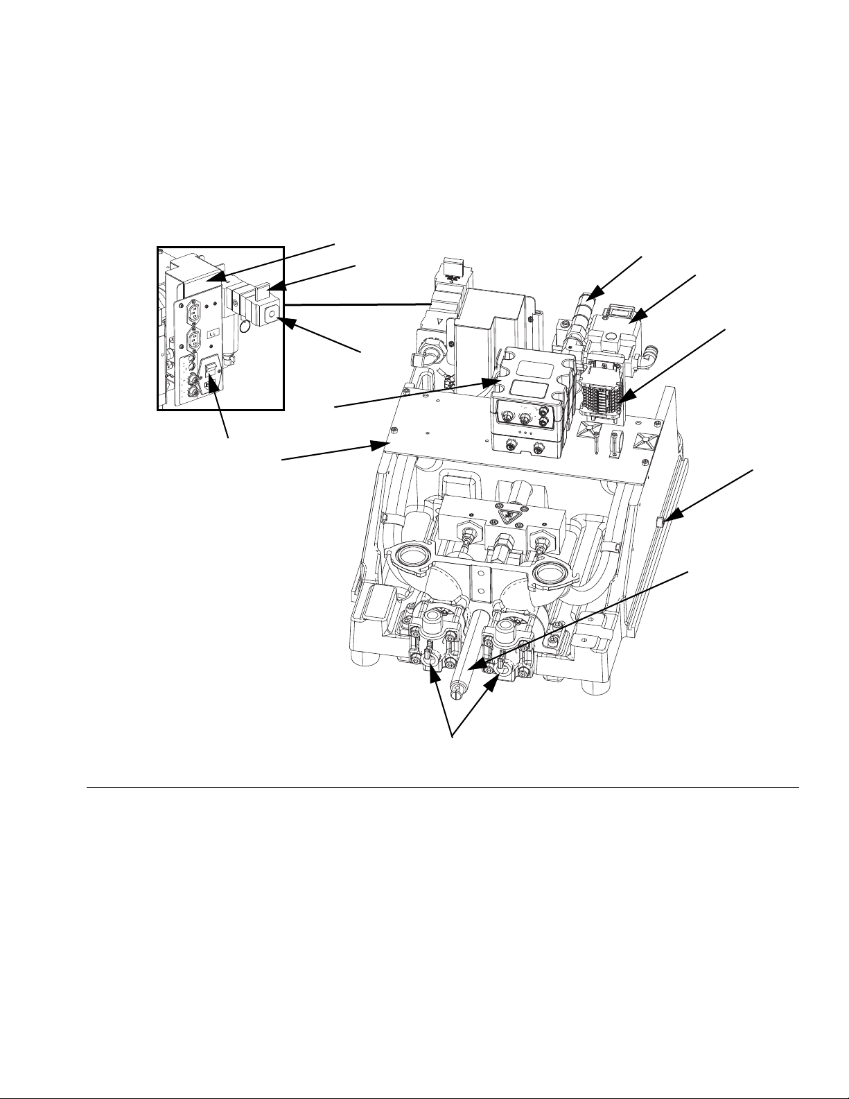
If the newly converted PR70f is not turned on, locate the
power switch (J) at the rear of the machine and turn the
power on. The Advanced Display Module (ADM) will
automatically turn on and begin to load.
With the air line connected to the machine at the air inlet
(K), slide up the system air pressure relief switch (L). It
is the yellow tab on the air inlet at the rear of the
machine. The hole in the tab should not be showing.
Using the Advanced Display
Module
When the main electrical power is turned on, the Graco
splash screen will be displayed on the ADM until com-
munication and initialization is complete.
The ADM will operate in any mode other than Disabled
(shown below). Press the Mode Select soft key to
change to another operating mode. Once you have
selected the desired mode, press the ADM’s Enter key
to accept it.
There are two types of screens on the ADM: Run and
Setup screens. The ADM starts in the Run screens. To
access the Setup screens, press . If the password
feature is enabled, you need to enter the password
when prompted to access the Setup screens. Use the
numeric keypad to enter the password, then press
.
Refer to the PR70f with Flow Control Operation - Main-
tenance manual for information about the available
screens. See Related Manuals on page 3.
WARNING
PERSONAL PROTECTIVE EQUIPMENT
Wear appropriate protective equipment when in the
work area to help prevent serious injury, including eye
injury, hearing loss, inhalation of toxic fumes, and
burns.
NOTICE
To prevent damage to soft keys buttons, do not press
the buttons with sharp objects such as pens, plastic
cards, or fingernails.

Parts
10 3A6225A
Parts
Fixed Ratio Kits
FIG. 9: Kits 25E179 - 25E182 Parts
14
3
2
Quantity
Ref Part Description 25E179 25E180 25E181 25E182
1 U82159 BRACKET, control, sub-assy, pr70, fc 1 1 1 1
2 257433 CABLE, transducer, pres, pr70, 2 pum 11
3 24W336 KIT, hydracheck 1 1
4 U82161 SOFTWARE, assy with token, pr70f, co 1 1 1 1

Parts
3A6225A 11
U82159 FCM Mounting Board Assembly
* Not shown.
: U82159
FIG. 10: U82159 Parts
105
109
102 101
103
104x2
106 108x4 107
115
116
117
120
119 119
119
Ref Part Description Qty
101 127396 REGULATOR, electro/pneumatic, 3/8 in. npt 1
102 121019 FITTING, elbow, male, swivel, 3/8 in. npt 1
103 120954 MANIFOLD, inlet, banjo 1
104 551903 SCREW, cap, sch, 1/4 x 1/2 2
105 U60656 BRACKET, controls, pr70, fc, fixted 1
106 U60657 BLOCK, regulator mount 1
107 25E444 STRIP, terminal, pr70fc 1
108 117126 SCREW, shcs m5 x 16 4
109 100518 SCREW, mach, pnhd 2
110 U70851* CABLE, m12 x bare leads, .5 mtr 1
111 U70850* CABLE, m8 x bare leads, .5 mtr 2
112 U70849* CABLE, m8 90 x bare leads, .5 mtr 2
115 125030 STRAP, wire, 1 in. 1
116 61/2906-BK/11 HOSE, .245 id x .375 od, pu, 95 dur 4 ft
117 61/2904-BK/11 HOSE, .160 id x .250 od, pu, 95 dur 4 ft
119 84/0805/89 CABLE, tie mount, 1 x 1 sq w/ adhesive 3
120 94/0533/96 FITTING, elbw, street, 3/8 npt, 90 deg, 1
122 81/0721/11* FERRULE, red, (1,00/8 mm^2), 18 awg 5
123 81/0725/11* FERRULE, lt blue, 24 awg 8

Parts
12 3A6225A
Variable Ratio Kits
FIG. 11: Kits 25E183 - 25E186 Parts
201 204
203
202
Quantity
Ref Part Description 25E183 25E184 25E185 25E186
201 U82421 BRACKET, control, sub-assembly, pr70 1 1 1 1
202 257433 CABLE, transducer, pres, pr70, 2 pum 11
203 25E187 KIT, hydracheck, pr70vr 1 1
204 U82161 SOFTWARE, assy with token, pr70f, co 1 1 1 1

Parts
3A6225A 13
U82421 FCM Mounting Board Assembly
* Not shown.
FIG. 12: U82421 Parts
301
304x2
317
303
302
305
314
306
307
306
308x4
309
327
316
315
Ref Part Description Qty
301 127396 REGULATOR, electro/pneumatic, 3/8 in. npt 1
302 121019 FITTING, elbow, male, swivel, 3/8 in. npt 1
303 120954 MANIFOLD, inlet, banjo 1
304 96/0162/98 SCREW, shc, 1/4-20 x 0.50, ss 2
305 U60809 BRACKET, control mounting, pr70v, fc 1
306 U60657 BLOCK, regulator mount 1
307 25E444 STRIP, terminal, pr70fc 1
308 121194 SCREW 4
309 100518 SCREW, mach, pnhd 2
310 U70851* CABLE, m12 x bare leads, .5 mtr 1
311 U70850* CABLE, m8 x bare leads, .5 mtr 2
312 U70849* CABLE, m8 90 x bare leads, .5 mtr 2
314 U60810 SPACER, regulator mount, pr70v, fc 1
315 125030 STRAP, wire, 1 in. 1
316 61/2906-BK/11 HOSE, .245 id x .375 od, pu, 95 dur 2
317 61/2904-BK/11 HOSE, .160 id x .250 od, pu, 95 dur 4
319 84/0805/89* CABLE, tie mount, 1 x 1 sq w/ adhesive 3
324 81/0721/11* FERRULE, red, (1,00/8 mm^2), 18 awg 5
325 81/0725/11* FERRULE, lt blue, 24 awg 8
327 94/0533/96 FITTING, elbw, street, 3/8 npt, 90 deg, 1

Electrical Schematics
14 3A6225A
Electrical Schematics
FIG. 13: Electric Schematic - Page 1
NOTE: Fluid Control Module
#2 applies only to models with
optional features included.
See Figure 16.
See Figure 16.
See Figure 16.

Electrical Schematics
3A6225A 15
FIG. 14: Electric Schematic - Page 2

Electrical Schematics
16 3A6225A
FIG. 15: Electric Schematic - Page 3
Fig. 16
Fig. 16
Fig. 16
Fig. 16

Electrical Schematics
3A6225A 17
NOTE: See the PR70 and PR70V Operation - Maintenance manual 312759 for Optional External Control Interface
instructions.
FIG. 16: Electric Schematic - Page 4
2
1
4
5
1
3
2
4
5
1
3
2
Customer Supplied
Dry Contact/Relay
Customer Supplied
Dry Contact/Relay
SHOT SEL - BIT 0
SHOT SEL - BIT 3
Not Used
COMMON
SHOT SEL - BIT 1
SHOT REQUEST - INPUT
FAULT OUTPUT
INTERRUPT - CAN - REQ - INPUT
COMMON
READY - OUTPUT
Brown
Gray
Black
Blue
White
Brown
+24 VDC
+24 VDC
Gray
Black
Blue
White
NOTE: Connector #1 is for use
with all systems.
NOTE: View shown is looking at
pins on end of cable.
NOTE: Connector #2 is for use
with systems with an Advanced
Display Module only.
NOTE: View shown is looking at
pins on end of cable.

All written and visual data contained in this document reflects the latest product information available at the time of publication.
Graco reserves the right to make changes at any time without notice.
Original instructions. This manual contains English. MM 3A6225
Graco Headquarters: Minneapolis
International Offices: Belgium, China, Japan, Korea
GRACO INC. AND SUBSIDIARIES • P.O. BOX 1441 • MINNEAPOLIS MN 55440-1441 • USA
Copyright 2016, Graco Inc. All Graco manufacturing locations are registered to ISO 9001.
www.graco.com
Revision A, March 2019
Graco Information
Sealant and Adhesive Dispensing Equipment
For the latest information about Graco products, visit www.graco.com.
For patent information, see www.graco.com/patents.
TO PLACE AN ORDER, contact your Graco distributor, go to www.graco.com, or call to identify the nearest
distributor.
If calling from the USA: 1-800-746-1334
If calling from outside the USA: 0-1-330-966-3000
Other manuals for PR70 Series
10
This manual suits for next models
1
Table of contents
Other Graco Media Converter manuals
Popular Media Converter manuals by other brands

Net Media
Net Media NM-UTPSET Specifications

superbrightleds
superbrightleds DMX3-3CH-8A user manual

Vivo Link
Vivo Link VL120015 user manual

Black Box
Black Box PCA45A Specifications

Tripp Lite
Tripp Lite Console Converter For SUN B011-000 user manual

Blackmagicdesign
Blackmagicdesign ATEM Camera Converter Installation and operation manual