manuals.online logo
Brands
  1. Home
  2. •
  3. Brands
  4. •
  5. Graco
  6. •
  7. Water Pump
  8. •
  9. Graco Ratio President Hydra-Spray B 222-293 Operation manual

Graco Ratio President Hydra-Spray B 222-293 Operation manual

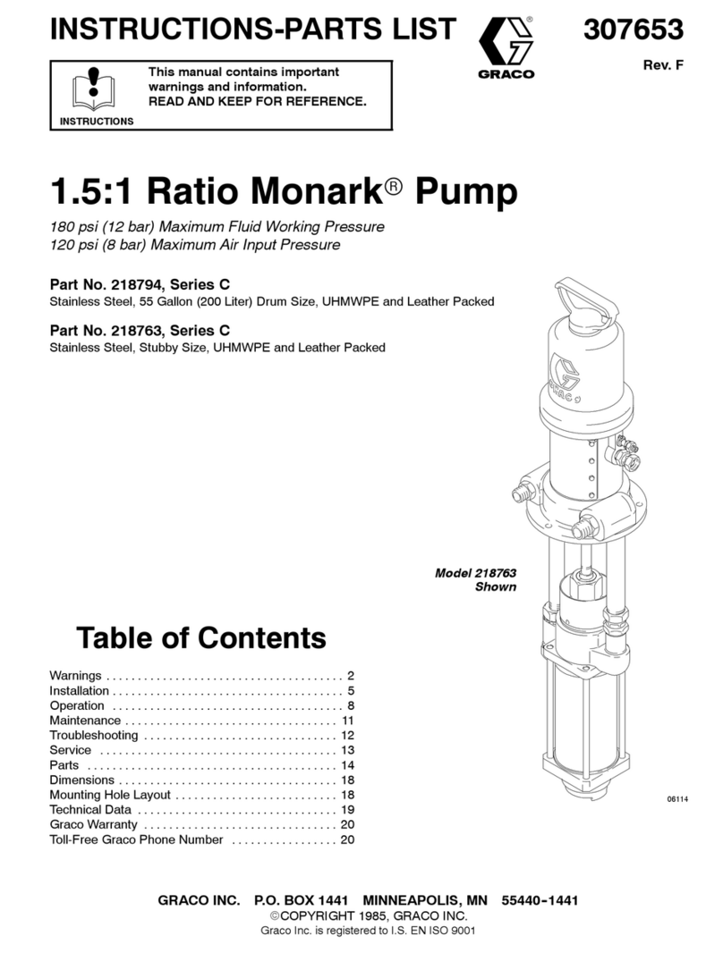
307–934
Rev. H
Supersedes D
and PCN E
Model
222–293
Shown

INSTRUCTIONS-PARTS
LIST
INSTRUCTIONS
This
manual contains important
warnings and information.
READ AND KEEP FOR REFERENCE.
WALL MOUNT, AIR–ASSISTED AIRLESS
15:1
Ratio President

Hydra–Spray
Pump
WALL MOUNT SYSTEMS
1800 psi (12 MPa, 124 bar) MAXIMUM WORKING PRESSURE
∗ Model 222–293, Series B
For cold spray systems
Includes pump and wall bracket
Model 231–075
For cold spray systems
Includes pump 222–293, fluid regulation kit 222–564,
hose, gun and tip
∗ Model 222–294
For heated spray systems
Includes pump 222–293, V
iscon
Heater
,
heater mounting kit 222–269, and circulating kit
222–436

Specify desired voltage of heater
(see page 25 for available models).
Refer to page 2 for T
able of Contents.
∗
GRACO INC. P.O. BOX 1441
MINNEAPOLIS, MN
55440–1441
COPYRIGHT
1988, GRACO INC.
Graco
Inc. is registered to I.S. EN ISO 9001
2
307–934
Table
of Contents
Warnings 2.
. . . . . . . . . . . . . . . . . . . . . . . . . . . . . . . . . . . . .
Setup 5
. . . . . . . . . . . . . . . . . . . . . . . . . . . . . . . . . . . . . . . . .
Operation
16.
. . . . . . . . . . . . . . . . . . . . . . . . . . . . . . . . . . .
Parts
NO
TAG18.
. . . . . . . . . . . . . . . . . . . . . . . . . . . . . . . .
Accessories 25
. . . . . . . . . . . . . . . . . . . . . . . . . . . . . . . . . .
Mounting
Dimensions
25.
. . . . . . . . . . . . . . . . . . . . . . . . .
Technical
Data
27.
. . . . . . . . . . . . . . . . . . . . . . . . . . . . . . .
Warranty 28
. . . . . . . . . . . . . . . . . . . . . . . . . . . . . . . . . . . . .
Graco T
oll-Free Phone Number
28.
. . . . . . . . . . . . . . . .
Symbols
Warning Symbol
WARNING
This
symbol alerts you to the possibility of serious
injury or death if you do not follow the instructions.
Caution Symbol
CAUTION
This
symbol alerts you to the possibility of damage to
or destruction of equipment if you do not follow the
instructions.
WARNING
INSTRUCTIONS
Equipment misuse can cause the equipment to rupture or malfunction and result in serious injury
.

This equipment is for professional use only
.

Read all instruction manuals, tags, and labels before operating the equipment.

Use the equipment only for its intended purpose. If you are not sure, call your Graco distributor
.

Do not alter or modify this equipment.

Check equipment daily
. Repair or replace worn or damaged parts immediately
.

Do not exceed the maximum working pressure of the lowest rated system component. Refer to the
T
echnical Data
on page 27 for the maximum working pressure of this equipment.

Use fluids and solvents which are compatible with the equipment wetted parts. Refer to the
Tech-
nical Data
section of all equipment manuals. Read the fluid and solvent manufacturer
’
s warnings.

Route hoses away from traffic areas, sharp edges, moving parts, and hot surfaces. Do not expose
Graco hoses to temperatures above 180
F (82
C) or below –40
F (–40C).
W
ear hearing protection when operating this equipment.

Do not lift pressurized equipment.

Comply with all applicable local, state, and national fire, electrical, and safety regulations.
3
307–934
WARNING
INJECTION HAZARD
Spray
from the gun, leaks or ruptured components can inject fluid into your body and cause extremely
serious injury, including the need for amputation. Fluid splashed in the eyes or on the skin can also
cause serious injury
.

Fluid injected into the skin might look like just a cut, but it is a serious injury
.
Get immediate medi
-
cal attention.

Do not point the gun at anyone or at any part of the body
.

Do not put your hand or fingers over the spray tip.

Do not stop or deflect leaks with your hand, body
, glove or rag.

Do not “blow back” fluid; this is not an air spray system.

Always have the tip guard and the trigger guard on the gun when spraying.

Check the gun dif
fuser operation weekly
. Refer to the gun manual.

Be sure the gun trigger safety operates before spraying.

Lock the gun trigger safety when you stop spraying.

Follow the
Pressure Relief Procedure
on page 16 if the spray tip clogs and before cleaning,
checking or servicing the equipment.
T
ighten all fluid connections before operating the equipment.

Check the hoses, tubes, and couplings daily
. Replace worn or damaged parts immediately.
Do not repair high pressure couplings; you must replace the entire hose.

Use only Graco approved hoses. Do not remove the spring guard that is used to help protect the
hose from rupture caused by kinks or bends near the couplings.
MOVING
P
ARTS HAZARD
Moving
parts can pinch or amputate your fingers.

Keep clear of all moving parts when starting or operating the pump.

Before servicing the equipment, follow the
Pressure Relief Procedure
on page 16 to prevent the
equipment from starting unexpectedly
.
4
307–934
WARNING
FIRE AND EXPLOSION HAZARD
Improper
grounding, poor ventilation, open flames or sparks can cause a hazardous condition and
result in a fire or explosion and serious injury
.

Ground the equipment and the object being sprayed. Refer to
Grounding
on page 5.

If there is any static sparking or you feel an electric shock while using this equipment,
stop spray-
ing immediately
.
Do not use the equipment until you identify and correct the problem.

Provide fresh air ventilation to avoid the buildup of flammable fumes from solvents or the fluid
being sprayed.

Keep the spray area free of debris, including solvent, rags, and gasoline.

Electrically disconnect all equipment in the spray area.

Extinguish all open flames or pilot lights in the spray area.

Do not smoke in the spray area.

Do not turn on or of
f any light switch in the spray area while operating or if fumes are present.

Do not operate a gasoline engine in the spray area.
TOXIC FLUID HAZARD
Hazardous
fluid or toxic fumes can cause serious injury or death if splashed in the eyes or on the skin,
inhaled, or swallowed.

Know the specific hazards of the fluid you are using.

Store hazardous fluid in an approved container
. Dispose of hazardous fluid according to all local,
state and national guidelines.

Always wear protective eyewear
, gloves, clothing and respirator as recommended by the fluid and
solvent manufacturer
.
5
307–934
Setup
General Information
NOTE:
Reference numbers and letters in parentheses
in the text refer to the callouts in the figures and the
parts drawing.
NOTE:
Always use Genuine Graco Parts and Acces
-
sories, available from your Graco distributor
. If you
supply your own accessories, be sure they are ade
-
quately sized and pressure rated for your system.
Figure 2 is only an example for selecting and installing
system components and accessories. Contact your
Graco distributor for assistance in designing a system
to suit your particular needs.
Prepare the Operator
All
persons who operate the equipment must be
trained in the safe, ef
ficient operation of all system
components as well as the proper handling of all fluids.
All operators must thoroughly read all instruction
manuals, tags, and labels before operating the equip
-
ment.
Prepare the Site
The
pump requires 12 scfm (0.34 m

/min) of com
-
pressed air while operating at 400 kPa (4 bar
, 60 psi)
air pressure and a flow rate of 3.8 liters/min (1.0 gpm).
Ensure that you have an adequate compressed air
supply.
Refer to Figure 2. Bring a compressed air supply line
(B) from the air compressor to the pump location. Be
sure all air hoses are properly sized and pressure-
rated for your system. Use only electrically conductive
hoses.
Install a bleed-type shutof
f valve (G) in the air line to
isolate the air line components for servicing. Install an
air line moisture trap and drain valve (A) to help re
-
move moisture from the compressed air supply
.
Keep the site clear of any obstacles or debris that
could interfere with the operator
’
s movement.
Have a grounded, metal pail available for use when
flushing the system or draining the fluid filter
.
Grounding
WARNING
FIRE AND EXPLOSION HAZARD
Before operating the pump, ground the
system as explained below
. Also read
the section
FIRE OR EXPLOSION
HAZARD
on page 4.
1.
Pump (for pumps without pre–installed ground
wire):
use the ground wire and clamp (supplied).
See Fig. 1. Loosen the grounding lug locknut (W)
and washer (X). Insert one end of the ground wire
(Y) into the slot in lug (Z) and tighten the locknut
securely
. Connect the other end of the wire to a
true earth ground.
Fig. 1
Z
X
W
Y

2.
Air and fluid hoses:
use only electrically conductive
hoses.
3.
Heater
, if used:
refer to heater manual 307–805.
4.
Air compressor:
follow manufacturer
’
s recommen
-
dations.
5.
Spray gun:
ground through connection to a prop
-
erly grounded fluid hose and pump.
6.
Fluid supply container:
follow your local code.
7.
Object being sprayed:
follow your local code.
8.
Solvent pails used when flushing:
follow your local
code. Use only metal pails, which are conductive,
placed on a grounded surface. Do not place the
pail on a nonconductive surface, such as paper or
cardboard, which interrupts the grounding continu
-
ity.
9.
T
o maintain grounding continuity when flushing or
relieving pressure
, hold a metal part of the spray
gun firmly to the side of a grounded
metal
pail,
then trigger the gun.
6
307–934
Setup
Supplied Components and Accessories
Refer
to Figure 2.
WARNING
A bleed-type master air valve (27) and a fluid drain
valve (13) are required, to help reduce the risk of
serious injury
, including fluid injection and splashing
of fluid in the eyes or on the skin, and injury from
moving parts if you are adjusting or repairing the
pump.
The bleed-type master air valve relieves air trapped
between this valve and the pump after the air is
shut of
f. T
rapped air can cause the pump to cycle
unexpectedly
. Locate the valve close to the pump.
The fluid drain valve assists in relieving fluid pres
-
sure in the displacement pump, hose, and gun.
T
riggering the gun to relieve pressure may not be
sufficient.

The main air line filter (A)
removes harmful dirt
and moisture from compressed air supply
.

A second bleed–type air valve (G)
isolates the air
line accessories for servicing. Locate upstream
from all other air line accessories.

The air line lubricator (C)
provides automatic
lubrication of air motor
.
The fluid drain valve (13)
assists in relieving fluid
pressure in displacement pump, hose, and gun.
T
riggering gun only
, may not be suf
ficient to relieve
pressure.

The air relief valve (15)
opens automatically to
relieve air pressure to pump if pressure exceeds a
preset level. This valve prevents overpressurization
of spray gun

The air regulators (18)
control pump speed and
outlet pressure by adjusting air pressure to pump.
The right air regulator controls air pressure to
pump. The left air regulator controls air pressure to
gun.

The bleed–type master air valve (27)
relieves air
trapped between this valve and pump. See the
WARNING
at left. T
rapped air can cause pump to
cycle unexpectedly
.
T
o bleed air from pump, right
air regulator (18) must be open when master air
valve is closed.
06776A
KEY
AAir
Line Filter
B
Main Air Line
C
Air Line Lubricator
D
Fluid Hose
E
Spray Gun
F
Gun Air Supply Hose
GBleed–T
ype Air V
alve
Y
Ground Wire
1Pump
8
Fluid Filter
13
Drain V
alve (Required)
15
Air Relief V
alve
18
Air Regulators
23
Suction Kit
27 Bleed–T
ype Master Air
V
alve (Required)
B
C
D
E
F
Y
1
8
13
15
18
18
23
27
G
Fig.
2
A
7
307–934
Setup
System Setup
Refer
to paragraphs on this page to setup pump
Models 222–293 and 231–075, for use in cold spray
systems.
Refer to page 9 to setup pump Model 222–294, for
use in heated spray systems, or to convert pump
Model 222–293 to a heated system.
T
o convert pump Model 222–293 to a heated unit,
order the following:
Viscon
Fluid Heater (choose one of three
models)
– Model 220–522 (120 V
, single–phase, 16.7
Amp)
– Model 220–523 (240 V
, single–phase, 9.6
Amp)
– Model 220–524 (480 V
, single–phase, 4.8
Amp)

Heater Mounting Kit 222–269

Circulating Kit 222–436
Pump Setup
(Models 222–293 and 231–075)
Refer
to Figure 3.
NOTE:
Apply pipe sealant (3) to all male threads,
except at swiveling connections.
1.
Mount the pump wall bracket (7) 5 ft (1.5 m) above
the floor
. Be sure the wall is strong enough to
support the weight of the pump and accessories,
fluid, hoses, and stress caused during pump
operation. Refer to “Mounting Dimensions” on
page 25 and Mounting Bracket manual 306–783.
2.
The air regulators (18), manifold (28), bleed valve
(27) and connecting parts are preassembled. The
left
air regulator controls air pressure to the gun,
and the
right
regulator controls pressure to the
pump. The flow arrows on both regulators
must
point away from the manifold (28).
3.
If you are installing a heated system,
skip step 4
and proceed to “Heated System Setup” on
page 9.
4.
Connect the air and fluid hoses and gun as ex
-
plained below
.
Hose and Gun Setup
Connect
one end of the fluid hose (D) to the filter (8)
outlet nipple and the other to the fluid inlet of the gun
(E). DO NOT install the spray tip in the gun yet. To use
a second gun with the sprayer
, refer to page 12.
Close the bleed–type master air valve (27) and both
the air regulators (18). Connect the main air line (B) to
the bleed valve (27). Connect an air supply hose (F) to
the outlet nipple of the gun (left) air regulator
. Connect
the other end of the hose to the gun’
s air inlet.
Fluid Regulation Kit 222–564 Setup
(Pump Model 231–075)
WARNING
Before
installing the fluid regulation kit, follow the
Pressure
Relief Procedure
on page 16. Discon
-
nect
all hoses from the pump.
Assemble the fluid regulation kit (51) as shown in
Detail A of Fig. 3. (Refer also to the parts list on page
20.) Install the mounting bracket (51k) on the regulator
(51f) using the two screws (51p) and lockwashers
(51q). Connect the fluid regulator and bracket to the
side of the wall bracket (7) using the screw (51l),
lockwasher (51m) and nut (51n). Connect the 22” (560
mm) hose (51h) to the outlet nipple of the fluid filter
(8).
Connect the gun air supply hose (F) between the air
inlet of the gun (E) and the outlet nipple of the gun
(left) air regulator.
Connect the fluid hose (D) between the gun fluid inlet
and the outlet nipple (51b) of the fluid regulation kit.
8
307–934
Setup
APPLY
PIPE
SEALANT (3)
51b
51d
51a
7
51b
51c
51e
51f
51h 51j
51k
51l 51m
51n
51p
51q
B
Fig.
3
APPLY
PIPE
SEALANT (3)
7
1
2
15
9
18
28
18
27
22
5
16
16
14
17
9
8
H
A
A
23
DET
AIL A (MODEL 231–075)
Fluid Regulation Kit 222–564
includes items 51a–51q.
51h
(REF)
(SEE
DET
AIL A)
B
13
12
10
10
06777A
9
307–934
Setup
Heated System Setup
(Models 222–294 and 222–293 conversion)
Refer
to Figure 4.
Use the following procedures to setup Model 222–294
Heated System, or to convert an existing Model
222–293 to a heated system. The V
iscon
Heater is
available in three voltages (see page 25). Specify
which voltage you desire.
T
o setup the pump, first follow steps 1–3 under “Pump
Setup” on page 7.
WARNING
The Viscon Heater must be installed by a qualified
electrician in compliance with all state and local
codes and regulations, to reduce the risk of electric
shock
or other
serious bodily injury during installation
or
operation.
The power supply must match the heater ’s require-
ments (see “Accessories” on page 25). Refer to the
Viscon Heater Manual, 307–805, for further in-
formation.
WARNING
Heat
causes fluid to expand, If fluid in the heated
por
-
tion of your system is trapped with nowhere to ex-
pand, it can cause a system rupture. A system rup-
ture can result in serious bodily injury and property
damage.
Be sure your system has an adequate
way
to
handle heat expansion.

Use flexible hoses between the heater and gun.

OR, install a properly sized accumulator down
-
stream from the heater
.

OR, install a pressure relief valve, (Graco P/N
237–061) to relieve pressure when it exceeds
the system’
s maximum working pressure.

And, never install any shutof
f device between
the heater and g;un. If you are using a fluid
regulator before the gun, never use it as a
shutof
f device.
Installing Heater Mounting Kit 222–269
WARNING
Before installing the heater, heater mounting kit
and
circulating
kit, follow the
Pressure Relief
Procedure
on
page 16. Disconnect all hoses from the pump.
NOTE:
Reference numbers marked with an asterisk
(for example, 29*) are included in kit 222–269.
Apply pipe sealant (3*) to all male threads, except at
swiveling connections.
1.
Be sure the wall is strong enough to support the
weight of the heater
, hoses, fluid, and stress
caused during operation. Locate the heater wall
bracket (29*) holes 9.25” (235 mm) to the left of
the pump bracket holes, and at the same height.
Use the heater wall bracket as a template to mark
the wall. See “Mounting Dimensions” on page 25.
2.
Attach the heater wall bracket to the heater mount
-
ing posts with the M8 x 1.25 screws and lockwash
-
ers supplied with the heater (53).
3.
Use M8 or 5/16” bolts of the appropriate length
and lockwashers (not supplied) to fasten the
heater bracket to the wall.
4. If you are converting an existing pump,
remove
the fluid filter (8) and long 3/8 npt nipple (9) from
the pump fluid outlet. Discard the long nipple (9).
See Fig. 3.
5.
Install the 3/8 npt nipple (35*) in the heater outlet.
Screw the fluid filter (8) inlet onto this nipple.
Unscrew the 1/4 npt nipple (1
1) from the filter
outlet. Screw the elbow (47*) into the filter outlet,
and screw the 1/4 npt nipple (1
1) into the elbow
.
6.
Screw the elbow (30*) into the heater
’
s inlet.
Attach the heater hose (31*) to the elbow
. Attach
the rigid end of the union (32*) to the other end of
the hose (31*).
7.
Screw the bushing (46*) into the pump outlet, then
screw the elbow (34*) into the bushing. Screw the
check valve (33*) into the elbow
. Be sure the arrow
on the check valve points down. T
o complete the
heater connection to the pump, screw the swivel
end of the union (32*) onto the check valve (33*).
10
307–934
Setup
Installing Circulating Kit 222–436
Refer
to Figure 4.
WARNING
Before installing the heater, heater mounting kit and
circulating
kit, follow the
Pressure Relief
Procedure
on
page 16. Disconnect all hoses from the pump.
NOTE:
Reference numbers marked with a symbol (for
example, 36

) are included in kit 222–436. Some kit
parts are not used on this pump.
Apply pipe sealant (3

) to all male threads, except at
swiveling connections.
1. If you are converting an existing pump, remove
the suction kit (23) from the pump’
s fluid intake.
See Fig. 3.
2.
Unscrew the swivel elbow (H) from the end of the
suction kit (23) and discard the elbow
. See Fig. 2.
Screw the rigid end of the manifold (36

) onto the
pump intake, and attach its swivel end to the
suction kit (23).
3.
Screw the mounting stud (41

) into the outlet in
the base of the back pressure regulator (40
).
Install the fluid pressure gauge (45

) in the inlet of
the back pressure regulator
. Remove the plugs
from the optional inlet and outlet of the back pres
-
sure regulator
. Install one 1/4 npt nipple (1
1) in
the regulator
’
s optional outlet (K), and the other
1/4 npt nipple (1
1
) in the optional inlet (J).
4.
Place a lockwasher (42

) and washer (43

) on the
mounting stud, and insert the stud through the
mounting hole in the right side of the pump wall
bracket (7). Secure the regulator with a lockwasher
(42
) and nut (44

) on the inside of the pump wall
bracket.
5.
Install the CIRC end of the three–way ball valve
(37
) in the open port of the pump fluid intake
manifold (36

). Screw the elbow (47

) onto the IN
branch of the three–way valve. Connect one end
of the hose (39

) to this elbow
, and the other end
to the nipple (1
1
) at the back pressure regulator
’s
optional outlet (K).
6.
Connect the drain hose (38

) to the DRAIN end of
the three–way valve (37
).
7.
Connect the fluid return line to the nipple (1
1) at
the back pressure regulator
’
s optional inlet (J).
8.
Connect the air and fluid hoses and gun as ex
-
plained on page 7.
11
307–934
Setup
06778A
SPECIFY
DESIRED
HEA
TER VOL
TAGE
Fig.
4
PART
OF
HEA
TER (53)
29*
11
8
35*
47*
30*
31*
A
A
31*
32*
23
33*
34*
46*
36
38
3747
23
39
11
(J)
11
(K)
40
45
41
42
44
43
1
B
B
C
C
ARROW ON BODY
MUST POINT DOWN
12
13
53
7
9
15
14
16
22
18
12
307–934
Setup
Converting to a Two–Gun System
To
convert your sprayer to a two–gun system, order
parts listed, and perform assembly procedures. Refer
to this page for model 222–293. For models 231–075
and 222–294, see page 15).
Model 222–293 Two–Gun Conversion
(Refer
to Figs 5 and
6, and the Parts Drawing on
page 18)
WARNING
Before performing this procedure, follow the Pres-
sure Relief Procedure on page 16. Disconnect all
hoses
from the pump.
For Model 222–293, order the following parts:
Part No. Description Qty
156–877
NIPPLE; 1/2 npt; 2.5” long
2
158–683 ELBOW
, 90

; 1/2 npt (m x f)
2
103–475
TEE; 1/2 npt(f) run;
1/2 npt(f) branch
1
104–267 AIR REGULATOR 1
101–180 GAUGE, pressure, air 1
100–509
PLUG, pipe; 1/4 npt
1
166–999 ELBOW
, street, reducing;
1/2 npt(m) x 1/4 npt(f)
1
162–453
NIPPLE; 1/4 npt x 1/4 npsm
2
238–402 SPRAY GUN, AA plus air–assisted
airless 2
205–406
HOSE, air; nylon; 1/4” ID;
cpld 1/4 npsm (fbe) swivel;
25 ft (7.6 m) long
2
214–698
HOSE, fluid; nylon; 3/16” ID;
cpld 1/4 npsm(f) swivel x
1/4 npt(m); 25 ft (7.6 m) long
2
1. Remove
the gun air regulator (18) from the nipple
(24) coming of
f the air manifold (28). Do not re
-
move any parts from the regulator
. Save the
regulator for use in step 4. See figure 5.
2.
Install a 101–180 Gauge (P) and 100–509 Plug
(Q) on a 104–267 Air Regulator (R). Screw a
166–999 Elbow (S) into the outlet port of this air
regulator
, and screw a 162–453 Nipple (T) into the
elbow.
3.
Screw the branch of the 103–475 T
ee (L) onto the
nipple (24) at the air manifold (28). Install a
156–877 Nipple (M) in each open port of the tee.
Screw a 158–683 Elbow (N) onto each nipple.
4.
Install the air regulator removed in step 1 onto one
of the elbows (N). This is the air control for the first
gun. Install the air regulator assembled in step 2
onto the other elbow (N), so both regulators are
facing the same way
. This is the air control for the
second gun.
5.
Remove the plug (10) from the optional outlet port
of the fluid filter (8). Install a 162–453 Nipple (T) in
its place. See Detail A of Fig 6. This is the fluid
connection for the second gun.
6.
Connect the fluid and air hoses to the guns as
explained on page 7 (see Detail E of Fig 6).
13
307–934
Setup
06779
Fig. 5
28
24
N
Q
TSR
P
M
L
M
N
18
CONNECT
AIR
HOSE
FOR FIRST
GUN HERE
CONNECT
AIR HOSE
FOR SECOND
GUN HERE
Air Regulator Connections for a T
wo–Gun System (All models)
P
14
307–934
Setup
(FROM
SECOND
GUN)
03260
T
(TO
SECOND
GUN)
T
(TO
SECOND
GUN)
Fig.
6
DETAIL
C:
HOSE CONNECTIONS A
T FLUID
REGULAT
OR (MODEL 231–075)
51f
51a
51b
(TO
FIRST
GUN)
51b
(FROM
FLUID
FILTER)
51j
51e
51c
51d
U
DET
AIL D:
FLUID RETURN CONNECTIONS A
T
BACK PRESSURE REGULA
TOR
(MODEL 222–294)
U
T
11
11
39
40
T
O 3–W
A
Y
VAL
VE (37)
(FROM
FIRST
GUN)
11
(T
O FIRST
GUN)
8
DET
AIL B:
HOSE
CONNECTIONS A
T FLUID
FIL
TER (MODEL 222–294)
47
DET
AIL F:
ASSEMBL
Y OF HOSE KIT AND GUN
(MODEL 222–294)
V
E
AIR LINE
FLUID LINE
FLUID LINE
AIR LINE
FLUID
RETURN
LINE
DET
AIL E:
ASSEMBL
Y OF HOSES AND GUN
(MODELS 222–293 AND 231–075)
E
F
D
DET
AIL A:
HOSE
CONNECTIONS A
T FLUID
FIL
TER (MODEL 222–293)
T
(TO
SECOND
GUN)
11
(TO
FIRST
GUN)
8
03257 03258
03259
15
307–934
Setup
Model 231–075 Two–Gun Conversion
(Refer
to Figs 5 and
6, and the Parts Drawing on
page 20)
WARNING
Before performing this procedure, follow the Pres-
sure Relief Procedure on page 16. Disconnect all
hoses
from the pump.
NOTE:
Model 231–075 includes a hose and gun set,
so you should order only one 238–402 Gun, 205–406
Air Hose, and 214–698 Fluid Hose.
Part No. Description Qty
156–877
NIPPLE; 1/2 npt; 2.5” long
2
158–683 ELBOW
, 90

; 1/2 npt (m x f)
2
103–475
TEE; 1/2 npt(f) run;
1/2 npt(f) branch
1
104–267 AIR REGULATOR 1
101–180 GAUGE, pressure, air 1
100–509
PLUG, pipe; 1/4 npt
1
166–999 ELBOW
, street, reducing;
1/2 npt(m) x 1/4 npt(f)
1
103–048
TEE, street; 1/4 npt(f) branch;
1/4 npt(f) x 1/4 npt(m) run
1
162–453
NIPPLE; 1/4 npt x 1/4 npsm
2
238–402 SPRAY GUN, AA plus air–assisted
airless 2
205–406
HOSE, air; nylon; 1/4” ID;
cpld 1/4 npsm (fbe) swivel;
25 ft (7.6 m) long
1
214–698
HOSE, fluid; nylon; 3/16” ID;
cpld 1/4 npsm(f) swivel x
1/4 npt(m); 25 ft (7.6 m) long
1
1. Perform
steps 1–4 of the procedure for Model
222–293 (see page 10).
2.
Unscrew the gauge (51d) from the cross (51c) of
the fluid regulation kit. Install the 103–048 T
ee (U)
in the cross (see Detail C of Fig 5). Screw a
162–453 Nipple (T) in the branch of the tee (U).
Screw the gauge (51d) in the open port of the tee.
This is the fluid connection for the second gun.
3.
Connect the fluid and air hoses to the guns as
explained on page 6 (see Detail E of Fig 5).
Model 222–294 Two–Gun Conversion
(Refer
to Figs 5 and
6, and the Parts Drawing on
page 22)
WARNING
Before performing this procedure, follow the Pres-
sure Relief Procedure on page 16. Disconnect all
hoses
from the pump.
For Model 222–294, order the following parts:
Part No. Description Qty
238–402 SPRAY GUN, AA plus air–assisted
airless 2
222–264 HOSE KIT
, insulated; nylon;
two fluid lines, one air line;
1/4” ID; cpld 1/4 npsm (fbe)
swivel; 25 ft (7.6 m) long
2
156–877
NIPPLE; 1/2 npt; 2.5” long
2
158–683 ELBOW
, 90

; 1/2 npt (m x f)
2
103–475
TEE; 1/2 npt(f) run;
1/2 npt(f) branch
1
104–267 AIR REGULATOR 1
101–180 GAUGE, pressure, air 1
100–509
PLUG, pipe; 1/4 npt
1
166–999 ELBOW
, street, reducing;
1/2 npt(m) x 1/4 npt(f)
1
162–453
NIPPLE; 1/4 npt x 1/4 npsm
3
103–048
TEE, street;1/4 npt(f) branch;
1/4 npt(f) x 1/4 npt(m) run
1
1. Perform
steps 1–4 of the procedure for Model
222–293 (see page 12).
2.
Remove the plug (10) from the top outlet port of
the fluid filter (8). Install a 162–453 Nipple (T) in its
place. See Detail B of Fig 6.
3.
See Fig 3. Remove the nipple (1
1) from the option
-
al inlet (J) of the back pressure regulator (40).
Save the nipple for later use.
4.
Screw a 103–048 T
ee (U) into the optional inlet of
the back pressure regulator (40), as shown in
Detail D of Fig 6. Install the nipple (1
1) removed in
step 3 in one of the open ports of the tee. Install a
162–453 Nipple (T) in the other open port.
5.
Connect the fluid and air lines of one of the insu
-
lated hose kits (V) to the fluid and air inlets of one
of the guns (E). Repeat for the other hose kit and
gun. See Detail F of Fig 6.
6.
Connect the air line of one of the hose kits (see
Detail F of Fig. 6) to the outlet nipple of one of the
air regulators (see Fig 5). Connect the air line of
the second hose kit to the outlet nipple of the other
air regulator.
7.
Connect the fluid supply line of the first hose kit (V)
to the outlet nipple (1
1) of the fluid filter (8). Con
-
nect the fluid supply line of the second hose kit to
the other outlet nipple (T). See Detail B of Fig 6.
Similarly
, connect the fluid return lines of the two
hose kits (V) to the inlet nipples (1
1 and T) of the
back pressure regulator (40). See Detail D of
Fig 6.
16
307–934
Operation
Pressure Relief Procedure
WARNING
INJECTION
HAZARD
The system pressure must be manually
relieved to prevent the system from
starting or spraying accidentally
. Fluid
under high pressure can be injected through the
skin and cause serious injury
. T
o reduce the risk of
an injury from injection, splashing fluid, or moving
parts, follow the
Pressure Relief Procedure
whenever you:

are instructed to relieve the pressure,

stop spraying,

check or service any of the system equipment,

or install or clean the spray tips.
1.
Lock the gun trigger safety
.
2.
Shut of
f the main power to the heater
, if used.
Circulate the fluid for at least 10 minutes to allow it
and the heater to cool.
3.
Close the red-handled bleed-type master air valve
(G, supplied in your system).
4.
Shut of
f the air regulators.
5.
Unlock the gun trigger safety
.
6.
Hold a metal part of the gun firmly to the side of a
grounded metal pail, and trigger the gun to relieve
pressure.
7.
Lock the gun trigger safety
.
8.
Open the drain valve (13, required in your system),
having a container ready to catch the drainage.
9.
Leave the drain valve open until you are ready to
spray again.
10.
If you suspect that the spray tip or hose is com
-
pletely clogged, or that pressure has not been fully
relieved after following the steps above,
very
slowly
loosen the tip guard retaining nut or hose
end coupling and relieve pressure gradually
, then
loosen completely
. Now clear the tip or hose.
Flushing
WARNING
FIRE AND EXPLOSION HAZARD
Before flushing, read the section
FIRE
OR EXPLOSION HAZARD
on page 4.
Be sure the entire system and flushing
pails are properly grounded. Refer to
Grounding
on page 5.
Flush the pump:

Before the first use

When changing colors or fluids

Before fluid can dry or settle out in a dormant pump
(check the pot life of catalyzed fluids)

Before storing the pump.
CAUTION
Never leave water or water-base fluid in the pump
overnight. If you are pumping water-base fluid, flush
with water first, then with a rust inhibitor such as
mineral spirits. Relieve the pressure, but leave the
rust inhibitor in the pump to protect the parts from
corrosion.
WARNING
T
o reduce the risk of serious injury whenever you
are instructed to relieve pressure, always follow the
Pressure Relief Procedure
on page this page.
1.
Relieve the pressure.
2.
Remove the tip guard and spray tip from the gun.
See the gun instruction manual.
3.
Fill the pail with solvent or place the suction tube in
a container of solvent.
4.
Hold a metal part of the gun firmly to the side of a
grounded
metal
pail.
5.
Start the pump. Always use the lowest possible
fluid pressure when flushing.
6. T
rigger the gun.
7.
Flush the system until clear solvent flows from the
gun.
8.
Relieve the pressure.
17
307–934
Operation
9.
Clean the tip guard and spray tip separately
, then
reinstall them.
10.
Clean the inside and outside of the pail or suction
tube.
Flush with a fluid that is compatible with the fluid you
are pumping and with the wetted parts in your system.
Check with your fluid manufacturer or supplier for
recommended flushing fluids and flushing frequency
.
Starting and Adjusting the Pump
Refer
to figures 3 and 4.
Be sure the air regulators and bleed–type master air
valve are closed.
DO NOT INST
ALL THE SPRA
Y TIP
YET!
Place the suction tube (23) in the fluid pail. Open the
bleed–type master air valve and the gun air regulator
.
Hold a metal part of the spray gun firmly to the side of
a grounded metal pail and trigger the gun. Slowly open
the pump air regulator until the pump starts. Allow the
pump to cycle slowly until all the air is pushed out of
the fluid lines. Release the gun trigger and engage the
safety latch; the pump will stall against the pressure.
With the pump and lines primed, and with adequate air
pressure and volume supplied, the pump will start and
stop as the spray gun is triggered and released.
WARNING
T
o reduce the risk of serious injury whenever you
are instructed to relieve pressure, always follow the
Pressure Relief Procedure
on page 16.
Relieve the pressure,
then install the spray tip in gun.
Use the pump air regulator to control the pump speed
and fluid pressure. Always use the lowest pressure
necessary to achieve the desired results. Higher
pressures waste fluid and cause premature wear of the
pump packings and spray tip.
The fluid regulator (51f) used on pump model 231–075
is a fluid pressure type. It allows you to run the pump
at an “ef
ficient” air pressure (above 210 kPa [2.1 bar
,
30 psi] ) while adjusting fluid pressure with the regula
-
tor
. The back pressure regulator (40, see figure 4)
used on model 222–294 does the same by requiring a
minimum flow rate and also setting the minimum
circulating rate needed to prevent fluid from settling.
Keep the wet–cup filled with Graco Throat Seal Liquid
(TSL) to help prolong the packing life. Check the
tightness of the packing nut weekly
. The packing nut
should be tight enough to prevent leakage – no tighter
.
Always follow the
Pressure Relief Procedure W
arn-
ing
on page 16 before adjusting the packing nut.
Never allow the pump to run dry of the fluid being
pumped. A dry pump will quickly accelerate to a high
speed, possibly damaging itself. If your pump acceler
-
ates quickly
, or is running too fast, stop it immediately
and check the fluid supply
. If the supply container is
empty and air has been pumped into the lines, refill the
supply container and prime the pump and lines with
fluid, being sure to eliminate all air from the fluid sys
-
tem, or flush the pump as described in “Shutdown and
Care”, on this page.
Heated Systems
Operating
instructions for a heated circulating system
are provided in the V
iscon
Heater manual, 307–805.
Read and understand all warnings and instructions in
the heater manual before operating a heated system.
The three–way ball valve (37) can be set for either fluid
circulation or draining. T
o circulate fluid back to the
pump, turn the handle toward the CIRC end of the
valve. T
o drain fluid, turn the handle toward the DRAIN
end.
Shutdown and Care of the Pump
WARNING
To
reduce the risk of serious injury whenever you
are instructed to relieve pressure, always follow the
Pressure Relief Procedure
on page 16.
For overnight shutdown, stop the pump at the bottom
of its stroke to prevent fluid from drying on the ex
-
posed displacement rod and damaging the throat
packings.
Relieve the pressure.
Always flush the pump before the fluid dries on the
displacement rod. See
Flushing
on page16.
18
307–934
Parts
06773A
Model 222–293
,
Series B
Includes items 1–54
1
2
7
8
9
9
10
10
11
11
12
13
14
15
16
17
18
18
19
21
22
23
24
25
26
27
28
16
REF
A
A
54
19
307–934
Parts
Model 222–293, Series B
Includes items 1–54
Ref
No. Part
No.
Description
Qty
1 217–580 15:1 PRESIDENT PUMP
See 306–936 for parts
1
2 166–392 GASKET 1
3 110–110 SEALANT
, pipe, sst;
6 ml (not shown)
1
7 207–365 BRACKET
, wall, pump
See 306–783 for parts
1
8 218–029
FLUID FIL
TER
See 307–273 for parts
1
9 158–979
NIPPLE, reducing; 1/2 npt x
3/8 npt
2
10 100–509
PLUG, pipe, sq hd;1/4 npt
4
11 162–453
NIPPLE; 1/4 npt x 1/4 npsm
2
12 150–286
ADAPTER; 3/8 npt (m x f)
1
13 210–658 DRAIN VAL
VE; 3/8 npt(mbe)
See 306–861 for parts
1
14 171–987
TEE; 3/8 npt x 1/4 npt run;
3/8 npt branch
1
15 113–286 VAL
VE, relief, air
1
Ref
No. Part
No.
Description
Qty
16 204–560 HOSE,
air; buna–N; 3/8” ID;
cpld 3/8 npt (mbe);
18” (457 mm) long
1
17 161–037
UNION, adapter
, 90

;
1/2 npt(m) x 3/8 npsm(f) swivel
1
18 104–267 AIR REGULATOR
1/2 npt inlet and outlet
0–0.9 MPa (0–9 bar
, 0–125 psi) range
See 308–167 for parts
2
19 166–999 ELBOW
, street, reducing;
1/2 npt(m) x 1/4 npt(f)
1
21 101–180 GAUGE, pressure, air;
0–1.4 MPa (0–14 bar
, 0–200 psi)
2
22 102–254 SCREW
, hex hd; 1/4–20 x
7/8” long
2
23
208–259
SUCTION KIT 1
24 156–877
NIPPLE; 1/2 npt; 2.5” long
2
25 222–297
UNION, adapter
, 45

;
1/2 npt(m) x 1/2 npsm(f) swivel
1
26 158–491
NIPPLE; 1/2 npt
1
27 113–269 VAL
VE, air
, bleed–type;
1/2 npt (m x f)
1
28 179–749
MANIFOLD, air; 1/2 npt inlet;
two 1/2 npt outlets
1
52 206–994 THROAT SEAL LIQUID;
8 oz (0.5 liter); not shown
1
54 237–569 GROUND WIRE AND CLAMP 1
20
307–934
Parts
06774A
Model
231–075, Series B
Includes items 1–55
1
2
7
8
9
9
10
10
11
11
12
13
14
15
16
17
18
18
19
21
21
22
23
24
25
26
27
28
16
REF
A
A
50
48
49
51a
51b
51b
51c
51d
51e
51f
51h
51j
51k
51l
51m
51n
51p
51q
7
REF
Ref.
No. 51
Fluid Regulation Kit
includes items 51a–51q
51h
REF
55

This manual suits for next models

2

Other Graco Water Pump manuals

Graco 218334 User manual

Graco

Graco 218334 User manual

Graco Husky 2200 Instruction Manual

Graco

Graco Husky 2200 Instruction Manual

Graco ChemSafe 307 Operation manual

Graco

Graco ChemSafe 307 Operation manual

Graco SaniForce Parts list manual

Graco

Graco SaniForce Parts list manual

Graco Bulldog 241360 Operation manual

Graco

Graco Bulldog 241360 Operation manual

Graco ProConnect 19Y298 Operating instructions

Graco

Graco ProConnect 19Y298 Operating instructions

Graco 244197 Operation manual

Graco

Graco 244197 Operation manual

Graco E-Flo 4000 Instruction Manual

Graco

Graco E-Flo 4000 Instruction Manual

Graco Dura-Flo 2400 Datasheet

Graco

Graco Dura-Flo 2400 Datasheet

Graco saniforce 2150 Use and care manual

Graco

Graco saniforce 2150 Use and care manual

Graco ToughTek SL340e User manual

Graco

Graco ToughTek SL340e User manual

Graco 222-831 Operation manual

Graco

Graco 222-831 Operation manual

Graco 222078 Operation manual

Graco

Graco 222078 Operation manual

Graco High-Flo Operation manual

Graco

Graco High-Flo Operation manual

Graco T2 User manual

Graco

Graco T2 User manual

Graco G3-G-24NC-8LTA00-0D00L000 User manual

Graco

Graco G3-G-24NC-8LTA00-0D00L000 User manual

Graco Hydra-Spray 224-623 Operation manual

Graco

Graco Hydra-Spray 224-623 Operation manual

Graco LubePro A4000 User manual

Graco

Graco LubePro A4000 User manual

Graco 24W181 User manual

Graco

Graco 24W181 User manual

Graco Dura-Flo Operation manual

Graco

Graco Dura-Flo Operation manual

Graco BULLDOG 204-287, Series K Instructions-parts... User manual

Graco

Graco BULLDOG 204-287, Series K Instructions-parts... User manual

Graco 248171 User manual

Graco

Graco 248171 User manual

Graco Husky 515 series User manual

Graco

Graco Husky 515 series User manual

Graco Husky 1050A Instruction Manual

Graco

Graco Husky 1050A Instruction Manual

Popular Water Pump manuals by other brands

Pentair Shurflo 358 Installation and operation manual

Pentair

Pentair Shurflo 358 Installation and operation manual

Kohler TP 3.0 owner's manual

Kohler

Kohler TP 3.0 owner's manual

Watson-Marlow MasoSine SPS 600 Manual - Technical Documentation

Watson-Marlow

Watson-Marlow MasoSine SPS 600 Manual - Technical Documentation

Strend Pro DWP-QJ75-224 instruction manual

Strend Pro

Strend Pro DWP-QJ75-224 instruction manual

Pearl MXA Series Installation and operating instructions

Pearl

Pearl MXA Series Installation and operating instructions

Koshin GB-13T Operation manual

Koshin

Koshin GB-13T Operation manual

BATHMATE HYDROVIBE user guide

BATHMATE

BATHMATE HYDROVIBE user guide

Rona 20035026 Installation, operation & parts

Rona

Rona 20035026 Installation, operation & parts

T.I.P. Maxima 300 SX operating instructions

T.I.P.

T.I.P. Maxima 300 SX operating instructions

STA-RITE 10DOM05121 owner's manual

STA-RITE

STA-RITE 10DOM05121 owner's manual

BJM Pumps XP-SK SERIES Installation, operation & maintenance manual

BJM Pumps

BJM Pumps XP-SK SERIES Installation, operation & maintenance manual

SHURflo R30GN operating instructions

SHURflo

SHURflo R30GN operating instructions

Zenit DR-Steel Series User and maintenance manual

Zenit

Zenit DR-Steel Series User and maintenance manual

DAB PUMPS DTRON3 Series Instruction for installation and maintenance

DAB PUMPS

DAB PUMPS DTRON3 Series Instruction for installation and maintenance

Graf 202561 Instructions for installation

Graf

Graf 202561 Instructions for installation

Grindex Mega INOX 8124.390 Installation, operation and maintenance manual

Grindex

Grindex Mega INOX 8124.390 Installation, operation and maintenance manual

LEYBOLD 11286 3i operating instructions

LEYBOLD

LEYBOLD 11286 3i operating instructions

ITT FLOJET R3521 Series INSTALLATION & SERVICE INFORMATION

ITT

ITT FLOJET R3521 Series INSTALLATION & SERVICE INFORMATION

manuals.online logo
manuals.online logoBrands
  • About & Mission
  • Contact us
  • Privacy Policy
  • Terms and Conditions

Copyright 2025 Manuals.Online. All Rights Reserved.