Contents
Related Manuals ................................................ 2
Models............................................................... 3
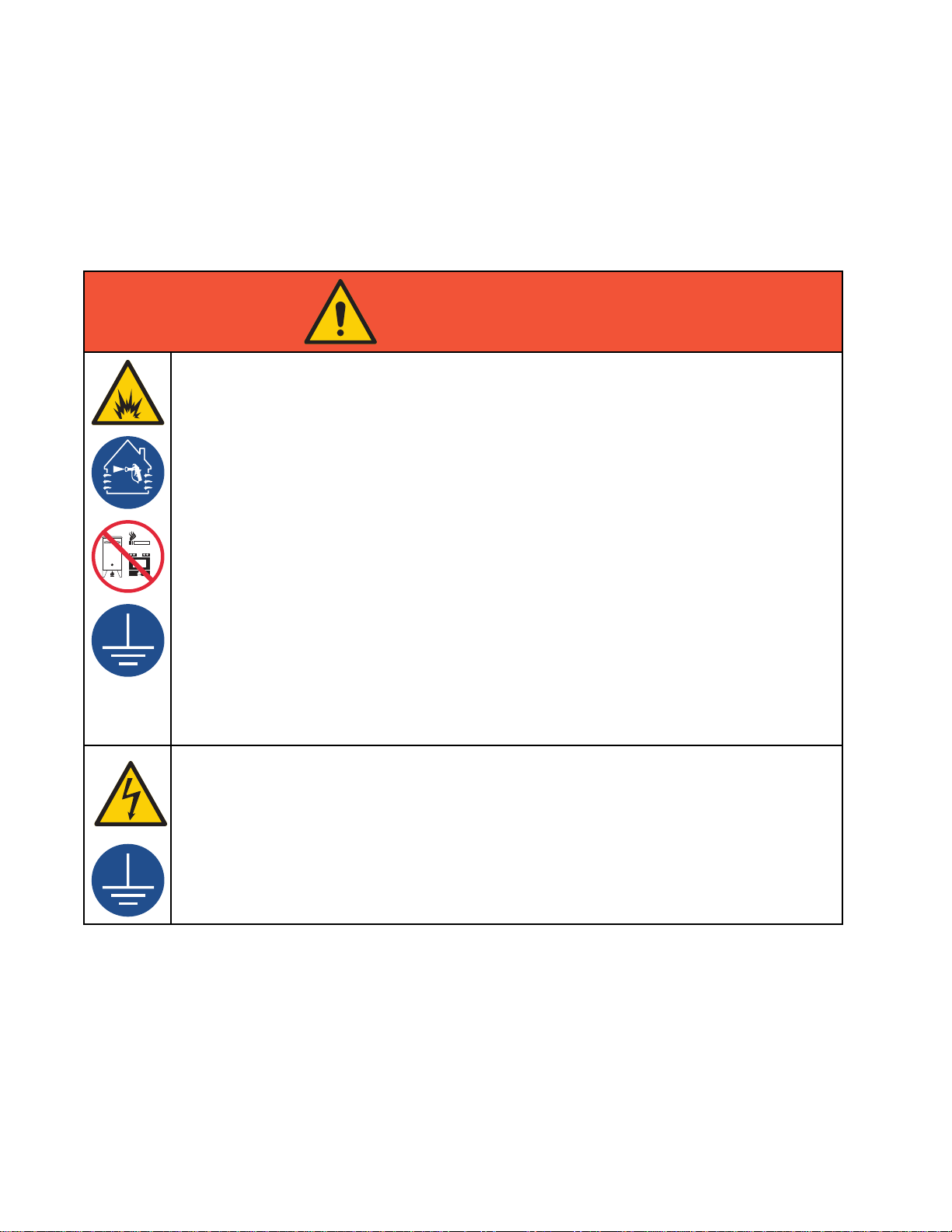
Warnings ........................................................... 6
Important Isocyanate (ISO) Information................ 9
Important Acid Catalyst Information ..................... 11
Acid Catalyst Conditions............................... 11
Moisture Sensitivity of Acid Catalysts ............ 12
System Control Drawing 16P577 ......................... 13
Configuring Your System .................................... 15
1. Select a Base Model ................................ 15
2. Select Hoses ........................................... 20
3. Select Mixing Option ................................ 22
4. Select a Spray Gun.................................. 23
5. Select Color and Catalyst Change
Kits................................................ 24
6. Select Pump Expansion Kits ..................... 25
7. Select Communication Options ................. 25
General Information ............................................ 26
Location............................................................. 26
Install the Display Module.................................... 27
Install the Booth Control...................................... 28
Air Supply .......................................................... 29
Fluid Supply ....................................................... 31
Fluid Requirements ...................................... 31
Single Color Connections ............................. 32
Color Change Connections........................... 32
Solvent Connections .................................... 32
TSL Cup Kit........................................................ 33
Solvent Meter Accessory..................................... 36
Light Tower Accessory........................................ 36
Electrostatic Air Hose Quick Disconnect Kit
24S004................................................. 36
Electrical Supply................................................. 37
Electrical Requirements................................ 37
Electrical Connections.................................. 37
Grounding.......................................................... 38
Electrical Schematics.......................................... 41
Standard Models (MC1000, MC2000,
MC3000, MC4000) ......................... 41
Dual Panel Models (MC1002, MC2002,
MC4002)........................................ 47
Optional Cables and Modules ....................... 53
Dimensions ........................................................ 54
Notes ................................................................ 55
Technical Data ...................................................56
Related Manuals
Manual No. Description
3A2800 PD2K Proportioner Repair-Parts Manual, Manual Systems
332562 PD2K Proportioner Operation Manual, Manual Systems
3A4186 PD2K Dual Panel Proportioner Opertion Manual, Manual Systems
3A2801 Mix Manifold Instructions-Parts Manual
332339 Pump Repair-Parts Manual
332454 Color Change Valve Repair-Parts Manual
332455 Color Change Kits Instructions-Parts Manual
332456 3rd and 4th Pump Kits Instructions-Parts Manual
334512 PD1K Pump Expansion Kits Instructions-Parts Manual
3A4497 Air Control Box Kit Instructions Manual
2332457H