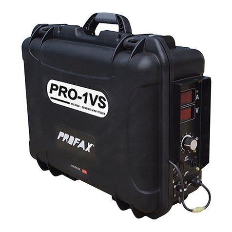
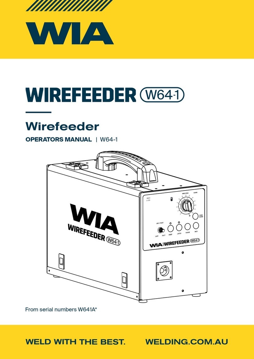
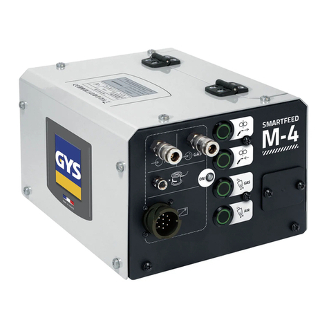
PROFAX PX20-TIG User manual

TABLE OF CONTENS
ARC WELDING SAFETY PRECAUTIONS ................................................................................i
SECTION 1 --SAFETY INFORMATION ....................................................................................1
SECTION 2 -- SPECIFICATIONS..............................................................................................1
SECTION 3 -- INSTALLATION..................................................................................................1
3 - 1. Wirefeeder........................................................................................................................................... 1
3 - 2. Feed Pen connections .........................................................................................................................2
3 - 3. Rear Panel ........................................................................................................................................... 2
3 - 4. Wire spoolinstallation ..........................................................................................................................3
3 - 5. Weldingwireinstallation....................................................................................................................... 3
SECTION 4 -- OPERATION...................................................................................................... 5
SECTION 5 -- MAINTENANCE AND TROUBLESHOOTING ..................................................6
5 - 1. RoutineMaintenance............................................................................................................................ 6
5 - 2. Troubleshooting.................................................................................................................................................6
5 - 3. Overloadprotection .....................................................................................................................................6
WARRANTY POLICY

ARC WELDING SAFETY PRECAUTIONS
ELECTRIC SHOCK can kill.
Touching live electrical parts can cause fatal shocks
or severe burns. The electrode and work circuit is
electrically live whenever the output is on. The input
power circuit and machine internal circuits are also
live when power is on. In semiautomatic or automatic
wire welding, the wire, wire reel, drive roll housing,
and all metal parts touching the welding wire are electrically live.
Incorrectly installed or improperly grounded equipment is a hazard.
1.- Do not touch live electrical parts.
2.- Wear dry, hole-free insulating gloves and body protection.
3.- Insulate yourself from work and ground using dry insulating
mats or covers.
4.- Disconnect input power or stop engine before installing or
servicing this equipment.
5.- Properly install and ground this equipment according to this
owner's manual and national, state, and local codes.
6.- Turn off all equipment when not in use.
7.- Do not use worn, damaged, undersized, or poorly spliced cables.
8.- Do not wrap cables around your body.
9.- Ground the workpiece to a good electrical (earth) ground.
10.- Do not touch electrode while in contact with the work (ground)
circuit.
11.- Use only well-maintained equipment. Repair or replace damaged
parts at once.
12.- Wear a safety harness to prevent falling if working above floor
level.
13.- Keep all panels and cover securely in place.
ARC RAYS can burn eyes and skin;
NOISE can damage hearing.
Arc rays from the welding process produce intense
heat and strong ultraviolet rays that can burn eyes and
skin. Noise from someprocesses candamagehearing.
1.- Wear a welding helmet fitted with a proper shade of
filter (see ANSIZ49.1 listed in Safety Standards) to protect your face
and eyes when welding or watching.
2.- Wear approved safety glasses. Side shields recommended.
3.- Use protective screens or barriers to protect others from flash and
glade; warn others not to watch the arc.
4.- Wear protective clothing made from durable, flame- resistant mate
rial (wool and leather) and foot protection.
5.- Use approved ear plugs or ear muffs if noise level is high.
FUMES AND GASES can be hazardous
to your health.
Welding produces fumes and gases. Breathing these
fumes and gases can be hazardous to your health.
1.- Keep your head out of the fumes. Do not breath the fumes.
2.-If inside, ventilatethe areaand / or use exhaust at the arc toremove
welding fumes and gases.
3.- If ventilation is poor, use an approved air-supplied respirator.
4.- Read the Material Safety Data Sheets (MSDSs) and the
manufacturer´s instruction for metal, consumables, coatings, and
cleaners.
5.-Work ina confinedspaceonlyif it is well ventilated, or whilewearing
an air-supplied respirator. Shielding gases used for welding can
displaceaircausinginjuryor death.Besurethebreathingairis safe.
6.- Do not weld in locations near degreasing, cleaning, or spraying
operations. The heat and rays of the arc can react with vapors to
form highly toxic and irritating gases.
7.-Donotweldoncoatedmetals,suchas galvanized,lead,orcadmium
plated steel, unless the coating is removed from the weld area, the
area is well ventilated, and if necessary, while wearing an air-
supplied respirator. The coatings and any metals containing these
elements can give off toxic fumes if welded.
WELDING can cause fire or explosion.
Sparks and spatter fly off from the welding arc. The
flyingsparksandhotmetal,weldspatter,hotworkpiece,
andhot equipmentcancausefiresandburns.
Accidentalcontact of electrode orwelding wire to
metal objects can cause sparks, overheating, or fire.
1.- Protect yourself and others from flying sparks and hot metal.
2.- Do not weld where flying sparks can strike flammable material.
3.- Remove all flammables within 35ft (10.7 m) of the welding arc. If
this is not possible, tightly cover them with approved covers.
4.- Be alert that welding sparks and hot materials from welding can
easily go through small cracks and openings to adjacent areas.
5.- Watch for fire, and keep a fire extinguisher nearby.
6.- Be aware that welding on a ceiling, floor, bulkhead, or partition can
cause fire on the hidden side.
7.- Do not weld on closed containers such as tanks or drums.
8.- Connect work cable to the work as close to the welding areas as
practical to prevent welding current from traveling long, possibly
unknown paths and causing electric shock and fire hazards.
9.- Do not use welder to thaw frozen pipes.
10.- Remove stick electrode from holder or cut off welding wire at
contact tip when not in use.
11.- Wear oil-free protective garments such as leather gloves, heavy
shirt, cuff less trousers, high shoes, and a cap. i
WARNING
ARC WELDING can be hazardous.
PROTECTYOURSELFANDOTHERSFROMPOSSIBLESERIOUSINJURYORDEATH.KEEPCHILDRENAWAY.PACEMAKERWEARERSKEEP
AWAYUNTIL CONSULTING YOURDOCTOR.
In welding, as in most jobs, exposure to certain hazards occurs. Welding is safe when precautions are taken. The safety information given
below is only a summary of the more complete safety information that will be found in the Safety Standards. Read and follow all Safety
Standards.
HAVE ALL INSTALLATION, OPERATION, MAINTENANCE, AND REPAIR WORK PERFORMED ONLY BY QUALIFIED PEOPLE.

FLYING SPARK AND HOT METAL can
cause injury
Chipping and grinding cause flying metal . As welds
cool, they can throw off slag.
1.- Wear approved face shield or safety goggles. Side shields
recommended.
2.- Wear proper body protection to protect skin.
CYLINDERS can explode if damaged. 4.- Never allow a welding electrode to touch any cylinder.
5.- Use only correct shielding gas cylinders, regulators, hoses, and
Shieldinggascylinderscontaingasunderhighpressure. fittings designed for the specific application; maintain them and
Ifdamaged,acylindercanexplode.Sincegascylinders associated parts in good condition.
are normally part of the welding process, be sure to 6.- Turn face away from valve outlet when openingcylinder valve.
treat them carefully. 7.- Keep protective cap in place over valve except when cylinder is in
use or connected for use.
1.- Protect compressed gas cylinders from excessive heat, mechanical 8.-Readandfollowinstructionsoncompressedgascylinders,associated
shocks, and arcs. equipment, and CGA publication P-1 listed in Safety Standards.
2.- Install and secure cylinders in an upright position by chaining them
to a stationary support or equipment cylinder rack to prevent falling
or tipping.
3.- Keep cylinders away from any welding or other electrical circuits.
WARNING
ENGINES
can
be
hazardous.
ENGINE EXHAUST GASES can kill. 2.- If usedin a closed area, vent engine exhaust outside andawayfrom
any building air intakes.
Engines produce harmful exhaust gases.
1.- Use equipment outside in open, well-ventilated
areas.
ENGINE FUEL can cause f i re or
explosion.
Engine fuel is highly flammable.
1.- Stop engine before checking or adding fuel.
2.- Do not add fuel while smoking or if unit is near any sparks or open
flames.
3.- Allw engine to cool before fueling. If possible, check and add fuel
to cold engine before beginning job.
4.- Do not overfill tank - allow room for fuel to expand.
5.- Do not spill fuel. If fuel is spilled, clean up before starting engine.
MOVING PARTS can cause injury. 4.- To prevent accidental stating during servicing, disconnect negative
(-) battery cable from battery.
Moving parts, such as fans, rotors, and belts can cut 5.-Keep hands, hair, loose clothing, andtools away from moving parts.
fingers and hands and catch loose clothing. 6.-Reinstallpanelsorguardsandclosedoorswhenservicingisfinished
and before starting engine.
1.- Keep all doors, panels, covers, and guards closed
and securely in place.
2.- Stop engine before installing or connecting unit.
3.-Haveonlyqualifiedpeopleremoveguardsorcoversformaintenance
and troubleshooting asnecessary.
SPARKS can cause BATTERY GASES 2.- Stop engine before disconnecting or connecting battery cables.
TO EXPLODE; BATTERYACID can 3.- Do not allow tools to cause sparks when working on a battery.
burn eyes and skin. 4.- Do not use welder to charge batteries or jump start vehicles.
5.- Observe correct polarity (+ and -) on batteries.
Batteries contain acid and generate explosive gases.
1.-Always wear a face shield when working on a
battery.
STEAM AND PRESSURIZED HOT
COOLANT can burn face, eyes, and
skin.
The coolant in the radiator can be very hot and under
pressure.
1.-Do not removeradiatorcapwhenengineis hot. Allowenginetocool.
2.- Wear gloves and put a rag over cap area when removing cap.
3.- Allow pressure to escape before completely removing cap.
ii

WARNING
WARNING statements identifyproceduresorpracticeswhich must befollowed to
avoid serious personal injury or loss of life.
4
3
When changing wire size or type; check drive rolls
and wire guide size.
1. PRESSURE ARM ADJUSTMENT KNOB
2. INLET WIRE GUIDE
3. DRIVE ROLL RETAINER
4. DRIVE ROLL
5. PRESSURE ARM
6. FEED PEN SECURING KNOB
6
5
1
2
SECTION 1 SAFETY SIGNAL WORDS
The following safety alert symbol and signal words are used throughout this manual to call
attention to and identify different levels of hazard and special instructions.
IMPORTANT: Statements identify special instructions necessary for the most efficient operation of
this equipment. SECTION 2 SPECIFICATIONS
TABLE 2-1 TECHNICAL SPECIFICATIONS
Specifications
Description
Input power:
Duty Cycle:
Wire feed speed range:
Wire diameter range:
Input power cord:
Overall dimensions:
Weight:
Single phase, 115VAC, 3A, 50/60Hz.
100% Duty cycle.
75 to 900 IPM (1.9 to 23 m/min)
0.023 to 5/64" (0.6 to 2.0mm)
10 Ft (3 M).
Depth: 25-1/2" (648mm); Width: 11" (280mm); Height: 14" (356mm).
Net: 36 lb. (16.5 Kg)
SECTION 3 INSTALLATION
3-1 WIRE FEEDER
WARNING
ELECTRIC SHOCK can kill; ARCING can damage unit. MOVING PARTS can
cause injury.
FIGURE 3-1 WIRE FEEDER 1
CAUTION
CAUTION statements identify procedures orpractices which must be followed to
avoid minor personal injury or damage to this equipment.

3-2 FEED PEN CONNECTIONS
WARNING
ELECTRIC SHOCK can kill; MOVING PARTS can cause injury.
1
4
PX20-TIG
TIG COLD WIRE FEED SYSTEM
2
3
Turn off and disconnect wire feeder, open wire feeder door.
1. ACCESS HOLE FOR FEED PEN CONNECTION.
2. FEED PEN INLET GUIDE. Loosen securing knob and
insert feed pen into block fully. Tighten securing knob.
3. TRIGGER PLUG.
4. TRIGGER RECEPTACLE. Insert plug into receptacle and
tighten threaded collar.
Close and latch door.
FIGURE 3-2 FEED PEN AND TRIGGER LEAD CONNECTIONS
3-3 REAR PANEL
FIGURE 3-3 REAR PANEL UNIT
2
Switch S1
Wire Inlet Guide
Fuse F1
115VAC POWER CORD

1
2
5
1.- WIRE SPOOL / REEL
2.- WELDING WIRE
3.- WIRE INLET INSULATOR
4.- WIRE INLET GUIDE
5.-PRESSURE ARM ADJUSTMENT KNOB
6.- DRIVE ROLL
3
4
6
2
1
3
For 8" and 12" standard wire spools. If
necessary, move hub on support for use with
different size wire spool.
1. Spool hub
2. Spool locating pin
3. Wire spool / reel
4. Spool hub cap
Turn the spool hub cap counter clockwise to
remove it. Install the wire spool, ensure the
spool hub pin enters one of the holes of the
wire spool. Reinstall the spool hub cap.
4
3-4 WIRE SPOOL INSTALLATION
FIGURE 3-4 WIRE SPOOL INSTALLATION.
3-5 WELDING WIRE INSTALLATION
WARNING
SEE SAFETY PRECAUTIONS AT BEGINNING OF MANUAL FOR
BASIC WELDING INFORMATION.
3

HOLD WIRE TIGHTLY TO PREVENT
UNRAVELING
Open pressure arm
assembly.
Hold wire tightly and cut off
end. Feed wire through guide
into feed pen. Continue to
hold wire.
WOOD
To adjust drive roll pressure, press trigger
to feed wire against wood surface and
adjust knob so wire does not slip.
Cut off excess wire.
Close and latch door.
4
POWER
ON
OFF
Close and latch
pressure arm assembly.
Turn on wire feeder.

CAUTION
SEE SAFETY SIGNAL AT THE BEGINING
OF THIS MANUAL
Place the switch in ON position to turn wire feeder on.
Place the switch in OFF position to turn wire feeder off.
1 - WIRE FEED SPEED CONTROL.
40
50
60
30
70
1
Use this control to set wire feed speed. Turn clockwise
to increase speed. The numbers are a reference with
respect to a maximum rated wire feed of 900ipm.
20
80
10
90
0
100
SECTION 4 OPERATION
4-1 CONTROLS
FIGURE 4-1 CONTROLS
FIGURE 4-2 INPUT POWERSWITCH
FIGURE 4-3 WIRE SPEEDCONTROL
5
PX20-TIG
TIG COLD WIRE FEED SYSTEM
WIRE SPEED CONTROL
FEED PEN INPUT
TRIGGER
RECEPTACLE

SECTION 5 MAINTENANCE AND
TROUBLESHOOTING
5-1 ROUTINE MAINTENANCE
TIME
MAINTENANCE
3 MONTHS
Check all labels. Repair or replace any damaged cables and feed pen. Clean and tighten all weld
cable connections. More than normal use: (see 6 month entry)
6 MONTHS
Clean drive rolls. Blow out or vacuum inside. Clean all rotating parts. During heavy service, clean
monthly.
5-2 TROUBLESHOOTINGS
TROUBLE
No wire feed
PROBABLE CAUSE
Power switch is off on wire feeder.
REMEDY
Turn power switch on.
F1 fuse open.
Replace F1 fuse.
Connection at power receptacle.
Check and repair power connection.
Feed pen trigger circuit.
Repair trigger, plug or wiring in feed pen.
Motor or control board PC1.
Have authorized repair agent diagnose.
Erratic wire feed
Drive roll pressure or spool hub tension
Readjust drive roll pressure and hub tension.
Drive rolls size.
Change to correct drive roll size.
Worn or dirty drive rolls.
Clean or replace drive rolls.
Weld spatter on tip.
Clean or replace tip.
Dirty contact tip or liner.
Motor or control board PC1.
Replace contact tip and liner.
Have authorized repair agent diagnose.
5-3 OVERLOAD PROTECTION
WARNING
SEE SAFETY SIGNAL AT THE BEGINNING OFTHIS MANUAL
2
Turn off power source and disconnect wire
feeder before proceeding.
1
Fuse F1 (10 amp) protects wire feeder from
overload. Incorrect fuse size can damage unit.
Be sure to select correct fuse size and
capacity.
1 - FUSE COVER. Remove fuse cover.
2 - FUSE F1 (10 Amp)
FIGURE 5-1 OVERLOAD PROTECTION 6

PROFAX
1603 North Main Street
Pearland Tx 77581
Phone: 281-485-6258
WARRANTY
LIMITED WARRANTY - Subject to the terms and conditions stated below,
PROFAX,
Pearland, TX warrants it's products to be free from defects in material and/or workmanship at
the time of delivery by
PROFAX.
PROFAX
willhonorwarrantyclaimsonproductsproventohavefailedfromadefectinmaterialand/or
workmanship, forthe appropriate time period aslisted below, beginning fromthe distributor's date of sale
totheoriginalenduser. Forwarrantytoapply,productsmustbesoldbythedistributor
within 1 year
fromtheoriginaldateofsaletothedistributor.Productswillnotbecoveredifdamageisdeterminedtobe
caused bymisuse, neglectand/orabuse.
Consumableproductsmanufacturedby
PROFAX.............................................................
30 Days
Contactors,Meters,FanMotors,Rheostats,Diodes,
&
Brushes.................................................
*OMW
FluxCoredGuns, MIGGuns
&
SpoolGuns...................................................................
90 Days
Arc Gouging Torches, Plasma Torches, TIG Torches &CO2Heaters.............................................90 Days
Control, Extensions, Interconnect and Adapter Cords, Plugs
&
Connectors...................................90 Days
Esab®,Lincoln®,Miller®,andPROFAXDriveRolls.................................................................
90 Days
Remote Fingertip, Hand andFoot Controls .....................................................................................90 Days
Slides, Oscillators, & Track CuttingMachine/Beveling Machine......................................................90 Days
Turning Rolls, Welding Positioners, and Manipulators ...................................................................... 1 Year
Spool Gun Controls, Pro II TIG, & Flowmeter/Regulator .................................................................. 1 Year
WireFeeders
&
PowerSources.................................................................................................
3Year
Uponreturnoftheproduct,atuser'sexpense,
PROFAX
reservestherighttoeitherrepairorreplacethe
productasnecessary. Thisistheonlywarrantyeitherexpressedorimplied.
*OMW - Original Manufacturer's Warranty
Table of contents
Other PROFAX Wire Feeder manuals