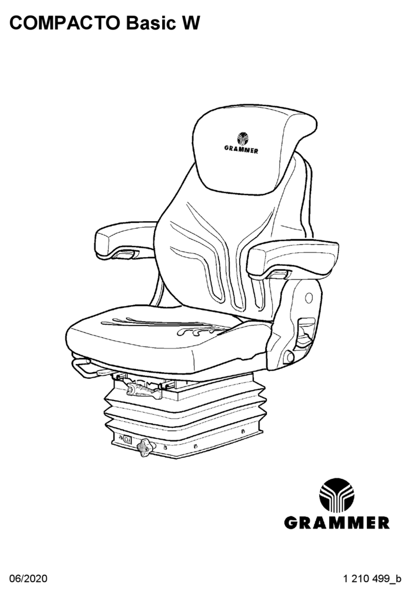
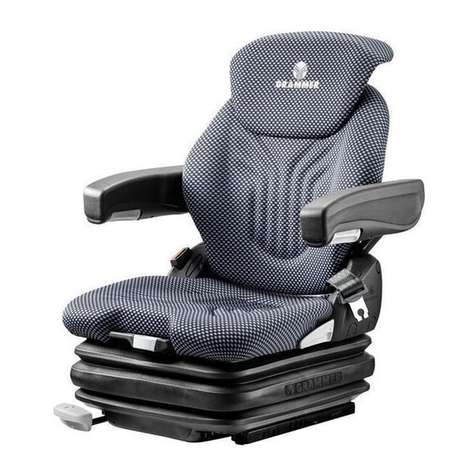
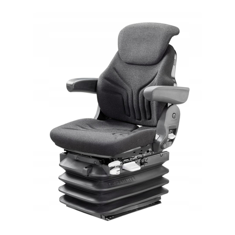
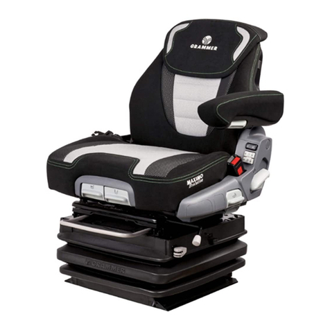
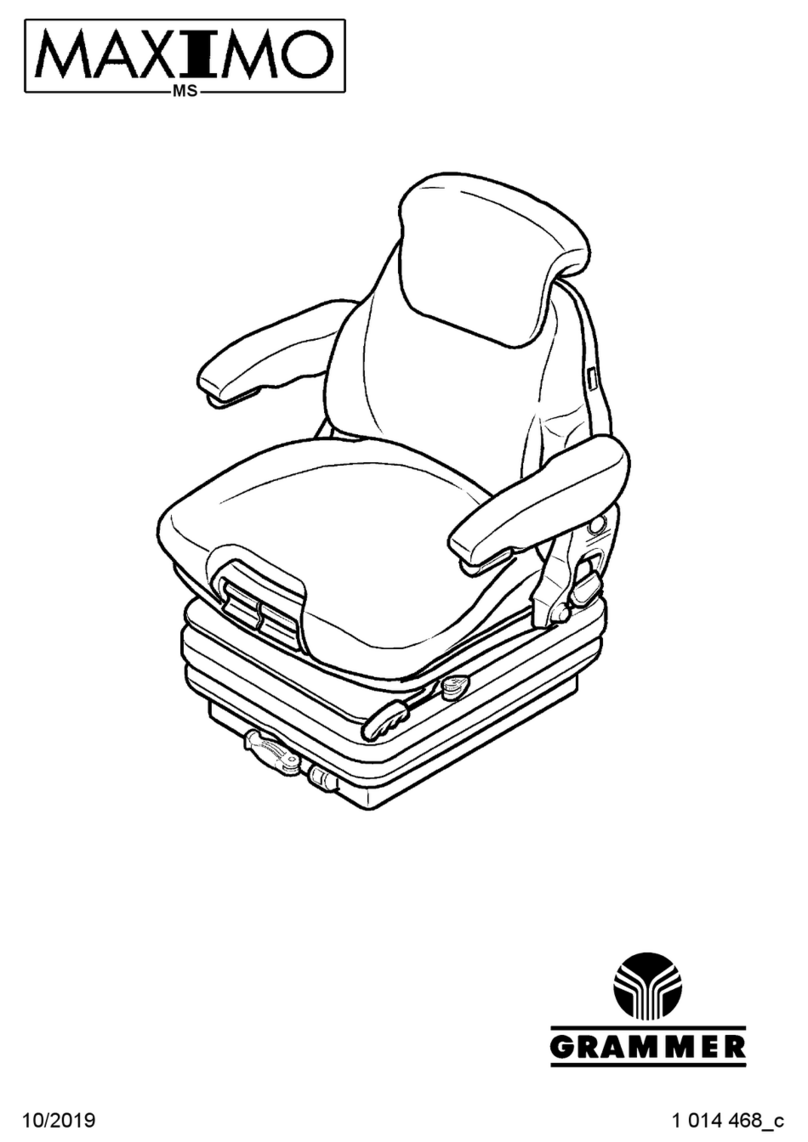
Grammer MSG97GL Operating instructions

October 2012
Material no. 1 263 118
Repair manual GRAMMER seat suspension MSG97GL
Page 1 of 1
TABLE OF CONTENTS
Preface
1 Description
1.1 Safety instructions
1.2 Rating plate
2 Diagnosis
2.1 Overview of components
2.2 Overview of faults – Pointing out possible faults that might occur
2.3 Troubleshooting – Locating the fault
3 Repair work
3.1 Top cover – removal and installation
3.2 Covers on the right and left side – removal and installation
3.3 Bellows – removal and installation
3.4 Vertical shock absorber – removal and installation
3.5 Longitudinal horizontal shock absorber – removal and installation
3.6 Fore/aft isolator unit – removal and installation
3.7 Locking mechanism for fore/aft isolator – removal and installation
3.8 Compressor – removal and installation
3.9 Level indicator – removal and installation
3.10 Compressed-air hose – removal and installation
3.10.1 Compressed-air hose between compressor and air spring – removal and
installation
3.10.2 Compressed-air hose between air spring and additional air supply – removal
and installation
3.10.3 Compressed-air hose between additional air supply and valve for height
adjustment – removal and installation
3.11 Air spring – removal and installation
3.12 Additional air supply – removal and installation
3.13 Holder for height adjustment – removal and installation
3.14 Cable harness for seat suspension – removal and installation
3.15 Upper part of suspension – removal and installation
3.16 Lower part of suspension – removal and installation
3.17 Worn parts – replacement

Repair manual GRAMMER seat suspension MSG97GL – October 2012
Material no. 1 263 118
Preface
Page 1 of 2
Notes on these instructions
This repair manual includes information and instructions on how to perform repair
work on the seat suspension MSG97GL of GRAMMER seats.
The repair of the upper seat part is described in the respective repair manual for the
upper seat part to which a reference is made, if required (see repair manual for
upper seat part).
Example:
Remove the cable of the seat occupancy detection system at the upper seat part
(see repair manual for upper seat part).
The seat suspension MSG97GL with holder on the left forms the basis for
illustrations in this repair manual. In the case of technical deviations in work
procedures (due to different seat suspension designs), refer to the current text or
individual chapters of the manual.
Each chapter starts with a list of all preparatory work to be completed before starting
the repair. These preparations are described in separate chapters and shall be
carried out without the preparatory steps described there.
For spare part orders, please use the numbers stated in the latest issue of the
relevant spare parts catalogue.
The description of the work procedures refers to the removed seat suspension and
the dismounted upper part of seat.
Depending on the individual installation situation, some work may also be performed
on the installed seat suspension and/or with upper seat part. For this reason, check
the environment of the installed seat suspension for this possibility before starting
work. The safety instructions of the specific vehicle manufacturer and those stated
in chapter 1 of this repair manual must be strictly observed.
This repair manual also includes some information on delivery options, if these
require further explanation. Since the scope of delivery depends on the specific
customer order, the actual seat suspension design may deviate from the
descriptions and illustrations in this manual.
The illustrated repair steps refer to the seat suspension for left-hand drive. Different
work steps are to be performed laterally reversed when repairing vehicle models
with right-hand drive.
If not stated otherwise, the directional indications "front, back" and "right, left" refer
to the installed seat suspension regarded in the driving direction of the vehicle.
The document layout is suitable for later use of this repair manual via CD-ROM /
INTERNET / INTRANET.
Basic information on the seat suspension
The removal and installation of the seat suspension are described in the repair
manual for the upper seat part.
Note:
For the removal and installation of the seat suspension at the vehicle, ask the
vehicle manufacturer for the necessary assembly work to be carried out.
The seat suspension is provided with a long-lasting lubrication (approx. 10 years).
The lubricating points must be re-greased only after repair work, using an acid-free
multi-purpose lubricant.
In the description of the present repair manual, not all fastening parts might be
mentioned. After repair, it might be necessary to check fastening parts regarding
their factory-made laying, support and securing and to correct them respectively, if
required.

Repair manual GRAMMER seat suspension MSG97GL – October 2012
Material no. 1 263 118
Preface
Page 2 of 2
Cables and air hoses may only be fastened with cable ties at the defined spots by
hand (loose). Make sure that cables and air hoses cannot be squeezed or distorted
when the seat suspension is adjusted and the seat moved.
Replace all removed old parts with enclosed new ones. If there is no new part
included, the old one is to be cleaned and checked for its suitability for re-use.
Defective parts and worn parts must be replaced by new ones.
GRAMMER AG rejects any warranty claims if damaged or worn parts and
assemblies are not replaced by spare parts released by GRAMMER AG.
Qualified personnel
These instructions offer basic information on proper technical seat repair. The
contents of the work procedures described are intended for professionally educated
technicians with profound product knowledge. This level of knowledge is an
imperative requirement when performing the work and procedures described in this
document.
In order to avoid bodily injury, reduced operational safety of the seat suspension or
damage to it resulting from improperly performed work, all information and
instructions, in particular the safety instructions stated in Chapter 1, must be read
carefully and strictly observed.
As an inevitable matter of fact, GRAMMER AG cannot evaluate all situations and
consequences that may bear a risk of injury for the persons involved in the
described work procedures. For this reason it is absolutely necessary that every
person who carries out repair work at the seat suspension uses his/her professional
knowledge to make sure that his/her own safety will not be put at risk and that the
selected type of repair will not cause any negative effects, in particular with regard
to technical safety.
For this reason, GRAMMER AG disclaims liability for any possible damage of this
kind.
We point out explicitly that all work steps and procedures described are to be
performed with consideration to the applicable directives and regulations stipulated
by the relevant local authorities and in compliance with the provisions on health
protection, prevention of accidents and environmental protection.
Change notification and copyright
The seat suspensions are subject to continuous development. Please understand
that we must reserve the right to make changes in shape, equipment and technical
design. For this reason, the contents of this repair manual cannot be used to
substantiate any possible claims.
Reprint, translation and copies of this manual or parts thereof are admissible only
after written approval.
GRAMMER AG ⋅Postfach 14 54
D-92204 Amberg
Phone +49 (0) 96 21 / 66-6822
www.grammer.com
Delivery and factory address:
GRAMMER AG
Köferinger Str. 9-13
D-92245 Kümmersbruck

Repair manual GRAMMER seat suspension MSG97GL – October 2012
Material no. 1 263 118
1 Description
Page 1 of 1
TABLE OF CONTENTS
1.1 Safety instructions
1.2 Rating plate
Note:
Please refer to the applicable seat operating instructions for further details.

Repair manual GRAMMER seat suspension MSG97GL – October 2012
Material no. 1 263 118
1.1 Safety instructions
Page 1 of 1
1 All inspection, test and repair work must be performed exclusively by adequately
trained personnel.
2 All work steps and procedures described are to be performed with consideration
to the applicable directives and regulations stipulated by the relevant local
authorities and in compliance with the provisions on health protection,
prevention of accidents and environmental protection.
3 Special notes in this repair manual are highlighted as follows:
WARNING ...
indicates possible risks for persons and their prevention.
ATTENTION ...
indicates possible damage or deterioration of material and its prevention.
Note: …
introduces an additional explanation for better understanding of the work to be
carried out.
Installation note: ...
introduces an additional explanation for better understanding of the installation
work to be carried out.
4 Before starting repair work, the following work has to be carried out:
•Disconnect the seat suspension from the power supply.
•Move the seat suspension to the end stops of the lower position.
5 When using oil, grease and other chemical substances, the relevant safety
regulations for the handling and use of these products must be observed.

Repair manual GRAMMER seat suspension MSG97GL – October 2012
Material no. 1 263 118
1.2 Rating plate
Page 1 of 1
The rating plate is located on the back of
the top cover of the seat suspension.
The rating plate shows the following
information (example):
(A) Country of manufacture = MADE IN
XXXXXXX
(B) DESIGNATION = MSG97GL/731 12V
(C) INVENTORY NO. = 1237555
(D) Year / CW / Assembly
12 03 141:
•Year of manufacture = 12 (2012)
•Built in week = 03 (Jan)
•Assembly = 141
(E) ORDER NO. = XX 96586990020
•Country indicator = XX
Note:
When orders are placed, the correct
INVENTORY NO. (C) on the rating plate is
always to be quoted.

Repair manual GRAMMER seat suspension MSG97GL – October 2012
Material no. 1 263 118
2 Diagnosis
Page 1 of 1
TABLE OF CONTENTS
2.1 Overview of components (pages 1-4)
●Pneumatic modules and connecting diagram (page 1)
●Compressor, compressor cable and pin assignment (page 2)
●Cable harness of seat suspension and pin assignment (pages 3-4)
2.2 Overview of faults – Pointing out possible faults that might occur
(pages 1-2)
2.3 Troubleshooting – Locating the fault (pages 1-7)
1 Inspection of compressor and current path (compressor cable) (pages 1-
2)
2 Inspection of the micro-switch (page 3)
3 Inspection of the cable harness for seat suspension (pages 4-6)
4 Inspection of the pneumatic air system (page 7)

Repair manual GRAMMER seat suspension MSG97GL – October 2012
Material no. 1 263 118
2.1 Overview of components
Page 1 of 4
Pneumatic modules and
connecting diagram
(1) Additional air supply
ATTENTION Damage!
Please observe the notes stated in
Chapter 3.12 when pulling off the
compressed-air hose (2 and 3) at
the connection of the additional air
supply (1).
(2) Compressed-air hose between air
spring (7) and additional air supply
(1)
(3) Compressed-air hose between
additional air supply (1) and valve
for height adjustment (4)
(4) Valve for height adjustment
ATTENTION Damage!
Please observe the notes stated in
Chapter 3.13 when pulling off the
compressed-air hose (3) at the
connection of the height adjustment
valve (4).
(5) Compressed-air hose between
compressor (6) and air spring (7)
(6) Compressor
ATTENTION Damage!
Please observe the notes stated in
Chapter 3.8 when pulling off the
compressed-air hose (5) at the
connection of the compressor (6).
(7) Air spring
1
3
3
5
6
43
2
22
7
2811

Repair manual GRAMMER seat suspension MSG97GL – October 2012
Material no. 1 263 118
2.1 Overview of components
Page 2 of 4
Compressor, compressor cable
and pin assignment
(1) Plug of cable harness for seat
suspension
(4-pin)
(2) Pin assignment for compressor (8)
at the plug (1)
Pin:
P3 (voltage)
P4 (ground)
(3) Cable between compressor (8) and
micro-switch (5)
(4) Cable to plug (1)
(5) Micro-switch
(6) Plug (blue and red lines)
(7) Socket (blue and red lines)
(8) Compressor
(9) Right-angle plug (blue line)
voltage at the compressor
(10) Right-angle plug (black line)
ground at the compressor
Electrical plug and socket connections:
(A) Electrical connection (blue line)
between right-angle plug (9) and
compressor (8)
(B) Electrical connection (black line)
between right-angle plug (10) and
compressor (8)
(C) Electrical connection (blue and red
lines)
(E) Electrical connection (4-pin)
between cable harness plug for seat
suspension (1) and cable harness
socket for vehicle connection
Line colours:
bl = blue
ro = red
sw = black
P1
P2
P4
P3
8
10
4
sw
bl
9
A
B3
bl
ro
sw
4
5
1
5
6
1
3
1
C
2
7
E
2816

Repair manual GRAMMER seat suspension MSG97GL – October 2012
Material no. 1 263 118
2.1 Overview of components
Page 3 of 4
Cable harness for seat
suspension and pin assignment
(1) Pin assignment for seat occupancy
detection system at the cable
harness plug for seat suspension (3)
Pin:
P1 (signal A)
P2 (signal B)
(2) Pin assignment for voltage supply at
the cable harness plug for seat
suspension (3)
Pin:
P3 (voltage for compressor and
additional load)
P4 (ground for compressor and
additional load)
(3) Plug of cable harness for seat
suspension
(4-pin)
(4) Plug of cable harness for seat
suspension
(8-pin)
(5) Cable harness for seat suspension
(6) Plug (blue and red lines)
to plug of micro-switch
(7) Right-angle plug (blue line)
voltage at the compressor
(8) Right-angle plug (black line)
ground at the compressor
(9) Pin assignment for seat occupancy
detection system at the cable
harness plug for seat suspension (4)
Pin:
P1 (signal B)
P4 (signal A)
(10) Pin assignment for lumbar support
at the cable harness plug for seat
suspension (4)
Pin:
P6 (ground) and
P7 (voltage)
(11) Pin assignment for heater at the
cable harness plug for seat
suspension (4)
Pin:
P6 (ground) and
P8 (voltage)
(12) Pin assignment for climate control
system at the cable harness plug for
seat suspension (4)
Pin:
P3 (voltage) and
P6 (ground)
(13) Pin assignment for micro-switch at
the plug (6)
Pin:
Blue line (voltage)
Red line (voltage)
(14) Cable harness to the compressor
AB
C
D
C
E
13
6
2817
11 10
12
P4P5P6P7P8
P1P2P3
4
9
P1
P2
P4
P3
23
1
14
4
6
8
7
5
3

Repair manual GRAMMER seat suspension MSG97GL – October 2012
Material no. 1 263 118
2.1 Overview of components
Page 4 of 4
Electrical plug and socket connections:
(A) Electrical connection (blue cable)
between right-angle plug (7) and
compressor
(B) Electrical connection (black cable)
between right-angle plug (8) and
compressor
(C) Electrical connection (blue and red
lines) between plug (6) and socket
of micro-switch
(D) Electrical connection (8-pin)
between cable harness plug for seat
suspension (4) and cable harness
socket for upper seat part
(E) Electrical connection (4-pin)
between cable harness plug for seat
suspension (3) and cable harness
socket for vehicle connection
AB
C
D
C
E
13
6
2817
11 10
12
P4P5P6P7P8
P1P2P3
4
9
P1
P2
P4
P3
23
1
14
4
6
8
7
5
3

Repair manual GRAMMER seat suspension MSG97GL – October 2012
Material no. 1 263 118
2.2 Overview of faults – Pointing out possible faults that might occur
Page 1 of 2
This chapter contains notes on possible faults of the seat suspension. These notes and the information provided in Chapter 2.3 "Troubleshooting" are intended to facilitate the
elimination of faults.
Faults caused due to insufficient maintenance or improper repair are not covered here.
Note: The components mentioned are illustrated in Chapter 2.1, if not stated otherwise in this text.
Fault description Possible cause Troubleshooting
Seat suspension does not respond when operating the handle
for height adjustment in upward direction.
• Compressor is not running.
• The right-angle plug at the micro-switch or compressor
is not connected correctly.
• Micro-switch is defective.
• No voltage.
Check the compressor / compressor cable (Chapter
2.3, inspection step no. 1.1).
Check the plug-in connectors and establish the
connection, if necessary.
Check the micro-switch (Chapter 2.3, inspection
step no. 2.1).
Check the cable harness for seat suspension
(Chapter 2.3, inspection step no. 3.1).
Seat suspension does not respond when operating the handle
for height adjustment in downward direction.
• Valve for height adjustment is defective.
• Compressed-air hose is bent.
Check pneumatic air system (Chapter 2.3,
inspection step no. 4.1).
Seat suspension changes its position while driving, deflates and
lowers down.
• Compressed-air hose connections are leaky.
• Compressed-air hoses are leaky.
• Air spring is leaky.
• Additional air supply is leaky.
• Valve for height adjustment is leaky.
• Compressor is leaky (return valve).
Check all compressed-air hose connections for air
leakage and, if necessary, seal leaky connections
professionally.
Check pneumatic air system (Chapter 2.3,
inspection step no. 4.1).
Replace air spring (see Chapter 3.11).
Replace additional air supply (see Chapter 3.12).
Replace height adjustment valve (see Chapter 3.13).
Replace compressor (see Chapter 3.8).

Repair manual GRAMMER seat suspension MSG97GL – October 2012
Material no. 1 263 118
2.2 Overview of faults – Pointing out possible faults that might occur
Page 2 of 2
Fault description Possible cause Troubleshooting
Height adjustment upwards:
compressor runs, but seat suspension is not lifted
• Air system is leaky.
• Compressor is defective, no power.
Check pneumatic air system (Chapter 2.3,
inspection step no. 4.1).
Check compressor (Chapter 2.3, inspection step no.
1.1).
Seat suspension moves up automatically (compressor does not
switch off).
• Micro-switch is defective.
• Cable-break or short-circuit
(e.g. caused by abrasion at the cable harness).
Check the micro-switch (Chapter 2.3, inspection
step no. 2.1).
Replace the cable harness of the seat suspension
(see Chapter 3.14).
Compressor is not running.
• No voltage at the compressor, compressor is
defective.
• Micro-switch is defective, cable-break.
Check the compressor / compressor cable (Chapter
2.3, inspection step no. 1.1).
Check the micro-switch (Chapter 2.3, inspection
step no. 2.1).
Seat suspension travels up and down and hits the upper and
lower end stops.
• Vertical shock absorber is defective.
• Height wrongly adjusted.
Replace the vertical shock absorber (see Chapter
3.4).
Adjust height correctly (see valid operating
instructions).

Repair manual GRAMMER seat suspension MSG97GL – October 2012
Material no. 1 263 118
2.3 Troubleshooting – Locating the fault
Page 1 of 7
Preconditions for fault diagnosis for each test:
•The individual functions are activated in compliance with the instructions of the seat operating instructions.
•The electrical system of the vehicle has been inspected and found to be OK in compliance with the vehicle operating instructions.
•Electrical connection at the components produced according to instruction and locked, if possible.
•Cable harness for seat suspension has been inspected with regard to arcing spots and broken leads (kinks) and found to be OK.
•Ignition switched off (no voltage that might cause a current flow must be applied to the seat suspension).
Note: The components mentioned are illustrated in Chapter 2.1, if not stated otherwise in this text.
Descriptions of the work required during the diagnosis can be found in Chapter 3.
1 Inspection of compressor and current path (compressor cable)
Preconditions for fault diagnosis:
•Micro-switch has been inspected and found to be OK.
•Pneumatic air system has been inspected and found to be OK.
•Bellows at the upper suspension part removed (see Chapter 3.3) and pressed down.
Step
no. Inspect/operate Result/specified status Troubleshooting
1.1 • Disconnect the electrical connection (E) between the cable
harness plug for seat suspension and the cable harness socket
for vehicle connection.
• Connect the multimeter to pins P3 and P4 in the cable harness
plug of the seat suspension (4-pin).
• Pull up the handle for height adjustment and measure the
resistance at the pins P3 and P4:
P3 ΩP4 = 1.5 Ω(±10%) (total resistance of compressor
cable, micro-switch and compressor)
Proceed with inspection step no. 1.4.
>> 1.5 Ω(→ ∞)(break) or
<< 1.5 Ω(→ 0)(short-circuit)
Proceed with inspection step no. 1.2.

Repair manual GRAMMER seat suspension MSG97GL – October 2012
Material no. 1 263 118
2.3 Troubleshooting – Locating the fault
Page 2 of 7
Step
no. Inspect/operate Result/specified status Troubleshooting
1.2 • Disconnect the electrical connection (A and B) between the
right-angle plugs (black and blue cables) and the compressor.
• Pull up the handle for height adjustment and measure the
resistance at the pins P3 and P4:
P3 ΩP4 = ∞ Ω(resistance of the line to the compressor) Proceed with inspection step no. 1.3.
<< ∞ Ω(→ 0)(short-circuit) Replace the cable harness of the seat
suspension (see Chapter 3.14).
1.3 • Bridge contacts of the right-angle plugs.
• Pull up the handle for height adjustment and measure the
resistance at the pins P3 and P4:
P3 ΩP4 << 1 Ω(resistance of the line to the compressor) Replace compressor (see Chapter 3.8).
>> 1 Ω(→ ∞)(break) Replace the cable harness of the seat
suspension (see Chapter 3.14).
1.4 • Re-establish electrical connection (E) and (A and B) if
necessary.
• Switch the ignition on.
• Pull up the handle for height adjustment.
Compressor is running and seat suspension
moves upwards.
Compressor is running and seat suspension does
not move upwards; compressor is leaky (return
valve).
End of inspection.
Replace the compressor (see Chapter
3.8).

Repair manual GRAMMER seat suspension MSG97GL – October 2012
Material no. 1 263 118
2.3 Troubleshooting – Locating the fault
Page 3 of 7
2 Inspection of the micro-switch
Preconditions for fault diagnosis:
•Bellows at the upper suspension part removed (see Chapter 3.3).
Step
no. Inspect/operate Result/specified status Troubleshooting
2.1 • Disconnect the electrical connection (C) (red and blue lines to
the micro-switch).
• Connect the multimeter to the pins of the red and blue lines in
the plug to the micro-switch and measure the resistance at the
pins:
red Ωblue = ∞ Ω(total resistance of the micro-switch and
lines)
Proceed with inspection step no. 2.2.
<< ∞ Ω(→ 0)(short-circuit) Micro-switch is defective.
Replace the holder for height adjustment
(see Chapter 3.13).
2.2 • Pull up the handle for height adjustment.
• Measure resistance at the pins of the red and blue lines:
red Ωblue = 0.5 Ω(±10%) (total resistance of the micro-
switch and lines)
End of inspection.
>> 0.5 Ω(→ ∞)(break) Micro-switch is defective.
Replace the holder for height adjustment
(see Chapter 3.13).

Repair manual GRAMMER seat suspension MSG97GL – October 2012
Material no. 1 263 118
2.3 Troubleshooting – Locating the fault
Page 4 of 7
3 Inspection of the cable harness for seat suspension
Preconditions for fault diagnosis:
•Upper seat part removed at the seat suspension.
•Micro-switch has been inspected and found to be OK.
•Compressor and current path have been inspected and found to be OK.
•Pneumatic air system has been inspected and found to be OK.
Step
no. Inspect/operate Result/specified status Troubleshooting
3.1 • Disconnect the electrical connection (E) between the cable
harness plug for seat suspension and the cable harness socket
for vehicle connection.
• Connect the multimeter to pins P3 and P4 in the cable harness
plug of the seat suspension (4-pin).
• Measure the resistance at the pins P3 and P4 in the cable
harness plug of the seat suspension (4-pin).
P3 ΩP4 = ∞ ΩProceed with inspection step 3.2.
<< ∞ Ω(→ 0)(short-circuit) Replace the cable harness of the seat
suspension (see Chapter 3.14).

Repair manual GRAMMER seat suspension MSG97GL – October 2012
Material no. 1 263 118
2.3 Troubleshooting – Locating the fault
Page 5 of 7
Step
no. Inspect/operate Result/specified status Troubleshooting
3.2 • Bridge the pins P6 and P8 in the plug of the cable harness for
the seat suspension (8-pin) (pin assignment for the heater).
• Measure the resistance at the pins P3 and P4 in the cable
harness plug of the seat suspension (4-pin).
P3 ΩP4 << 1 Ω(R→ 0) (pass) Proceed with inspection step no. 3.3.
>> 1 Ω(R→∞) (break) Replace the cable harness of the seat
suspension (see Chapter 3.14).
3.3 • Bridge the pins P6 and P7 in the plug of the cable harness for
the seat suspension (8-pin) (pin assignment for the lumbar
support).
• Measure the resistance at the pins P3 and P4 in the cable
harness plug of the seat suspension (4-pin).
P3 ΩP4 << 1 Ω(R→ 0) (pass) Proceed with inspection step no. 3.4.
>> 1 Ω(R→∞) (break) Replace the cable harness of the seat
suspension (see Chapter 3.14).
3.4 • Bridge the pins P3 and P6 in the plug of the cable harness for
the seat suspension (8-pin) (pin assignment for the climate
control system).
• Measure the resistance at the pins P3 and P4 in the cable
harness plug of the seat suspension (4-pin).
P3 ΩP4 << 1 Ω(R→ 0) (pass) Proceed with inspection step no. 3.5.
>> 1 Ω(R→∞) (break) Replace the cable harness of the seat
suspension (see Chapter 3.14).

Repair manual GRAMMER seat suspension MSG97GL – October 2012
Material no. 1 263 118
2.3 Troubleshooting – Locating the fault
Page 6 of 7
Step
no. Inspect/operate Result/specified status Troubleshooting
3.5 • Measure resistance between the pins P1 and P2 in the cable
harness plug for the seat suspension (4-pin) and the pins P1
and P4 in the cable harness plug for the seat suspension (8-pin)
(pin assignment for seat occupancy detection system):
P1 ΩP4
P2 ΩP1
<< 1 Ω(R→ 0) (pass)
End of inspection.
>> 1 Ω(R→∞) (break) Replace the cable harness of the seat
suspension (see Chapter 3.14).

Repair manual GRAMMER seat suspension MSG97GL – October 2012
Material no. 1 263 118
2.3 Troubleshooting – Locating the fault
Page 7 of 7
4 Inspection of the pneumatic air system
Preconditions for fault diagnosis:
•Bellows at the upper suspension part removed (see Chapter 3.4) and pressed down.
•Compressor and current path have been inspected and found to be OK.
•Check for leakage with the help of leak detector spray.
Step
no. Inspect/operate Result/specified status Troubleshooting
4.1 Apply load to seat suspension and check compressed-air hoses for
kinks and leakage.
Compressed-air hoses are tight.
Compressed-air hose is leaky.
Air hose connection is leaky.
Proceed with inspection step no. 4.2.
Replace the compressed-air hose (see
Chapter 3.10).
Professionally seal the connection or
replace it (see Chapter 3.10).
4.2 Check the air spring for visible damage (e.g. abrasion) and
tightness.
Air spring is tight.
Air spring is leaky.
Proceed with inspection step no. 4.3.
Replace air spring (see Chapter 3.11).
4.3 Apply load to seat suspension and check additional air supply for
leakage.
Additional air supply is tight.
Air escapes at the additional air supply.
Proceed with inspection step no. 4.4.
Replace additional air supply (see Chapter
3.12).
4.4 Apply load to seat suspension and check height adjustment valve
for leakage.
Air escapes from the valve for height adjustment.
Valve for height adjustment is tight.
Valve for height adjustment is defective.
Replace the holder for height adjustment
(see Chapter 3.13).
End of inspection.
Table of contents
Other Grammer Indoor Furnishing manuals
Popular Indoor Furnishing manuals by other brands

Sauder
Sauder Englewood 426909 Assembly instructions

Universal Furniture
Universal Furniture 628355 instruction sheet

Furniture Solutions
Furniture Solutions 17CAE14SG instruction manual

Northern
Northern Stilk user manual

Steelcase
Steelcase Elective Elements Gate Leg Assembly instructions

Belleze
Belleze 014-HG-31937 owner's manual