3
2.0 APPROVED APPLIANCE
The DVS-100 direct vent system is approved with the following heating equipment
manufactured by Granby Furnaces inc.:
•Warm air furnace KLR (small and large models) with input ranging from 0.55
USGPH to 1.15 USGPH.
•Warm air furnace KLF with input ranging from 0.75 USGPH to 1.10 USGPH.
•Warm air furnace KHM (small and large models) with input ranging from 0.55
USGPH to 1.15 USGPH.
•Cast Iron boiler model B*C with input ranging from 0.70 USGPH to 1.25 USGPH
The only approved burners for the DVS-100 system are Riello BF3 and BF5 burners.
BF3 burner: KLR-1 / 090 (up to 0.75 USGPH), KHM-1 / 090 (up to 0.75 USGPH) and the B*C
cast iron boiler 3 sections only.
BF5 burner: KLR-2 / 140 (up to 1.15 USGPH), KLF-140 (up to1.10 USGPH), KHM-2 / 140 (up
to 1.15 USGPH), Cast Iron boiler B*C (4 and 5 sections).
All burners are to be installed with nozzles and pump pressures as specified in this
manual and on the units rating plates specific to direct vent systems.
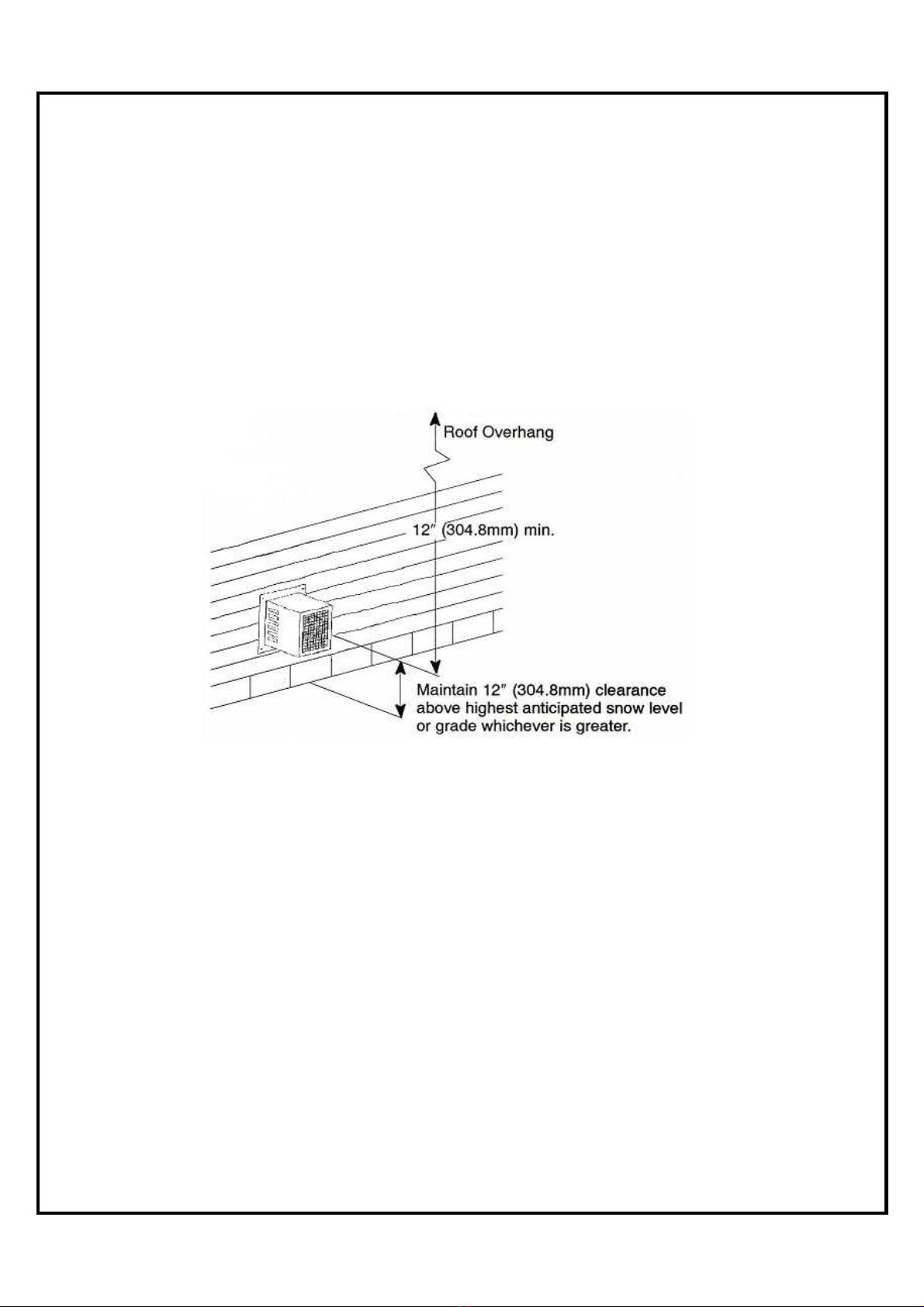
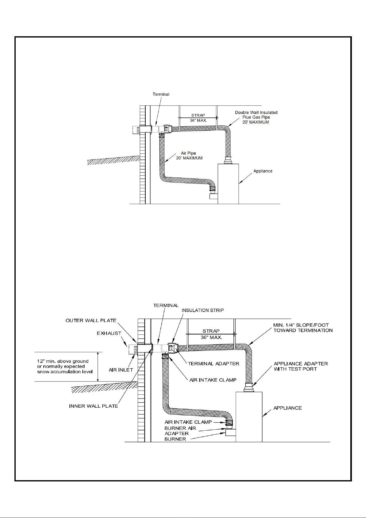
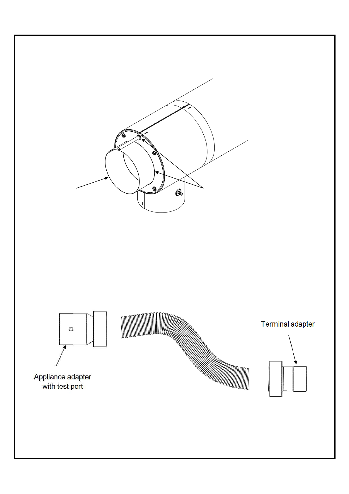
3.0 INSTALLATION REQUIREMENTS
The vent and combustion air intake must be installed in accordance to CSA B139/NFPA31 or
the appliance local codes. We do not recommend enclosing flexible vent pipe, nor having the
flexible vent pipe pass through interior walls, floors or ceilings. If the pipe passes through
walls, floors or ceilings the methods detailed in CSA B139/NFPA31 must be followed.