WARNING
This control system must be installed exactly as outlined in these instructions. Read all instructions completely before attempting
installation. Follow instructions carefully during installation. Any modications of this control or any of its components will void the
warranty and may pose a re hazard.
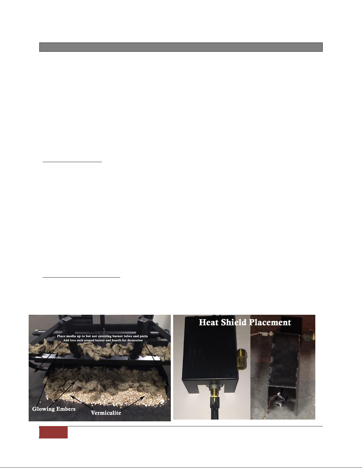
These instructions must be used as a supplement to the instructions supplied with the gas log set. Follow the gas log instructions
supplied by the manufacturers on the placement of the burner pan, log basket grate, burner media (sand or vermiculite), ember
material and the log placement. Please follow these instructions on the connection of the inlet line to the gas valve and then to the
burner pan assembly.
If your replace installation has glass doors, only operate the replace with glass doors in the fully open position.
INSTALLATION: VALVE KIT WITH PRE-EXISTING LOG SET
Make sure all gas ow is completely turned off to the gas log set. Make sure you have a certied and approved shut-off within 1.
6-feet of the replace, or whatever the local inspection authority requires.
Remove all logs and basket grate and set aside.2.
Disconnect the 3/8” Flared tting at the existing manual valve from the inlet gas supply.3.
Remove existing manual valve and ttings on the burner pan.4.
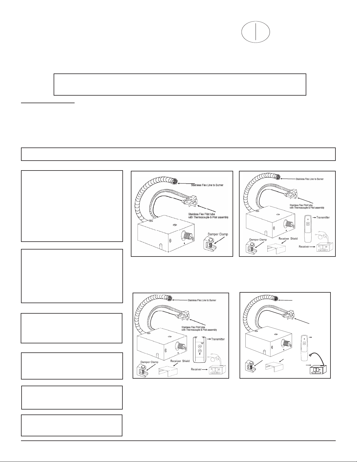
Locate a position on the back of the burner pan about 4-inches from the right or left side of the burner pan. (Figure #1 & #2)5.
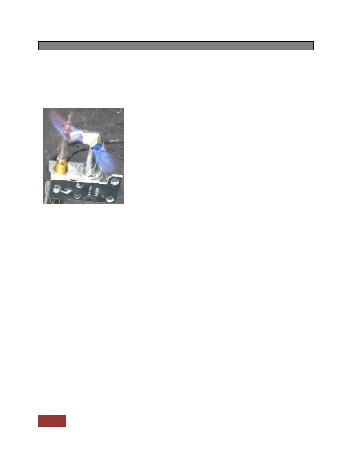
Mount pilot assembly to burner pan as shown in Figure # 3. Note this pilot bracket clips on the burner pan and holds the pilot at6.
a 45-degree position onto the pan with no screws required. A screw can be added to secure the pilot assembly if needed. Bend
1/4” stainless pilot tubing from pilot assembly until the bottom of the pilot bracket is resting against the pan. (This will hold the pilot
at the 45 degree position) then connect pilot tting to valve. (Use caution when bending pilot tubing not to kink the tubing or
locate the tubing in or over the burner pan).
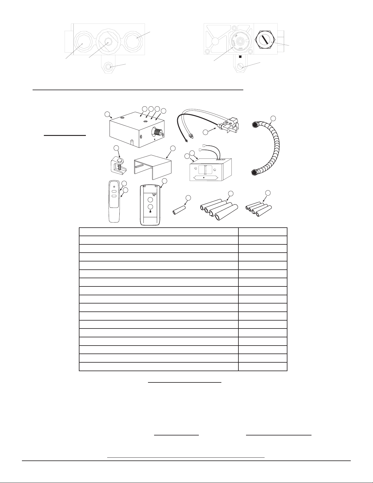
Locate the valve kit in the right or left front corner of the rebox as far forward as possible (See Figure #4).7.
Bend inlet gas supply line and connect the 3/8” are tting to gas valve 3/8” inlet connector (Fitting with printed label) (Use caution 8.
not to kink the line when bending).
Bend 12” stainless ex line and connect to valve outlet then connect other end to 3/8” are tting on burner pan 9. (Caution do not
let gas inlet line to the valve kit or gas outlet line from the valve kit be placed in or over the burner pan).
Turn on gas supply and check all connections for leaks using soapy water solution.10.
Follow valve pilot lighting instructions. After pilot is lit, check pilot ttings for leaks.11.
Reinstall basket grate and logs.12.
Install Damper stop (supplied with this valve kit) (This allows damper to remain slightly open to allow the pilot to vent)13.
NOTE: On all PROPANE installations it is recommended that an inlet pressure regulator be used.
INSTALLATION: VALVE KIT WITH NEW LOG SET
Make sure all gas ow is completely turned off to the replace. Make sure you have a certied and approved shut-off within 6-feet 1.
of the replace, or what ever the local inspection authority requires.
Follow the instructions supplied with the log set to locate the burner pan. Using the ttings, orice and gas supply line that came 2.
with the log set, connect the line to the inlet gas supply.
Locate a position on the back of the burner pan about 4-inches from the right or left side of the burner pan. Note: (Figure #1 & #2)3.
Mount pilot assembly to burner pan as shown in (Figure #3). Note this pilot bracket clips on the burner pan and holds the pilot at a4.
45-degree position onto the pan and no screws required. Note: A screw can be added to secure the pilot assembly if needed. Bend
1/4” stainless pilot tubing from pilot assembly until the bottom of the pilot bracket is resting against the pan. (This will hold the pilot
at the 45 degree position) then connect pilot tting to valve. (Use caution when bending pilot tubing not to kink the tubing or
locate the tubing in or over the burner pan)
Locate the valve kit in the right or left front corner of the rebox as far forward as possible (See Figure #4)5.
Bend inlet gas supply line and connect the 3/8” are tting to gas valve 3/8” inlet connector 6. (Fitting with printed label) (Use cau-
tion not to kink the line when bending).
Bend 12” stainless ex line and connect to valve outlet then connect other end to 3/8” are tting on burner pan (Caution do not let 7.
gas inlet line to the valve kit or gas outlet line from the valve kit be placed in or over the burner pan).
Turn on gas supply and check all connections for leaks using soapy water solution.8.
Follow valve pilot lighting instructions. After pilot is lit check pilot ttings for leaks.9.
Follow the instructions supplied with the log set to install ember material, basket grate and logs.10.
Install Damper stop (supplied with this valve kit) (This allows damper to remain slightly open to allow the pilot to vent).11.
NOTE: On all PROPANE installations it is recommended that an inlet pressure regulator be used.
REV 1-31-12 Page 2
American Flame AF-LMF Valve Kits