Force America SSC6100 CAN ULTRA Use and care manual

SSC6100 CAN ULTRA
Spreader Control
Calibration Manual
Firmware Version
1.11.1035

2

SSC6100 CAN Ultra Calibration Manual
Table of Contents
i
Table of Contents
Table of Contents.............................................................................................i
First Use Guide................................................................................................1
Hardware..........................................................................................................2
Operator Interface (PN: 1104696)........................................................................................ 2
Event Logging .................................................................................................3
Troubleshooting Event Logging ......................................................................................... 3
Calibration Menu.............................................................................................4
Entering the Calibration Menu............................................................................................. 4
The Calibration Menu ........................................................................................................... 5
Calibration Menu Navigation ............................................................................................... 6
Descriptions of Calibration Values................................................................9
Configuration ........................................................................................................................ 9
Ground Speed ..................................................................................................................... 11
Granular Materials .............................................................................................................. 12
Prewet Materials.................................................................................................................. 14
Direct Materials ................................................................................................................... 15
Truck .................................................................................................................................... 17
Tow Plow.............................................................................................................................. 27
Inputs ................................................................................................................................... 32
Outputs ................................................................................................................................ 34
Event Logging..................................................................................................................... 36
Alarms.................................................................................................................................. 40
Systems Management........................................................................................................ 43
AutoCalibration .............................................................................................50
AutoCalibration of Axle Pulses ......................................................................................... 50
Troubleshooting AutoCalibration of Axle Pulses............................................................ 52
AutoCalibration of Granular Material Displacement ....................................................... 53
Troubleshooting AutoCalibration of Granular Material Displacement.......................... 54
AutoCalibration of Prewet Material Displacement .......................................................... 55
Troubleshooting AutoCalibration of Prewet Material Displacement............................. 56
AutoCalibration of Direct Liquid Material Displacement ................................................ 57
Troubleshooting AutoCalibration of Direct Liquid Material Displacement................... 58
AutoCalibration of Tow Plow Granular Material Displacement...................................... 59
Troubleshooting AutoCalibration of Tow Plow Granular Material Displacement........ 60
AutoCalibration of Tow Plow Prewet Material Displacement......................................... 61
Troubleshooting AutoCalibration of Tow Plow Prewet Material Displacement ........... 62

SSC6100 CAN Ultra Calibration Manual
Table of Contents
ii
AutoCalibration of Tow Plow Direct Liquid Material Displacement .............................. 63
Troubleshooting AutoCalibration of Tow Plow Direct Liquid Material Displacement. 64
Driver Key Creation.......................................................................................65
Joystick Normalization .................................................................................66
Appendix A –Default Settings and Import/Export Types..........................67
Appendix B –Sample Exported Calibration Text File................................75
SSC6100 CAN Ultra Calibration Manual
First Use Guide
1
First Use Guide
The first time you configure your SSC6100, you will need to complete the following steps to
ensure that your vehicle runs at optimum efficiency:
Step:
Page Number:
1. Configure your system-wide options.
9
2. Calibrate your ground speed sensor.
11
3. Calibrate your auger minimum and maximum
settings.
18
4. Calibrate your auger maximum RPM.
18
5. Define your granular material settings.
12 & 20
6. Calibrate each granular material’s displacement
rates.
21
If you use prewet systems, also complete the following steps:
Step:
Page Number:
7. Calibrate your prewet minimum and maximum
settings, if necessary.
24
8. Calibrate your prewet maximum RPM, if necessary.
24
9. Define your prewet material settings.
14 & 25
10. Calibrate each prewet material’s displacement rates.
25
If you use direct systems, also complete the following steps:
Step:
Page Number:
11. Calibrate your direct minimum and maximum
settings, if necessary.
26
12. Calibrate your direct maximum RPM, if necessary.
26
13. Define your direct material settings.
15 & 26
14. Calibrate each direct material’s displacement rates.
26
If you use event logging, also complete the following steps:
Step:
Page Number:
15. Follow the steps outlined in the Event Logging
section, depending on whether you use PreCise
MRM or AVL event logging.
3
It is recommended that you export all your
settings to a USB flash drive after configuring
them. They can then be imported into other
vehicles to save time. See page 43.
SSC6100 CAN Ultra Calibration Manual
Hardware
2
Hardware
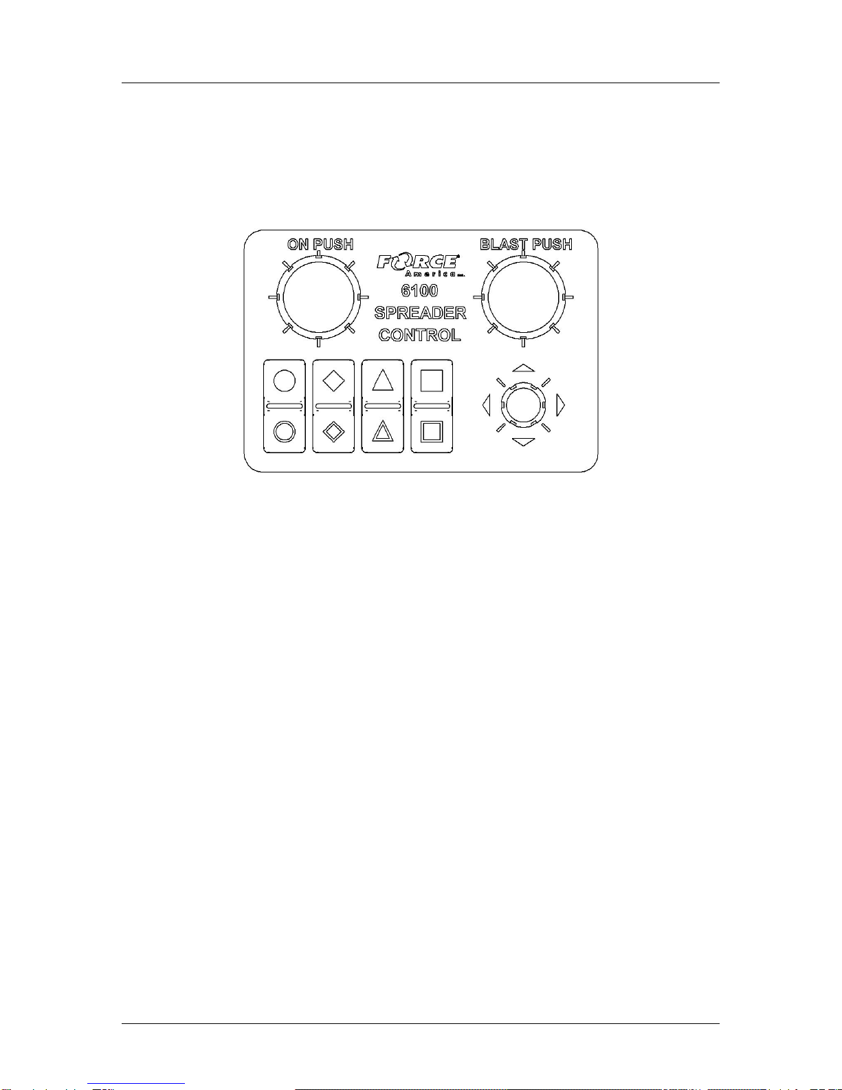
Operator Interface (PN: 1104696)
The Operator Interface lets you enter the Calibration Menu, select and edit settings, and run
outputs.
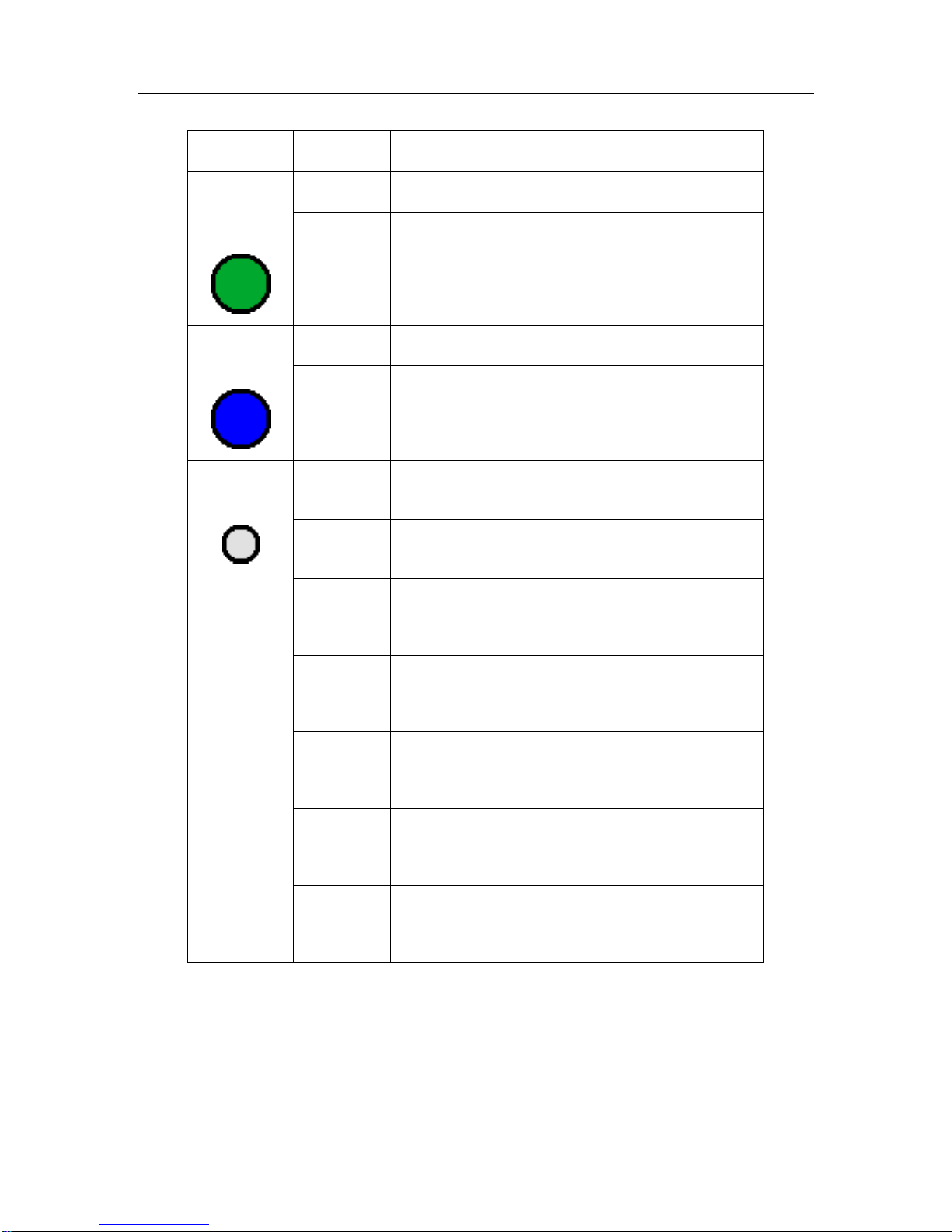
Figure 1: 1104696 Operator Interface
The Operator Interface has a single-axis, green On/Standby encoder, a single-axis, blue Blast
encoder, a triple-axis gray Navigation Joystick (Nav Stick), and eight “soft switches” that act as
pushbuttons for SSC6100 functions. The functions of all these encoders and buttons change
depending on portion of the SSC6100 system that is active.
You will use the Operator Interface to navigate the Calibration Menu. For more information on
which encoders and buttons perform which functions, see Calibration Menu Navigation on page
6.

SSC6100 CAN Ultra Calibration Manual
Event Logging
3
Event Logging
Event Logging is a method of vehicle usage monitoring that sends spreader data from the 6100
spreader control to an external device for processing.
To use Event Logging with a PreCise™ MRM device:
1. Contact your local FORCE America Representative to purchase PreCise MRM devices
that fit your needs.
2. Connect one PreCise MRM device to each vehicle you wish to equip with Event Logging.
The PreCise MRM devices connect to a DB-9 connector on the included RS-232 Serial
Harness.
3. Enter the 6100’s Calibration Menu.
4. Set the Configuration → Enabled Options → Event Logging menu item to PreCise MRM.
5. Configure your Event Logging settings in the Configuration →Event Logging menu. See
page 36 for more detailed information.
6. Exit the Calibration Menu.
Upon leaving Calibration, the 6100 will authenticate with the PreCise MRM device. Once
a successful connection has been established, the 6100 shall begin sending event data
to the PreCise MRM device.
To use Event Logging with an AVL device other than PreCise™ MRM:
1. Work with your preferred AVL developer and your local FORCE America Representative
to purchase an Event Logging Authentication Module for each vehicle you wish to equip
with Event Logging.
2. Connect an Event Logging Authentication Module to each vehicle you wish to equip with
Event Logging. These connect to a two-pin connector attached to the External 12-pin
Harness (P/N 1016023).
3. Connect one AVL device (provided by the AVL developer) to each vehicle you wish to
equip with Event Logging. The AVL device connects to a DB-9 connector on the included
RS-232 Serial Harness.
4. Enter the 6100’s Calibration Menu.
5. Set the Configuration → Enabled Options → Event Logging menu item to AVL.
6. Exit the Calibration Menu.
Upon leaving Calibration, the 6100 will authenticate with the Event Logging
Authentication Module and the AVL Device. Once a successful connection has been
established, the 6100 shall begin sending event data to the AVL device.
Troubleshooting Event Logging
Please see the Troubleshooting & Error Conditions section in the 6100 CAN Ultra Operation
Manual, M0123.
SSC6100 CAN Ultra Calibration Manual
Calibration Menu
4
Calibration Menu
Entering the Calibration Menu
The Calibration Menu is entered using the Calibration Button on the Menu Soft Switch Pane on
the Operation Screen. In order to enter the Calibration Menu, the vehicle must be in Standby.
Unlike the Data Menu or the Unload Menu, the Calibration Menu requires the entry of an Access
before it will appear.
To enter Calibration:
1. Move the Operator Interface’s Gray Navigation Joystick, or Nav Stick left or right until the
MENU soft switch pane is displayed.
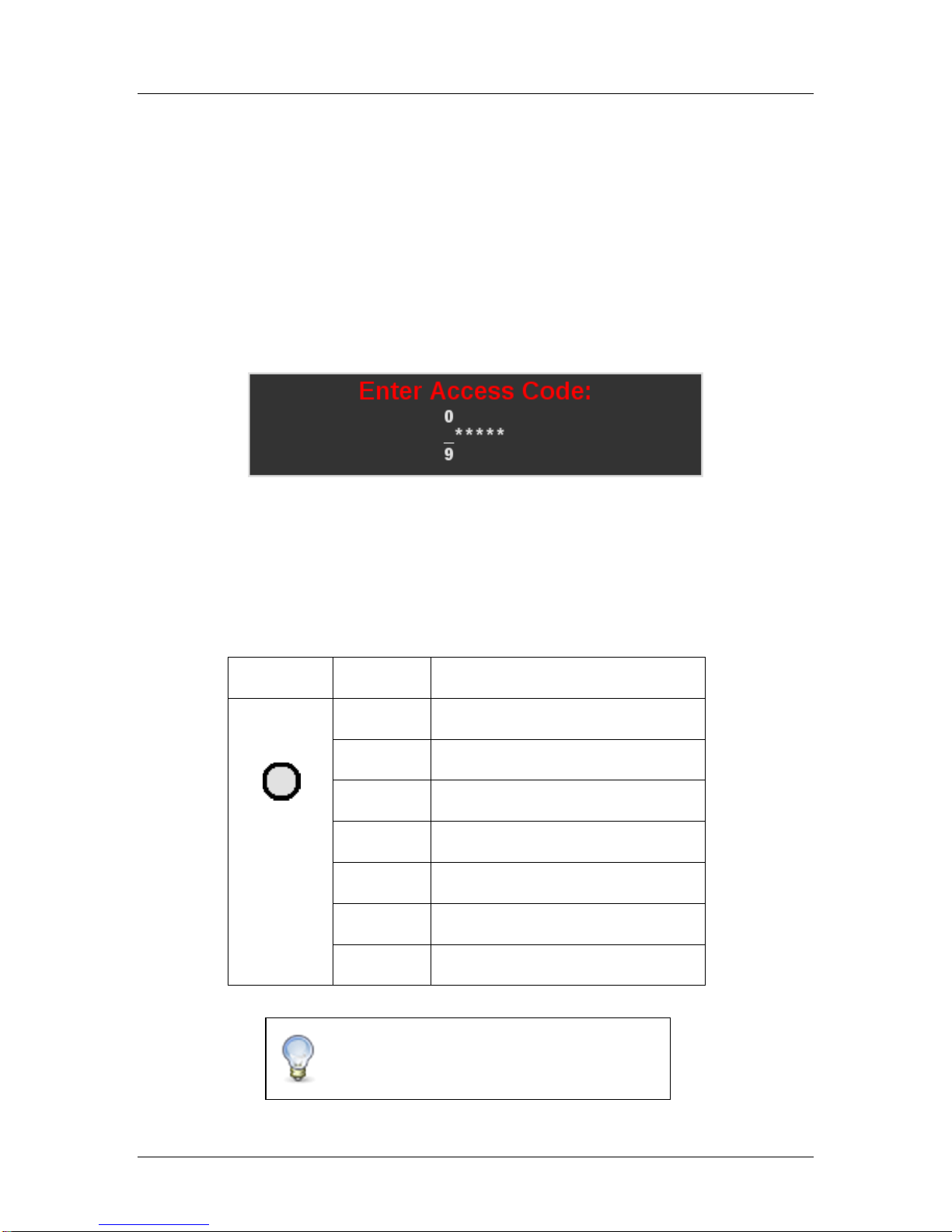
2. Press the CALIBRATION soft switch to open the Calibration Menu. The Access Code
window will appear, as shown in Figure 2.
Figure 2: Access Code Window
3. Enter the access code using one of the following three methods:
a. Connect the Supervisor USB Key.
b. Hold the Supervisor iButton to the iButton port on the Operator Interface.
c. Use the Nav Stick and the table below to enter the Access Code.
When entering the Access Code, the Nav Stick has the following functions:
Input
Action
Function
Gray Nav
Stick
Twist Left
Decrease highlighted digit by 1.
Twist Right
Increase highlighted digit by 1.
Up
Increase highlighted digit by 1.
Down
Decrease highlighted digit by 1.
Left
Highlight previous digit.
Right
Highlight next digit.
Pushbutton
Enter Access Code.
The default access code is 000000. For
information on changing the Access Code,
see page 9.
SSC6100 CAN Ultra Calibration Manual
Calibration Menu
5
The Calibration Menu
The Calibration Menu contains all of the settings required to operate an SSC6100 system.
Settings within the Calibration Menu are broken up into two categories: Fleet-Wide Settings and
Vehicle Specific Settings.
Fleet-Wide Settings
Fleet-Wide Settings are likely to be set the same across an entire fleet of vehicles. These
include things such as the supervisor’s access code, the measurement units, granular
and prewet loop modes, and material set rates.
Vehicle Specific Settings
Vehicle Specific Settings are likely to vary between each vehicle. These include hardware
related settings, such as axle pulses, minimum and maximum currents, and displacement
values which may change due to manufacturing or installation differences.
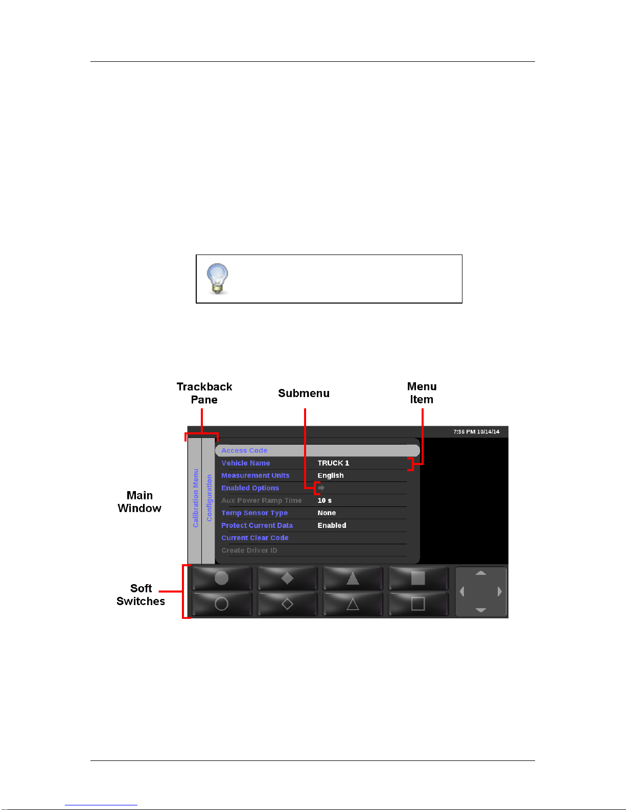
The Calibration Menu uses a “NeverLost” menu system to ensure that navigating the settings is
easy and quick. The Calibration Menu has four subsections: the Trackback Pane, Submenus,
Menu Items, and the Soft Switches, as shown in Figure 3.
Figure 3: Calibration Menu
The Trackback Pane
The Trackback Pane records your current location within the Calibration Menu. It will always list
the submenus you traveled through to see your current screen. The submenu you are currently
viewing will always be the furthest right in the Trackback Pane. For example, in Figure 3, the user
has entered the Calibration Menu and is viewing the Configuration submenu.
For a complete list of Fleet-Wide and Vehicle
Specific Settings, see Appendix A –Default
Settings and Import/Export Types on page 67.

SSC6100 CAN Ultra Calibration Manual
Calibration Menu
6
Submenus
Submenus are not calibration settings, but instead are containers for other calibration settings.
For example, all system-wide calibration settings are contained under the Configuration
submenu.
A calibration item is a submenu if it displays an arrow instead of a calibration value. Also,
submenus will show a preview pane when they are highlighted, while normal calibration items will
not. The preview pane shows all of the calibration items available within the submenu.
If a submenu has gray text instead of blue, none of the calibration options within the submenu will
be able to be change because another calibration item has disabled it. For example, the Direct
Liquid submenu will be gray if Calibration → Enabled Options → Direct is disabled.
Calibration Items
Calibration items are changeable settings. They have a name and display a value in the menu.
If a Calibration item has gray text instead of blue, it is unable to be changed because another
calibration item has disabled it. For example, the Calibration → Enabled Options → Simultaneous
Gran/Dir calibration item will be gray if Calibration → Enabled Options → Direct is disabled.
The Soft Switches
The Soft Switches are located on the bottom left of the 6100’s display and are used to instantly
activate or deactivate menu functions. These 8 soft switches directly correspond to the labeled
buttons on the Operator Interface. For example, pressing the Filled Circle button on the Operator
Interface will activate the function shown on the Filled Circle soft switch.
Within the Calibration Menu, the Soft Switches no longer correspond to the functions available in
the Soft Switch Panes on the Operator Screen (see the 6100 Operation Manual, M0123). Instead,
they run their own custom functions depending on your location within the Calibration Menu.
Calibration Menu Navigation
All actions within the Calibration Menu are done using the Operator Interface. Most actions are
completed with the gray Nav Stick, but the green On/Standby and blue Blast encoders do
occasionally run functions.
All actions on the 6100 are activated using the Operator Interface. The table below describes
each button and its actions while in the Calibration Menu. Not all actions are available at all
locations within the menu.
SSC6100 CAN Ultra Calibration Manual
Calibration Menu
7
Input
Action
Function
Green
On/Standby
Encoder
Twist Left
Decrease the auger set rate.
Twist Right
Increase the auger set rate.
Pushbutton
Run outputs.
Stop outputs.
Blue Blast
Encoder
Twist Left
Decrease the spinner set rate.
Twist Right
Increase the spinner set rate.
Pushbutton
None.
Gray Nav
Stick
Twist Left
Decrease digit by 1.
Select previous calibration value.
Twist Right
Increase digit by 1.
Select next calibration value.
Up
Highlight previous menu item.
Increase digit by 1.
Select previous calibration value.
Down
Highlight next menu item.
Decrease digit by 1.
Select next calibration value.
Left
Return to previous submenu.
Select previous digit.
Exit Calibration Menu.
Right
Enter Submenu.
Edit Calibration Item.
Select next digit.
Pushbutton
Enter Submenu.
Edit Calibration Item.
Save Calibration Item.
To highlight a different calibration item or submenu:
1. Move the Nav Stick up or down until the menu item you want is highlighted.
To edit a calibration item or enter a submenu:
1. Highlight the calibration item you wish to change.
2. Press the Nav Stick’s pushbutton.

SSC6100 CAN Ultra Calibration Manual
Calibration Menu
8
To save a calibration item being edited:
1. Press the Nav Stick’s pushbutton. You will be returned to the submenu containing the
calibration item.
To exit the Calibration Menu:
1. Move the Nav Stick left until you reach the main Calibration Menu screen.
2. Move the Nav Stick left one more time. You will be returned to the Operation Screen.

SSC6100 CAN Ultra Calibration Manual
Descriptions of Calibration Values
9
Descriptions of Calibration Values
This section will describe each calibration value in the Calibration Menu in detail. For a complete
list of default settings, see Appendix A –Default Settings and Import/Export Types on page 67.
Configuration
The Configuration menu allows you to configure vehicle-wide settings, such as the supervisor
access and clear codes, the vehicle's name, and enabled options.
Access Code
The Access Code menu item changes the supervisor code required to enter the
Calibration Menu or clear season data totals. It consists of 6 numbers and/or underscores
which are set individually. The default value is 000000.
Vehicle Name
The Vehicle Name menu item changes the descriptive name given to the vehicle. This
name is displayed on reports and as part of filenames when exporting. It can be set to 10
alphanumeric characters. The default value is TRUCK1.
Measurement Units
The Measurement Units menu item changes the type of measurement system the vehicle
uses for inputs and outputs. The available options are English and Metric. The default
value is English.
When switching from English to Metric or vice-versa, all configuration items that use the
previous measurement units will be converted to the new units.
Enabled Options
The Enabled Options submenu lists all of the system-wide settings that can be enabled
or disabled.
Mixed Material
The Mixed Material menu item enables mixed material application for the entire
system. This should only be used with a Highway Equipment Xzalt™ system.
The default value is disabled.
For more information on Mixed Material, see the SSC6100 CAN Ultra with
Xzalt™ Operation Manual (M0109) and the SSC6100 CAN Ultra with Xzalt™
Calibration Manual (M0110). These manuals will be included with your Xzalt™
system.
When Mixed Material is enabled the connection and operation of the module and
mode will be determined by selecting it as a truck implement.
Sim Speed
The SimSpeed menu item enables or disables SimSpeed operation. Enabling
SimSpeed will show the SimSpeed data item and the SimSpeed soft switches in
the UTIL soft switch pane. The default value is disabled.
Distance Measure
The Distance Measure menu item enables or disables distance measurement
operation. Enabling Distance Measure will show the DISTANCE data item in the
top data item slot. It will also show the MEASURE DISTANCE and RESET
DISTANCE soft switches in the UTIL soft switch pane. The default value for the
Distance Measure menu item is disabled.

SSC6100 CAN Ultra Calibration Manual
Descriptions of Calibration Values
10
When SimSpeed is active, the SSC6100 will lock the MEASURE DISTANCE and
RESET DISTANCE soft switches. It will also put the SIMSPD data item in place
of the DISTANCE data item for as long as SimSpeed is enabled in Calibration.
Aux Power
The Aux Power menu item enables or disables the use of the auger valve to run
auxiliary functions. The default value is disabled. In order to operate the Aux
Power feature the base truck or attached truck implement needs to contain a
granular output.
Event Logging
The Event Logging menu item selects the kind of event logging that will be used
with the system. The options are Disabled, PreCise® MRM and AVL. The default
value is Disabled.
For more information on Event Logging, see Event Logging on page 3.
Driver ID
The Driver ID menu item enables or disables the driver login. Enabling Driver ID
will require the driver to log in using their Driver ID Key before running spreader
outputs. The default value is disabled.
Temperature Sensor
The Temperature Sensor menu item selects the kind of temperature sensor
attached to the 6100. The options are None, PreCise® MRM, RoadWatch, and
Vaisala. The default value is None.
Temp Comp
The Temp Comp menu item enables or disables temperature compensation. The
default value is Disabled.
Aux Power Ramp Time
The Aux Power Ramp Time setting will affect how quickly or slowly the Aux Power output
will scale from minimum duty cycle to maximum duty cycle. Setting a longer ramp time
will cause the output to increase at a slower rate. This may be useful if the auxiliary
function’s motor is smaller than the auger motor. The default value is 10 seconds. The
range is 0 seconds to 10 seconds.
T-Comp Averaging
The T-Comp Averaging setting will affect how quickly or slowly the system adjusts the
application rate based on the road temperature readings by adjusting the number of
samples that are used to determine the compensation percentage. Selecting a low value
for this setting will allow the system to react quickly to changes detected in the road
temperature. Larger values will allow the system to respond slower to temperature
changes and not adjust the application rate as often. This setting will be influenced by
the rate at which the temperature sensor updates the controller with new readings. The
default value is 1 sample. The range is 1 to 1200 samples.
Protect Current Data
The Protect Current Data menu item enables or disables a password screen when
clearing “Current Data” from the Data menu. The clear code for current data is not the
same code as the supervisor access code required to enter the Calibration Menu or clear
season data. The default value is Enabled.

SSC6100 CAN Ultra Calibration Manual
Descriptions of Calibration Values
11
Current Clear Code
The Clear Current Code menu item changes the code required to clear the current data
from the Data menu. This code is not the same code as the supervisor access code
required to enter the Calibration Menu or clear season data totals. If Protect Current Data
is Disabled, this code does nothing. The default value is 314159.
Create Driver ID
The Create Driver ID menu item opens the Driver Key Wizard which is used to create
Driver ID Keys. See Driver Key Creation on page 65 for more information. If Driver ID is
Disabled this menu item does nothing.
Ground Speed
The Ground Speed menu allows you to configure settings for the vehicle's speedometer input.
Speedometer Type
The Speedometer Type setting selects the type of speedometer the SSC6100 Core
Module is connected to, either Electronic or Mechanical. Selecting one or the other
determines which kind of speedometer counts the core will listen for. The default value is
Electronic.
Pickup Sensitivity
The Pickup Sensitivity menu item changes the hardware sensitivity to the speedometer
signal. The available options are High, Low, and Custom. The default value is High.
Low Trip Point
The Low Trip Point sets the voltage that the speedometer signal must drop below in order
to cause a pulse. This value will only be editable when the Pickup Sensitivity is set to
Custom. The default value is 0.5 V.
The Low Trip Point should be set when the vehicle is moving. Have a passenger slowly
increase the low trip point until the menu item shows a mph/kph value greater than 0.
High Trip Point
The High Trip Point sets the voltage that the speedometer signal must climb above in
order to cause a pulse. This value will only be editable when the Pickup Sensitivity is set
to Custom. The default value is 2.0 V.
The High Trip Point should be set when the vehicle is moving. Have a passenger slowly
decrease the high trip point until the menu item shows a mph/kph value greater than 0.
Axle Pulses
The Axle Pulses menu item defines how many pulses from the speedometer input are
expected in 1 mile. Axle Pulses are used in all closed and open loop operating modes,
and should be configured as accurately as possible. The default value is 40000 pulses
per mile or 24855 pulses per kilometer.
The Axle Pulses should be set when the vehicle is moving. Have a passenger adjust the
Axle Pulses up or down until the speed displayed on the screen matches the vehicle’s
speedometer.
Jump Start Speed
The Jump Start Speed menu item sets a speed that the spreader will run at until that
speed is surpassed. For example, if Jump Start Speed is set to 15 mph, the spreader will
run as if ground speed was at 15 mph until the actual vehicle speed is above 15 mph.
The default value is 15 mph or 24 kph.

SSC6100 CAN Ultra Calibration Manual
Descriptions of Calibration Values
12
Overspeed Alarm
The overspeed alarm alerts the driver that he is exceeding the maximum allowed speed.
The options are Disabled, Spreading, and Always. The default value is Disabled. The
value of Spreading means that the alarm will only occur when the vehicle is spreading
and the Overspeed Speed is exceeded. The value of Always means that the alarm will
occur anytime the Overspeed Speed is exceeded.
Overspeed Speed
The Overspeed Speed menu item sets the speed that the vehicle must exceed for the
system to display the Overspeed Warning, if enabled. The default value is 45 mph or 72
kph.
Granular Materials
The Granular Materials menu allows you to configure settings that are used for general granular
material application and for the individual granular materials. These settings include custom
displacement, set, and blast rates for each material.
Enabled Options
The Enabled Options submenu lists all of the general granular application settings that
can apply to the truck and tow plow application systems.
Manual Mode
The Manual Mode menu item enables manual mode for all granular materials
and the Manual soft switch on the Operation Screens. The default value is
enabled.
Unload Mode
The Unload Mode menu item enables unload mode for all granular materials in
the Unload menu. The default value is disabled.
Blast Mode
The Blast Mode menu item sets Blast to either Time or Distance. When Blast is
activated, it will either run for a set amount of time or distance. The default value
is Time.
Blast Time
The Blast Time menu item sets the amount of seconds blast will run when it is
activated in Blast Time mode. The default value is 10 seconds.
Blast Distance
The Blast Distance menu item sets the amount of distance blast will run when it
is activated in Blast Distance mode. The default value is 250 feet.
Skip Mode
The Skip Mode setting enables or disables the Skip Mode soft switch on the
GRAN pane, which activates skipping for granular materials. The default value is
disabled.
After enabling Skip Mode, set the Skip On Distance and Skip Off Distance menu
items appropriately.
Skip On Distance
The Skip On Distance menu item sets the amount of distance the auger /
conveyor and spinner will operate normally when Skip Mode is active. The
default value is 250 feet or 16 meters.

SSC6100 CAN Ultra Calibration Manual
Descriptions of Calibration Values
13
Skip Off Distance
The Skip Off Distance menu item sets the amount of distance the auger /
conveyor and spinner will stop or “skip” when Skip Mode is active. The default
value is 250 feet or 16 meters.
Loop Mode
The Loop Mode menu item sets the granular output into either Closed Loop or Open
Loop Mode. The default is Closed Loop Mode.
Materials Enabled
The Materials Enabled menu item changes how many granular materials will be available
to the 6100 during operation, ranging from 1 to 10. If a granular material is configured
with non-default settings and then is disabled with this menu item, its custom settings will
not be cleared. The default value is 1.
Material 1, Material 2, Material 3, etc.
Entering the Material # submenu presents the custom settings available for a particular
granular material.
Material Name
The Material Name menu item allows you to set a custom name for the granular
material, such as “SAND” or “SALT”. A maximum of 5 characters can be used in
the material name. This name will appear on the Operation Screen when
selected, as well as in all Data Reports. The default value is MAT1, MAT2,
MAT3, etc.
# of Set Rates
The # of Set Rates menu item changes how many set rates will be available to
the driver during operation, ranging from 1 to 10. The default value is 10. If a set
rate is configured with non-default settings and then is disabled with this menu
item, its custom settings will not be cleared.
Set Rates
Entering the Set Rate submenu presents a list of all the custom set rates
available for the granular material.
Set Rate 1, Set Rate 2, Set Rate 3, etc.
The Set Rate menu item configures which pounds per mile or kilograms
per kilometer setting will be output when the user chooses the
corresponding set rate.
A Granular Material Set Rate has a range of 0 to 9999 pounds per mile,
or 0 to 9999 kilograms per kilometer. The default value is 100, 200, 300,
400, etc. pounds per mile or kilograms per kilometer.
Set Rate 1 will always be used during operation when the green
On/Standby Encoder is turned counter-clockwise more than 10 clicks.
Turning the green On/Standby Encoder clockwise from Set Rate 1 will
switch to the next Set Rate at 1 rate per click. Set Rate 2 will always be 1
click before Set Rate 3, and so on.
Blast Rate
The Blast Rate menu item sets the amount of granular material the spreader will
spread when it is in Blast mode. The default value is 1000 pounds per mile or
750 kilograms per kilometer.

SSC6100 CAN Ultra Calibration Manual
Descriptions of Calibration Values
14
Temperature Profile 1, Temperature Profile 2, Temperature Profile 3, etc.
Entering the Temperature Profile # submenu presents the custom settings available for a
particular temperature profilel.
Compensation at X, Compensation at Y, Compensation at Z, etc.
The Compensation at # menu item configures the temperature compensation
adjustment for the given temperature. The Compensation will run the granular
material at the given percent of its normal set rate at the listed temperature. A
Compensation Rate has a range of 0 to 500%. The default value is 100%.
Prewet Materials
The Prewet Materials menu allows you to configure settings that are used for general prewet
material application and for the individual prewet materials. These settings include custom
displacement, set, and blast rates for each material.
Enabled Options
The Enabled Options submenu lists all of the general prewet application settings that can
apply to the truck and tow plow application systems.
Manual Mode
The Manual Mode menu item enables manual mode for all prewet materials and
the Prewet Manual soft switch on the Operation Screen. The default value is
disabled.
Unload Mode
The Unload Mode menu item enables unload mode for all prewet materials in the
Unload menu. The default value is disabled.
Loop Mode
The Loop Mode menu item sets the prewet output into Closed Loop, Open Loop, or
Manual Mode. The default is Closed Loop Mode.
Materials Enabled
The Materials Enabled menu item changes how many prewet materials will be available
to the 6100 during operation, ranging from 1 to 10. The default value is 1. If a prewet
material is configured with non-default settings and then is disabled with this menu item,
its custom settings will not be cleared.
Material 1, Material 2, Material 3, etc.
Entering the Material # submenu presents the custom settings available for a particular
prewet material.
Material Name
The Material Name menu item allows you to set a custom name for the prewet
material, such as “PWT1” or “CACL”. A maximum of 5 characters can be used in
the material name. This name will appear on the Operation Screen when
selected, as well as in all Data Reports. The default value is PWT1, PWT2,
PWT3, etc.
# of Set Rates
The # of Set Rates menu item changes how many set rates will be available to
the driver during operation, ranging from 1 to 10. If a set rate is configured with
non-default settings and then is disabled with this menu item, its custom settings
will not be cleared. The default value is 6.

SSC6100 CAN Ultra Calibration Manual
Descriptions of Calibration Values
15
Set Rates
Entering the Set Rate submenu presents a list of all the custom set rates
available for the prewet material.
Set Rate 1, Set Rate 2, Set Rate 3, etc.
The Set Rate menu item configures which gallons per ton or liters per ton
setting will be output when the user chooses the corresponding set rate.
A Prewet Material Set Rate has a range of 0.0 to 72.0 gallons per ton, or
0.0 to 72.0 liters per ton. The default value is 3.0, 4.0, 5.0, etc. gallons
per ton.
Set Rate 1 will always be used during operation when the gray Nav Stick
is turned counter-clockwise more than 10 clicks. Turning the gray Nav
Stick clockwise from Set Rate 1 will switch to the next Set Rate at 1 rate
per click. Set Rate 2 will always be 1 click before Set Rate 3, and so on.
Temperature Profile 1, Temperature Profile 2, Temperature Profile 3, etc.
Entering the Temperature Profile # submenu presents the custom settings available for a
particular temperature profilel.
Compensation at X, Compensation at Y, Compensation at Z, etc.
The Compensation at # menu item configures the temperature compensation
adjustment for the given temperature. The Compensation will run the prewet
liquid at the given percent of its normal set rate at the listed temperature. A
Compensation Rate has a range of 0 to 500%. The default value is 100%.
Direct Materials
The Direct Materials menu allows you to configure settings that are used for general direct liquid
application and for the individual direct liquid materials. These settings include custom
displacement, set, and blast rates for each material.
Enabled Options
The Enabled Options submenu lists all of the general direct liquid application settings that
can apply to the truck and tow plow application systems.
Manual Mode
The Manual Mode menu item enables manual mode for all direct materials and
the Direct Manual soft switch on the Direct Soft Switch Pane. The default value is
disabled.
Unload Mode
The Unload Mode menu item enables unload mode for all direct materials in the
Unload menu. The default value is disabled.
Blast Mode
The Blast Mode menu item sets Blast to either Time or Distance. When Blast is
activated, it will either run for a set amount of time or distance. The default value
is Time.
Blast Time
The Blast Time menu item sets the amount of seconds blast will run when it is
activated in Blast Time mode. The default value is 10 seconds.

SSC6100 CAN Ultra Calibration Manual
Descriptions of Calibration Values
16
If simultaneous application is active, Direct Liquid’s Blast Time will have no effect.
Instead, the Granular Blast Time will be used.
Blast Distance
The Blast Distance menu item sets the amount of distance blast will run when it
is activated in Blast Distance mode. The default value is 250 feet.
If simultaneous application is active, Direct Liquid’s Blast Distance will have no
effect. Instead, the Granular Blast Distance will be used.
Loop Mode
The Loop Mode menu item sets the direct liquid output into either Closed Loop or Open
Loop Mode. The default is Closed Loop Mode.
Materials Enabled
The Materials Enabled menu item changes how many direct liquid materials will be
available to the 6100 during operation, ranging from 1 to 10. The default value is 1. If a
direct liquid material is configured with non-default settings and then is disabled with this
menu item, its custom settings will not be cleared.
Material 1, Material 2, Material 3, etc.
Entering the Material # submenu presents the custom settings available for a particular
direct liquid material.
Material Name
The Material Name menu item allows you to set a custom name for the direct
liquid material, such as “DIR1” or “MGCL”. A maximum of 5 characters can be
used in the material name. This name will appear on the Operation Screen when
selected, as well as in all Data Reports. The default value is DIR1, DIR2, DIR3,
etc.
# of Set Rates
The # of Set Rates menu item changes how many set rates will be available to
the driver during operation, ranging from 1 to 10. If a set rate is configured with
non-default settings and then is disabled with this menu item, its custom settings
will not be cleared. The default value is 10.
Set Rates
Entering the Set Rate submenu presents a list of all the custom set rates
available for the direct liquid material.
Set Rate 1, Set Rate 2, Set Rate 3, etc.
The Set Rate menu item configures which gallons per mile or liters per
kilometer setting will be output when the user chooses the corresponding
set rate.
A Direct Liquid Material Set Rate has a range of 0.0 to 100 gallons per
mile, or 0.0 to 250 liters per kilometer. The default value is 20, 25, 30,
etc. gallons per mile or 50, 60, 70, etc. liters per kilometer.
Set Rate 1 will always be used during operation when the Direct Rate
Down soft switch is pressed more than 10 times. Pressing the Direct
Rate Up soft switch from Set Rate 1 will switch to the next Set Rate at 1
rate change per press. Set Rate 2 will always be 1 press before Set Rate
3, and so on.
Other manuals for SSC6100 CAN ULTRA
4
Table of contents
Other Force America Control Unit manuals

Popular Control Unit manuals by other brands

Burkert
Burkert 5281 operating instructions

Siemens
Siemens VGD4 series Operation Manual and Mounting Instructions

Ampetronic
Ampetronic HLS-DM2 Installation handbook

United Technologies
United Technologies Kidde FX-NAC Installation sheet

ETAS
ETAS PB1651PWM1 user guide

MX
MX Atmos Low Pressure Fitting instructions


