Grand Canyon Gas Logs 2BRN-18 Operating instructions

1
Grand Canyon Gas Logs---3435 E. Atlanta Ave---Phoenix, AZ 85040
INSTALLATION AND OPERATIONS GUIDE FOR
GRAND CANYON GAS LOG SYSTEMS
Grand Canyon Gas Logs, logs are made of cement refractory material re-enforced with steel fibers. Each of the logs are hand painted and
hand finished to recreate the most realistic logs available on the market. The gas burner system is designed to recreate and burn like a real
wood burning fireplace with a natural looking flame. With this in mind the gas log sets MUST be burned in a fully vented, non-combustible
fireplace with the DAMPER COMPLETELY OPEN and the chimney free of any obstruction or restrictions. The fireplace must be designed and
approved to bur wood.
The realistic flame produced by Grand Canyon Gas Log burners produce carbon monoxide and soot. Under standard conditions these
byproducts are exhausted up the chimney. IF the fumes or soot from the burning gas are evident in the room when the damper is fully open
it indicates that the fireplace draft is defective. IF this happens DO NOT operate your gas logs until the fireplace drat is corrected, call a
service technician to fix the problem.
Installation and service must be provided by a qualified installer, service agency or
gas supplier
WARNING: If the information in this
manual is not followed exactly, a fire or
explosion may result, causing property
damage, personal injury or loss of life
-Do not store or use gasoline or other
flammable vapors and liquids in the
vicinity of this or any application
WHAT TO DO IF YOU SMELL GAS
Do not try to light any appliance
Do not touch any electrical switch;
do not use any phone in the building
Immediately call the gas supplier
from a neighbor’s phone. Follow
the gas supplier’s instructions
If you cannot reach the gas supplier,
call the fire department.
-Installation and service must be
performed by a qualified installer,
service agency or the gas supplier
Grand Canyon Gas Log sets are to be installed only in a solid-
fuel burning fireplace with working flue and construction of
noncombustible material. The installation including
provisions for combustion and ventilation air must conform
with the National Fuel Gas Code, ANSI Z223.1/NFPA 54, or
the CSA B149.1 Natural Gas and Propane Installation Code,
and applicable local building codes.
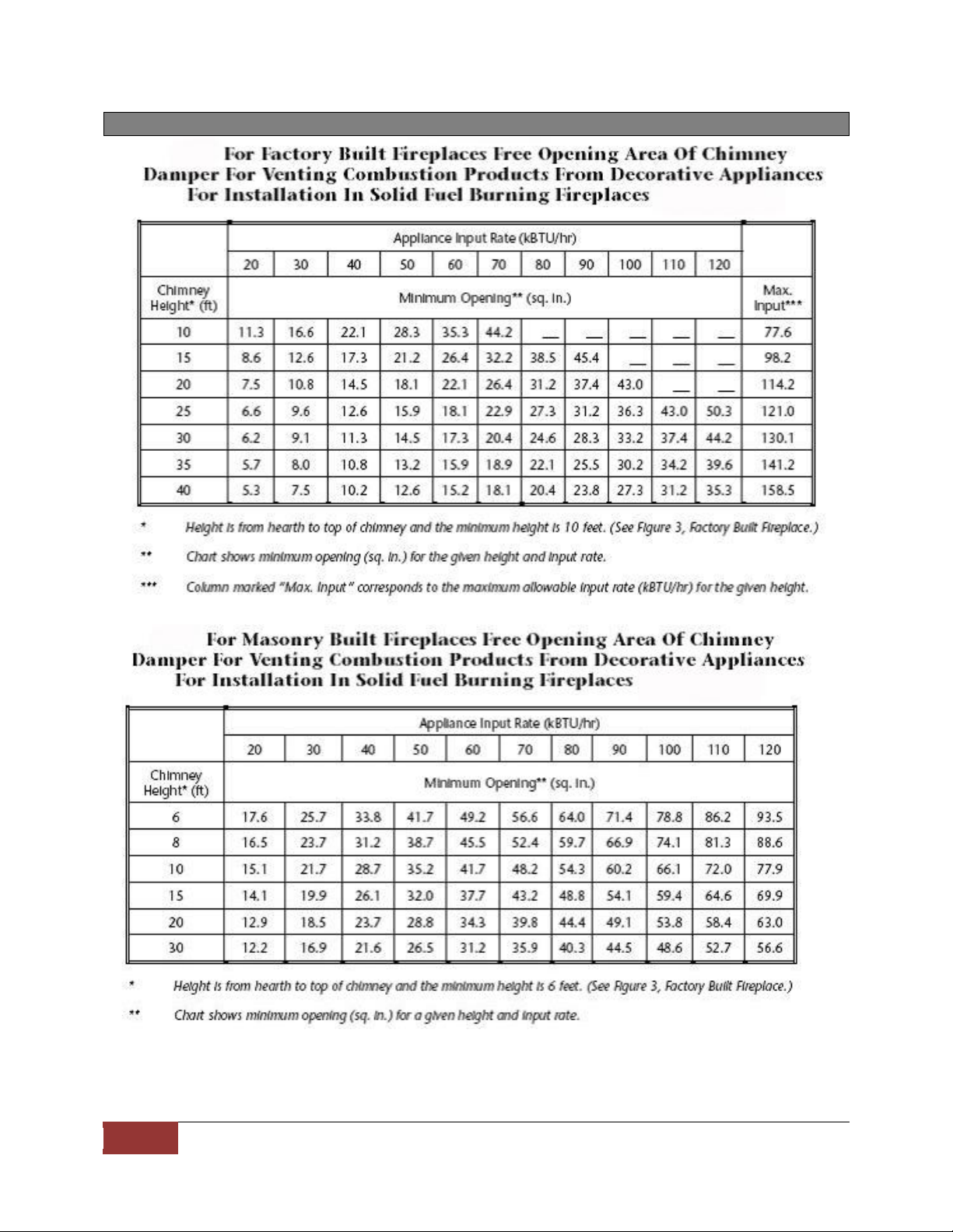
A damper clamp is included to maintain the minimum
permanent vent opening and to prevent full closure of the
damper blade. The chimney damper must be fully opened
when burning the log set. The log set is designed to burn
with a yellow flame, thus adequate ventilation is absolutely
necessary.
To comply with certifications, listings, and building code
acceptances, and for safe operation and proper
performance of this log set, use only Grand Canyon Gas Logs
parts and accessories. Use of other controls, parts, and
accessories that are not designed for use with Grand Canyon
Gas Logs log set is prohibited and will void all the
warranties, certifications, listings and building code
approvals, and may cause property damage, personal injury
or loss of life.
WARRANTY
Grand Canyon Gas Logs burners and logs carry a
lifetime warranty against breakage and defects to the
original purchaser. ALL GCGL valves, pilot assemblies
and electrical components carry a 2 year warranty as
long as installed indoors and installed by a licensed
professional. Further warranty information can be
found in the warranty section of this guide.
INSTALLER: Leave this manual with the log set
CONSUMER: Retain this manual for future reference.
Report # 535-L-01-5
Designed Certified to Vented
Decorative Appliance
ANSIZ21.60-2012/CSA2.26-2012
CGA 2.17-M91 (R209)
Gas-Fired Appliances for use at
High Altitudes
Burner Systems:
2BRN-18 3BRN-18
2BRN-24 3BRN-24
2BRN-30 3BRN-30
2BRN-36 3BRN-36
2BRN-42 3BRN-42
Manuel de langue française disponibles à
www.grandcanyongaslogs.com/manual/
Approved for high altitudes up to 4500ft
(1300m) in Canada

2
Grand Canyon Gas Logs---3435 E. Atlanta Ave---Phoenix, AZ 85040
IMPORTANT INFORMATION
WARNING: This appliance assembly contains burner orifices specifically for the input gas specified on the burner
and box, as well as the Btu rating specified in this manual. Modifying or failure to use the factory orifice may
cause property damage, personal injury or loss of life.
Read these instructions completely before installing and using Grand Canyon Gas Log system.
1. Gas type will be indicated on the burner and the box. Do not use a natural gas burner with propane or a
propane burner with natural gas.
2. The installation, provisions for combustion, and ventilation air must conform to the National Fuel Gas
Code, ANSI Z223.1/NFPA54, or the CSA B 149.1, National Gas and Propane Installation Code.
3. For warranty to be valid gas log sets must be installed by a NFI certified or other qualified professional
installer.
4. This appliance must be installed only in a solid-fuel burning fireplace with a working flue and constructed
of non-combustible materials. Solid fuels are not to be burned in a fireplace where a decorative appliance
has been installed.
5. A permanent free opening must be provided by either the fireplace chimney or chimney damper to vent
carbon monoxide and other flue gases. Any chimney damper must be fixed in a manner, which will
maintain the permanent free opening at all times. Use the table at the bottom of this page to determine
the minimum permanent free opening based on chimney height and the appliance Btu rating.
6. A fireplace screen must be in place when the appliance is operating and, unless other provisions for
combustion air are provided, the screen shall have an opening(s) for introduction of combustion air. With
use of glass doors, doors must be open while the appliance is burning to assure proper ventilation.
7. The minimum inlet supply pressure for the purpose of input adjustment is 5.0 inches (natural gas) 8.0
inches (propane) in water column. The maximum inlet supply pressure is 10.5 inches (natural gas) 13.0
inches (propane) in water column.
8. The appliance and its individual shut-off valve must be disconnected from the gas supply piping system
during any pressure testing of that system at test pressures in excess of ½ psig (3.5kPa). The appliance
must be isolated from the gas supply piping system by closing its individual manual valve during pressure
testing equal to or less than ½ psig (3.5kPa).
9. The appliance area is to be clear and free from combustible materials, gasoline and other flammable
vapors and liquids.
10. Do not use this appliance if any part has been under water. Immediately call a qualified service technician
to inspect the appliance and to replace any gas control which has been under water.
FIREPLACE SIZE REQUIREMENTS
Burner
Size
Min. Fireplace Dimensions
BTU
Width
Depth
Height
Front
Rear
NAT.
L.P.
18”
30”
18”
12”
14”
52K
49K
21”
33”
21”
12”
14”
60K
56K
24”
36”
24”
12”
14”
74K
66K
30”
42”
30”
14”
14”
102K
91K
36”
48”
39”
14”
14”
111K
106K
42”
54”
45”
14”
14”
120K
121K
IMPORTANT
For all valves, the air MUST be purged from the gas line before the pilot will light and burn properly. The
time needed to purge will depend on the length of the gas line to the unit and the amount of time since the
unit or gas line was last used. It may take several minutes before all the air is purged and the pilot will light
and burn properly. Follow the LIGHTING INSTRUCTIONS section in this manual.

3
Grand Canyon Gas Logs---3435 E. Atlanta Ave---Phoenix, AZ 85040
MINIMUM CHIMNEY HEIGHT AND FLUE OPENING

4
Grand Canyon Gas Logs---3435 E. Atlanta Ave---Phoenix, AZ 85040
MAINTENANCE
Burning Grand Canyon Gas Logs for any length of time will cause the logs to soot. Soot only accumulates on the
log therefore the burner will not need cleaning. Soot is caused be incomplete combustion of the gas leaving
behind a dark dense material. Soot will also accumulate on the logs if the logs are not placed in the proper
position according to the log placement diagrams. To clean off soot use an old tooth brush and gently rub away
the soot. Periodic examination and cleaning of the venting system and the solid fuel-burning fireplace, including
frequency of such examination and cleaning, by a qualified agency. Periodic examination of the pilot assembly
should be in accordance with the provided picture.

5
Grand Canyon Gas Logs---3435 E. Atlanta Ave---Phoenix, AZ 85040
INSTALLATION
The damper clamp with hex bolt is provided as a means to prevent full closure of the damper blade. The clamp
is easily attached to most, damper blades with pliers or a wrench, and must be permanently installed. The
clamp is designed to prevent accidental closure of the damper when installed. Should the clamp not fit or fail to
provide the permanent vent opening listed in the table above, have a permanent stop installed, remove the
damper blade or have the damper cut to provide the minimum permanent opening required.
The Grand Canyon Gas Log set must be installed by a qualified professional service technician. Instructions must
be followed carefully to ensure proper performance and full benefit from the gas log set. Check to be sure the
log set is designed and labeled for the type of gas (natural or propane) supplied to the fireplace. Fireplace floor
must be level clear of debris and smooth.
WARNING: Failure to position the parts in accordance with this manual or failure to use only parts specifically
approved with this appliance may result in property loss, personal injury, or loss of life.
BURNER INSTALLATION:
1. Make sure the fireplace gas supply is turned off
2. Locate the gas-supply stub inside the fireplace and remove the cap. When removing the cap make sure
the stud does not turn, loosening the connection inside the wall.
3. Center the burner from side to side and position it as close to the back wall of the firebox. Ideally, the
burner will be aligned directly under the flue damper.
4. Use the 3/8” aluminum flex line connector to connect the gas supply line to the gas inlet on the valve.
When bending the aluminum flex line use proper bending procedures to avoid kinking the tubing.
5. Verify that connections are tight, then turn on the gas and check each connection using soap and water
solution. DO NOT USE AN OPEN FLAME FOR LEAK TESTING. The soap and water connection should be
50% water and 50% soap. Brush the solution over the connections and check for bubbles. Any leak
must be corrected prior to proceeding with installation.
6. Determine the valve system that is installed on the appliance, then proceed with lighting the pilot (
NOTE: Manual on/off valves do not have a pilot).
7. Before lighting the appliance make sure the heat shield is placed back in the position it was when the
appliance was taken out of the box.
BURNER MEDIA INSTALLATION:
1. Locate vermiculite (3 burner and LP units only) and the rock wool (Glowing Embers). Vermiculite is
used for all propane units and for the ember burner on the 3 burner appliance.
a. Open the vermiculite, then evenly fill the entire ember pan area,
2. Open the bag of rock wool, then spread it evenly throughout the entire ember pan area. Tear the rock
wool into smaller pieces and keeping it loosely packed will provide a better ember bed appearance.

6
Grand Canyon Gas Logs---3435 E. Atlanta Ave---Phoenix, AZ 85040
FOR YOUR SAFETY READ BEFORE LIGHTING
“WARNING –If you do not follow these instructions exactly,
a fire or explosion may result causing property damage,
personal injury or loss of life.”
A. This appliance has a pilot which must be
lighted by hand.
B. BEFORE LIGHTING smell all around the
appliance area for gas. Be sure to smell
next to the floor because some gas is
heavier than air and will settle on the
floor.
WHAT TO DO IF YOU SMELL GAS:
1. Do not try to light any appliance.
2. Do not touch any electric switch; do not
use any phone in your building
3. Immediately call your gas supplier from a
neighbor’s phone. Follow the gas
supplier’s instructions.
4. If you cannot reach your gas supplier, call
the fire department.
C. Use only your hand to push in or turn the
gas control knob. Never use tools. If the
knob will not push in or turn by hand,
don’t try to repair it, call a qualified service
technician. Force or attempted repair may
result in a fire or explosion
D. Do not us this appliance if any part has
been under water. Immediately call a
qualified service technician to inspect the
appliance and to replace any part of the
control system and any gas control, which
has been underwater.
LIGHTING INSTRUCTIONS
1. STOP! Read the safety information above on this
label.
2. Push in gas control knob slightly and turn clockwise
to “OFF”
NOTE: Knob cannot be turned from “PILOT” to “OFF”
unless knob is pushed in slightly. Do not force.
3. Wait five (5) minutes to clear out any gas. If you
then smell gas, STOP! Follow “B” in the safety
information above. If you don’t smell gas, go to
next step.
4. Find pilot –follow metal tube from the gas control
behind the burner.
5. Turn knob on gas counter-clockwise to arrow in the
center of the knob.
6. Push in control knob all the way and hold in.
immediately light the pilot with a match. Continue
to hold the control knob in for about one minute
after the pilot is lit. release knob and it will pop
back up. Pilot should remain lit. If it goes out,
repeat steps 3-7
If knob does not pop up when released, stop and
immediately call your service technician or gas
supplier.
If the pilot will not stay lit after several tries, turn
the gas control knob to “OFF” and call your
service technician or gas supplier.
7. Turn gas control knob counterclockwise to “ON”
TO TURN OFF GAS TO APPLIANCE
1. Turn knob clockwise from “ON” position to the center arrow position. Push in the gas control knob
slightly and turn clockwise to “OFF”. Do not force knob.

7
Grand Canyon Gas Logs---3435 E. Atlanta Ave---Phoenix, AZ 85040
SPQMKN
(1) 109 Valve
(2) 111 Black Knob
(3) 140 Heat Shield
(4) 110 3/8” Flare x 3/8” Adaptor
(5) 401 3/8” x ½” Male
(6) 120 PB Mounting Bracket
(7) 426 3/8” x 3” Swivel Nut
(8) 660 Parts Bag
(9) 102 Pilot Assembly
(10) 101 Stem
(11) 229 10” Black Flex line (Not
Shown)
SPLPK
(1) Vermiculite
(2) 460 Air Mixer/Orifice
(3) 218P LP Orifice
HCSPK
(1) 100-HC Valve
(2) 111 Black Knob
(3) 121 Heat Shield
(4) 1/2” x 3/8”Flare Elbow
(5) 1/2” x ½” Flare Elbow
(6) 426 3/8” x 3” Swivel Nut
(7) 660 Parts Bag
(8) 102 Pilot Assembly
(9) 101 Stem (2x 36&42)
(10) 229 10” Black Flex line (Not
Shown)
VALVE PARTS LIST
1
8
7
2
3
9
4
3
10
5
6
1
2
3
1
2
3
4
3
5
6
7
8
9

8
Grand Canyon Gas Logs---3435 E. Atlanta Ave---Phoenix, AZ 85040
LOG PLACEMENT DIAGRAM

9
Grand Canyon Gas Logs---3435 E. Atlanta Ave---Phoenix, AZ 85040
LOG PLACEMENT GUIDE CON’T

10
Grand Canyon Gas Logs---3435 E. Atlanta Ave---Phoenix, AZ 85040
WARRANTY
Refractory Logs: Grand Canyon Gas Logs, logs carry a lifetime warranty against any manufacture defects or
breakage as long as the products are installed inside. In the event defect or breakage occurs a replacement will
be available to pick-up from the dealer at which the log set was originally purchased. This warranty does not
cover breakage caused by excessive handling once installed and fired. Logs installed outdoors carry a (1) year
warranty. This warranty is limited to original purchaser only.
Burner: Grand Canyon Gas Logs burners carry a life time warranty against manufacture defects or breakage as
long as the appliance is installed inside and by a professional installer. In the event a defect or breakage occurs
a replacement will be available for pick-up from the dealer at which the burner was originally purchased.
Burners installed outside carry a (1) year warranty. This warranty is limited to original purchaser only.
Electrical and Valves: Grand Canyon Gas Logs valves, pilot assemblies and electrical components carry a (2) year
warranty against breakage or defects from date of purchase, by original purchaser, and must be installed be a
licensed professional installer. This warranty only covers use with Grand Canyon Gas Logs burners and logs In
the event a defect or breakage occurs a replacement will be available for pick-up from the dealer at which the
burner was originally purchased. Products installed outdoor carry a (1) year warranty.
WARRANTY CARD:
Please fill this warrant card and mail it to Grand Canyon Gas Logs to receive a warranty claim
Purchased from:
City, State
Day/Month/Year:
Your information
Name:
City, State:
Phone Number:
Date of install:
Mail to:
Grand Canyon Gas Logs
3435 E. Atlanta Ave.
Phoenix, AZ 85040
This manual suits for next models
9
Table of contents
Popular Gas Heater manuals by other brands

GHP Group
GHP Group Dyna-Glo IBF10PMDG manual

Desa
Desa C OWNER'S OPERATION AND INSTALLATION MANUAL

Desa
Desa VGC18NR owner's manual

Desa
Desa CGP18C OWNER'S OPERATION AND INSTALLATION MANUAL

Jøtul
Jøtul GF 3 BV ALLAGASH Installation and operation instructions

Monessen Hearth
Monessen Hearth DEB20 Installation and operating instructions

Vermont Castings
Vermont Castings NBST27 Installation and operating instructions

Cannon
Cannon Fitzroy FITZIB-PDEX series instruction manual

Desa
Desa CSL2718N OWNER'S OPERATION AND INSTALLATION MANUAL

Superior
Superior TF18NV Installation and operation instructions

Alva
Alva GH312 manual

Nortek
Nortek REZNOR PHOTON 10 INSTALLATION, COMMISSIONING AND SERVICING MANUAL