manuals.online logo
Brands
  1. Home
  2. •
  3. Brands
  4. •
  5. Sealey
  6. •
  7. Gas Heater
  8. •
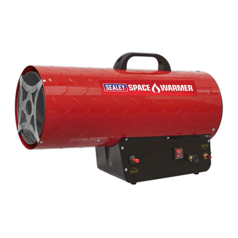
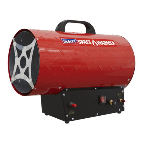
  9. Sealey LP35.V5 User manual

Sealey LP35.V5 User manual

Cable
Restraint
Brown
Live
Connection
1.1. PLUG & MAINS POWER SUPPLY
 WARNING! It is the responsibility of the owner and the operator to read, understand and comply with the following:
You must check all electrical products, before use, to ensure that they are safe. You must inspect power cables, plugs, sockets and any other
connectors for wear or damage. You must ensure that the risk of electric shock is minimised by the installation of appropriate safety devices.
A Residual Current Circuit Breaker (RCCB) should be incorporated in the main distribution board. We also recommend that a Residual Current
Device (RCD) is used. It is particularly important to use an RCD with portable products that are plugged into a supply which is not protected by an
RCCB. If in any doubt consult a qualified electrician. You may obtain a Residual Current Device by contacting your Sealey dealer.
You must also read and understand the following instructions concerning electrical safety.
NOTE: 110 volt heaters are usually operated by connecting to a transformer or a generator. Check to ensure all supply equipment is compatible
with the rating of the heater.
1.1.1. The Electricity at Work Act 1989 requires all portable electrical appliances, if used on business
premises, to be tested by a qualified electrician, using a Portable Appliance Tester (PAT), at least
once a year.
1.1.2. The Health & Safety at Work Act 1974 makes owners of electrical appliances responsible for
the safe condition of those appliances and the safety of the appliance operators. If in any doubt
about electrical safety, contact a qualified electrician.
1.1.3. Ensure that the insulation on all cables and on the appliance is safe before connecting it to the
power supply. See 1.1.1. and 1.1.2. and use a Portable Appliance Tester.
1.1.4. Ensure that cables are always protected against short circuit and overload.
1.1.5. Regularly inspect power supply cables and plugs for wear or damage and check all connections
to ensure that none is loose.
1.1.6. Important: Ensure that the voltage marked on the appliance matches the power supply to be
used and that the plug is fitted with the correct fuse - see fuse rating on right.
1.1.7. Important: For use with a 110 volt supply - ensure that the 110 volt transformer or generator
is adequately rated.
1.1.8. DO NOT pull or carry the appliance by the power cable.
1.1.9. DO NOT pull the plug from the socket by the cable.
1.1.10. DO NOT use worn or damaged cables, plugs or connectors. Immediately have any faulty item
repaired or replaced by a qualified electrician. When an ASTA/BS approved UK 3 pin 13 amp
plug or 110 volt plug is damaged, cut the cable just above the plug and dispose of the plug safely.
Fit a new plug according to the following instructions (UK only - see diagrams on right).
a) Connect the GREEN/YELLOW earth wire to the earth terminal ‘E’.
b) Connect the BROWN live wire to the live terminal ‘L’.
c) Connect the BLUE neutral wire to the neutral terminal ‘N’.
d) After wiring, check that there are no bare wires, that all wires have been correctly
connected, that the cable outer insulation extends beyond the cable restraint and that
the restraint is tight.
1.1.11. If an extension reel is used it should be fully unwound before connection. A reel with an RCD fitted
is preferred since any appliance plugged into it will be protected. The cable core section is important and should be at least 1.5mm2, but
to be absolutely sure that the capacity of the reel is suitable for this product and for others which may be used in the other output sockets,
we recommend the use of 2.5mm2section cable.
INSTRUCTIONS FOR:
PROPANE HEATERS
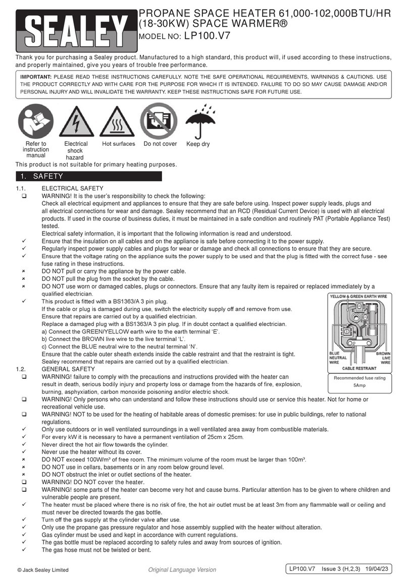
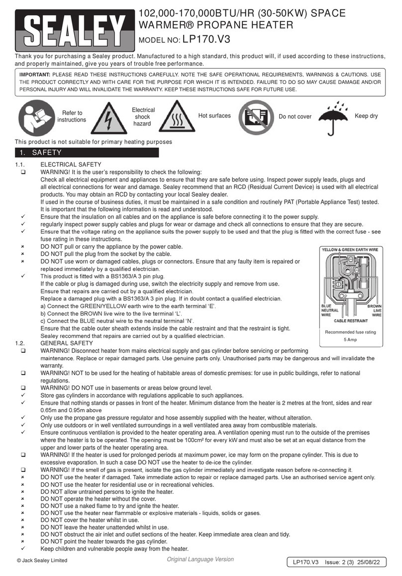
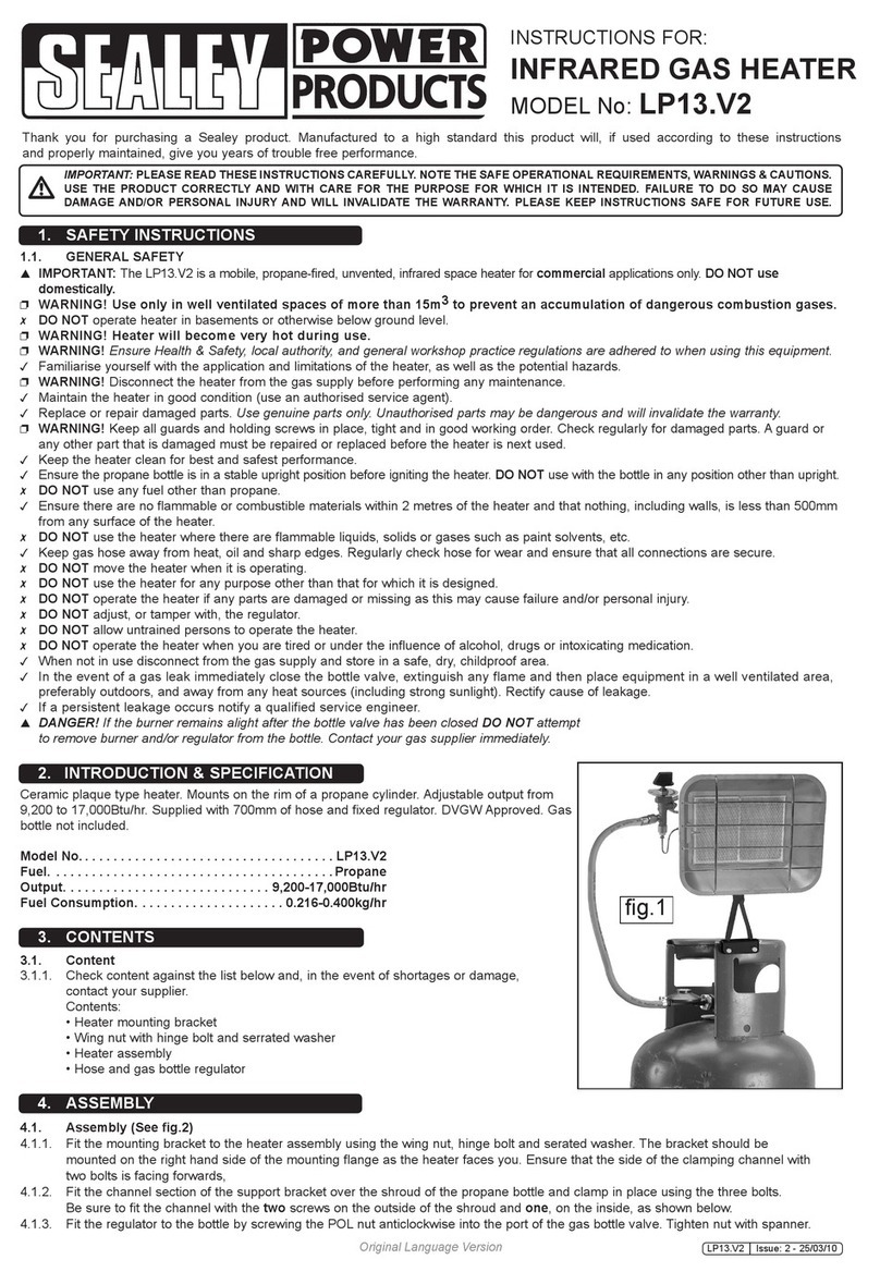
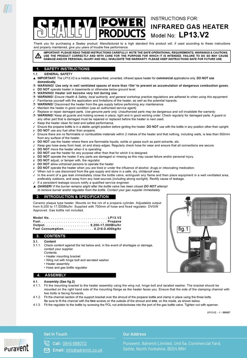
Thank you for purchasing a Sealey Propane Heater. Manufactured to a high standard this product will, if used according to these instructions
and properly maintained, give you years of trouble free performance.
1. SAFETY INSTRUCTIONS
IMPORTANT: PLEASE READ THESE INSTRUCTIONS CAREFULLY. NOTE THE SAFE OPERATIONAL REQUIREMENTS, WARNINGS AND CAUTIONS.
USE THIS PRODUCT CORRECTLY AND WITH CARE FOR THE PURPOSE FOR WHICH IT IS INTENDED. FAILURE TO DO SO MAY CAUSE DAMAGE
AND/OR PERSONAL INJURY AND WILL INVALIDATE THE WARRANTY. PLEASE KEEP INSTRUCTIONS SAFE FOR FUTURE USE.
Models: LP35.V5, LP70, LP80.V4, LP100.V2, LP145.V2, LP200.V3 & LP300.V4
1.2. GENERAL SAFETY
 WARNING! Disconnect heater from mains supply before servicing or performing maintenance. Replace or repair damaged parts. Use genuine
parts only. Unauthorised parts may be dangerous and will invalidate the warranty.
 Store gas cylinders in accordance with regulations applicable to such appliances.
 Ensure nothing is standing or passing in front of the heater. Mandatory minimum distance from the heater is 1mtr.
 Use the supplied pressure regulator only.
 Ensure continuous ventilation is provided to the heater operating area. A ventilation opening must run to the outside of the premises where the heater is
to be operated. The opening must be 25cm2for every kW and must also be set at an equal distance from the upper and lower parts of the heater operating area.
 Ensure that the heater is correctly turned off when not in use.
 DO NOT use the heater if damaged. Take immediate action to repair or replace damaged parts. Use an authorised service agent only.
 DO NOT allow untrained persons to ignite the heater.
 DO NOT operate the heater without the cover.
 DO NOT exceed the 100W/mtr3limit considering the volume of the empty operating area.
 DO NOT use a naked flame to try and ignite the heater.
 DO NOT use the heater near flammable material - liquids, solids or gases.
 DO NOT obstruct the air inlet and outlet sections of the heater.
 DO NOT point the heater at the gas cylinder.
 Keep the heater clean and in good working order and store in a safe area, out of the reach of children.
WARNING! If the heater is used for prolonged periods at maximum power, ice may form on the propane cylinder. This is due to excessive
evaporation. In such a case DO NOT use the heater to de-ice the cylinder.
Blue
Neutral
Wire
Yellow & Green
Earth Wire
Cable
Restraint
Brown
Live
Wire
Blue
Neutral
Connection
Yellow &
Green
Earth Wire
Connection
FUSE RATING 13 AMP
LP35.V5, LP70, LP80.V4, LP100.V2, LP145.V2, LP200.V3 & LP300.V4 - 2 - 210108
3. INSTALLATION
Note: If you use a small gas cylinder the heater may not operate at maximum efficiency. We recommend the use of two or more cylinders
linked in parallel to achieve maximum continuous efficiency (fig. 1).
3.1. Setting heater supply voltage (LP100, LP145, LP200 & LP300 only)
3.1.1. Locate the supply voltage selector panel (fig. 2), on the side of the base.
3.1.2. If the correct supply voltage is NOT shown, remove the two securing screws.
3.1.3. Remove the cover panel and select the required switch position as shown in fig. 3.
Note: The moulded design of the cover panel ensures that the selected voltage is visible.
3.1.4. Refit the cover panel using the two securing screws.
3.2. Connections
3.2.1. Check heater and gas cylinder to ensure that they are in good condition. If not, stop and contact your supplier immediately.
3.2.2. Site the heater and gas cylinder in the operational area.
3.2.3. Connect the heater to an electric socket, ensuring that the machine is correctly earthed. See safety instructions.
3.2.4. Connect the gas supply hose to the fixed pressure regulator and connect the regulator to the gas cylinder.
3.2.5. Gradually open the tap of the gas cylinder. Check hose and fittings for gas leaks.
WARNING! DO NOT USE A NAKED FLAME! To check for leaks, we recommend the use of a foamy soap solution.
2. TECHNICAL SPECIFICATIONS
fig. 2 fig. 3
4. IGNITION
IMPORTANT: To ensure continuous ventilation to the heater area, a ventilation opening must connect to the outside of the premises where the heater is to
operate. The opening must be 25cm2for every kW, and must be set at an equal distance from upper and lower parts of heater operating area.
4.1 Switch Heater On
4.1.1. Turn the fan switch to position “I” and check that the fan starts running (fig. 4).
4.1.2. Push the gas valve button in and hold, then press repeatedly on the ignition lighter switch until the flame ignites (fig. 5).
4.1.3. After the flame lights, and the heater starts, keep the gas valve button pushed in for a further 10 seconds (fig. 6).
4.1.4. If the heater stops when the gas valve button is released, leave the fan on but wait for one minute and repeat the starting operation,
after which hold the gas valve in for longer than 10 seconds before releasing.
4.1.5. The heat output is controlled by adjusting the gas pressure (not LP35 and LP70 as these have a fixed output). Turn the gas valve knob
located at the rear of the base, anti clockwise to reduce the pressure and heat and clockwise to increase the pressure and heat (fig. 7).
4.2. Switch Heater Off
4.2.1. Shut off the gas cylinder tap. Allow the fan to continue running until the flame shuts down, then turn the fan switch to position “O”.
LP35.V5, LP70, LP80.V4, LP100.V2, LP145.V2, LP200.V3 & LP300.V4 - 2 - 210108
LP35 LP70 LP80 LP100
Output (Propane): 10.0kW 17.5kW 16.5-25.6kW 12.5-31.2kW
Output (EN1596): 10.8kW 19.0kW 17.6-29.0kW 15.0-39.0kW
Output (Propane): 35,000Btu/hr 59,710Btu/hr 56,300-87,400Btu/hr 42,000-106,400Btu/hr
Output (EN1596): 36,880Btu/hr 64,830Btu/hr 60,000-99,000Btu/hr 51,000-131,800Btu/hr
Air Flow: 300mtr3/hr 300mtr3/hr 550mtr3/hr 750mtr3/hr
Fuel Consumption: 0.8kg/h 1.35kg/hr 1.14-1.77kg/hr 1.0-2.46kg/hr
Electrical Input: 230V - 0.3A 230V - 0.3A 230V - 0.8A 110/230V - 1.5/0.72A
LengthxWidthxHeight: 390x180x270mm 450x220x285mm 500x250x440mm 530x280x400mm
Fuel: Propane Propane Propane Propane
Heated Volume: 8,750ft317,500ft320,000ft326,000ft3
LP145 LP200 LP300
Output (Propane): 26.6-43.5kW 28.1-58.5kW 37.7-82.2kW
Output (EN1596): 33.2-54.5kW 34.5-77.0kW 46.5-102.2kW
Output (Propane): 90,000-148,500Btu/hr 96,500-200,000Btu/hr 130,000-280,500Btu/hr
Output (EN1596): 113,000-186,000Btu/hr 118,700-263,000Btu/hr 160,000-348,900Btu/hr
Air Flow: 850mtr3/hr 1800mtr3/hr 2450mtr3/hr
Fuel Consumption: 2.09-3.41kg/hr 2.12-4.64kg/hr 2.82-6.5kg/hr
Electrical Input: 110/230V - 1.5/0.72A 110/230V - 1.3/0.65A 110/230V - 1.3/0.65A
LengthxWidthxHeight: 690x280x400mm 780x370x520mm 925x370x520mm
Fuel: Propane Propane Propane
Heated Volume: 37,000ft350,000ft370,000ft3
fig. 1
fig. 4 fig. 5 fig. 6
 WARNING! If the flame shuts down during operation, before repeating the ignition operations make sure the fan is not jammed, and the air inlet
and outlet are completely free of obstructions. If the flame shuts off during normal operation due to overheating the cause of the problem must be
determined and corrected before repeating the ignition procedure.
fig. 7
The heater may also be used as a cool air fan, as follows:
5.1. Remove the gas supply hose and plug the heater into the mains electrical power supply.
5.2. Switch on the fan. The unit will now blow out cool air only.
5. COOL AIR FAN
6. MAINTENANCE
8. DECLARATION OF CONFORMITY
WARNING! Before commencing service or maintenance disconnect the unit from the electrical power and the gas supply. Use authorised parts
only.
Unauthorised parts may be dangerous and will invalidate the warranty.
6.1. Check the gas supply hose condition and change if necessary.
6.2. Check the starting electrode gap (fig. 8).
6.3. Check the ignition unit, safety thermostat, and thermocouple condition
and ensure that they are clean.
 Caution: Wear safety goggles to perform this operation.
6.4. Clean inside the heater unit and the fan blade with compressed air.
fig. 8 5mm
7. TROUBLESHOOTING
Declaration of Conformity We, the sole importer into the UK, declare that the products listed here are in conformity with the following standards and directives.
For Jack Sealey Ltd. Sole importer into the UK of Sealey Power Products.
21st January 2008
Propane Heaters
LP35, LP70, LP80, LP100, LP125, LP200 & LP300
2006/95/EC Low Voltage Directive
2004/108/EC EMC Directive
93/68/EEC CE Marking Directive
Gas Appliances (Safety) Regulations 1992
2006/42/EC Machinery Directive
LP35.V5, LP70, LP80.V4, LP100.V2, LP145.V2, LP200.V3 & LP300.V4 - 2 - 210108
NOTE: It is our policy to continually improve products and as such we reserve the right to alter data, specifications and component parts without prior notice.
IMPORTANT: No liability is accepted for incorrect use of this equipment.
WARRANTY: Guarantee is 12 months from purchase date, proof of which will be required for any claim.
INFORMATION: For a copy of our latest catalogue and promotions call us on 01284 757525 and leave your full name and address, including postcode.
Signed by Mark Sweetman
The construction files for these products are held by the Manufacturer and may be inspected, by a
national authority, upon request to Jack Sealey Ltd.
01284 757500
01284 703534
sales@sealey.co.uk
Sole UK Distributor
Sealey Group,
Bury St. Edmunds, Suffolk.
www.sealey.co.uk
Web
email
PROBLEM POSSIBLE CAUSE SOLUTION
The fan motor does not work 1. There is no electrical supply.
2. The motor has locked.
1. Check mains power supply, wire, plug, fuse.
2. Unlock the motor with appropriate tool.
The ignitor does not spark 1. Electrode has the wrong gap.
2. Faulty connection.
1. Check and reset the electrode to the correct position (fig. 7).
2. Check and connect correctly the ignitor and the electrode.
No gas flow to the burner 1. The cylinder gas tap is closed.
2. The cylinder is empty.
3. Gas leaks from the supply.
1. Open the gas tap.
2. Replace the cylinder.
3. Remove and clean the nozzle, check for leaks by using a
foamy soap only DO NOT USE FLAME to find leak.
The burner starts, but it stops as
the gas valve is released.
1. The thermocouple is not warm enough.
2. The safety override has activated
because the fan does not work.
1. Repeat the starting operation keeping the button pushed for
a longer time
2. See above “Motor does not work”
The heater stops during operation 1. Excessive gas supply.
2. Insufficient air flow.
3. Insufficient gas due to ice formation
on the cylinder.
1. Check the pressure reducer, and replace if necessary.
2. Check that the motor is working correctly.
3. Check and if necessary use a larger gas cylinder or multiple
cylinders connected parallel.

This manual suits for next models

6

Other Sealey Gas Heater manuals

Sealey Space Warmer LP170 User manual

Sealey

Sealey Space Warmer LP170 User manual

Sealey LP14 User manual

Sealey

Sealey LP14 User manual

Sealey LP100.V7 User manual

Sealey

Sealey LP100.V7 User manual

Sealey LP170.V3 User manual

Sealey

Sealey LP170.V3 User manual

Sealey LP13.V2 User manual

Sealey

Sealey LP13.V2 User manual

Sealey LP351 User manual

Sealey

Sealey LP351 User manual

Sealey LP100.V7 User manual

Sealey

Sealey LP100.V7 User manual

Sealey CH4200.V2 User manual

Sealey

Sealey CH4200.V2 User manual

Sealey LPH35 User manual

Sealey

Sealey LPH35 User manual

Sealey POWER PRODUCTS LP13.V2 User manual

Sealey

Sealey POWER PRODUCTS LP13.V2 User manual

Sealey LP14 User manual

Sealey

Sealey LP14 User manual

Sealey LP13 User manual

Sealey

Sealey LP13 User manual

Sealey SPACE WARMER LP100.V6 User manual

Sealey

Sealey SPACE WARMER LP100.V6 User manual

Sealey CH4200.V3 User manual

Sealey

Sealey CH4200.V3 User manual

Popular Gas Heater manuals by other brands

FMI MF42INE OWNER'S OPERATION AND INSTALLATION MANUAL

FMI

FMI MF42INE OWNER'S OPERATION AND INSTALLATION MANUAL

Desa Medallion MR10NT OWNER'S OPERATION AND INSTALLATION MANUAL

Desa

Desa Medallion MR10NT OWNER'S OPERATION AND INSTALLATION MANUAL

Vermont Castings RAD- VTBB Installating and operation manual

Vermont Castings

Vermont Castings RAD- VTBB Installating and operation manual

BuckMaster 1130 manual

BuckMaster

BuckMaster 1130 manual

Astria 126851-01 Installation and operation instructions

Astria

Astria 126851-01 Installation and operation instructions

Space-Ray RFPA21A-N6 Installation and operation instructions

Space-Ray

Space-Ray RFPA21A-N6 Installation and operation instructions

Pakole ZENIT 80+ Series user manual

Pakole

Pakole ZENIT 80+ Series user manual

Italkero Falo Evo User manual and assembly instructions

Italkero

Italkero Falo Evo User manual and assembly instructions

Bryant 574B user manual

Bryant

Bryant 574B user manual

Desa Comfort Glow CGB35P OWNER'S OPERATION AND INSTALLATION MANUAL

Desa

Desa Comfort Glow CGB35P OWNER'S OPERATION AND INSTALLATION MANUAL

White Mountain Hearth LS-18FAC-1 Installation instructions and owner's manual

White Mountain Hearth

White Mountain Hearth LS-18FAC-1 Installation instructions and owner's manual

Heat & Glo ST-HVBI-AU Installation and operation instructions

Heat & Glo

Heat & Glo ST-HVBI-AU Installation and operation instructions

Procom Lost River PCILVFD18-1 installation instructions

Procom

Procom Lost River PCILVFD18-1 installation instructions

Desa 30 OWNER'S OPERATION AND INSTALLATION MANUAL

Desa

Desa 30 OWNER'S OPERATION AND INSTALLATION MANUAL

Aletra ATLX 55 Installation and maintenance manual

Aletra

Aletra ATLX 55 Installation and maintenance manual

FMI TF18NR OWNER'S OPERATION AND INSTALLATION MANUAL

FMI

FMI TF18NR OWNER'S OPERATION AND INSTALLATION MANUAL

Modine Manufacturing PDP Installation and service manual

Modine Manufacturing

Modine Manufacturing PDP Installation and service manual

Brant Radiant Heaters QTS Series manual

Brant Radiant Heaters

Brant Radiant Heaters QTS Series manual

manuals.online logo
manuals.online logoBrands
  • About & Mission
  • Contact us
  • Privacy Policy
  • Terms and Conditions

Copyright 2025 Manuals.Online. All Rights Reserved.