Grand Canyon Gas Logs GCRK User manual

Page 1 of 6
GCRK
Manual On/Off Remote Control with Timer for Millivolt Valve
Installation and Operating Instructions
IF YOU CANNOT READ OR UNDERSTAND THESE INSTALLATION INSTRUCTIONS. DO NOT ATTEMPT TO INSTALL OR
OPERATE
This Manual on/off remote control with Timer transmitter is designed to be used with millivolt valve gas
appliances. It can be operated on/off from the transmitter or turned on and off manually from the receiver.
CONTENTS OF KIT
Description
Quantity
Transmitter
1
GCRK Timer remote control Transmitter
1
Receiver Box
1
Slide Button-Black and White Color (On/RS/Off)
2
Wall Cover Plate-Black and White Color
2
Battery Door- Black and White Color
2
Plug-In Wiring Assembly – 22” Inches
1
Installation Instructions
1
#6 3/4 Screws (for Wall Cover Plate and Remote control)
4
#6 3/4 Screws (for fireplace system control covers)
Plastic wall anchors (for installing transmitter)
2
2
NOTE: Due to the sensitive temperature monitoring components in the transmitter, it is necessary to allow the
transmitter to stabilize to room temperature before accurate room temperature are displayed, If the transmitter is
activated from a severe cold condition allow 15 minutes for accurate temperature reading to appear on the LCD.
WARNING
Important Safety Information
•Read this manual thoroughly prior to installing, programming or operating any remote control.
•This remote-control system is designed for use with a millivolt or 24V gas valve system. Do not use
this remote-control system on applications with voltages above 24 Volts AC/DC and 1 amp current.
•This remote-control system requires two (2) “AAA” and four (4) “AA” alkaline batteries to power the
transmitter and receiver.
•Turn appliance OFF (at the appliance or remote receiver) if you are away from your house for a
long period of time.
FEATURES/SPECIFICATIONS
•Easy Operate Manual on/off and Timer Control
•Battery Powered Transmitter and Receiver
•Low battery Indication
•Select Between °C and °F display
•Child Proof Lock-out
•16 Security Codes
•Quick Disconnect Wiring Assembly

Page 2 of 6
WARNING
Turn appliance OFF and allow to cool before installing or servicing. DO NOT connect
110-120 VAC wiring to the millivolt gas control valve. The remote operator must be installed
exactly as outlined in these instructions. Read all instructions completely before attempting
installation. Follow instructions carefully during installation. Any modification of
components will void the warranty and may cause a fire hazard.
Transmitter:
Installing Batteries:
The remote transmitter uses two (2) “AAA” batteries. To install batteries:
1. Press down the battery door and remove the battery door.
2. Install uses two (2) “AAA” batteries as indicated on transmitter.
3. Close the battery door by snapping in place.
4. The batteries should be replaced when the low battery indicator display in LCD.
5. When both batteries are installed, the transmitter will initialize for 1 seconds and then is ready for use.
LEARNING TRANSMITTER TO RECEIVER
1. The transmitter privacy (DIP) Switches are preset at the factory. Setting the 4 bits DIP Switches on
transmitter to select a security code.
2. Put the receiver slide switch to “RS” location. Using a small screwdriver or end of a paper clip gently press
and hold the ‘LEARN ‘button on the receiver to accept the transmitter security code upon initial use, when you
release the LEARN button the receiver will emit an audible 3 “beep” sounds
3. After the receiver emits 3 “beep” sounds. Press the transmitter “ON “or “OFF” button and release at once.
The receiver will emit several beeps indicating that the transmitter’s code has been accepted into the receiver.
4. If you are unsuccessful in matching the security code on the first attempt repeat step 1-3
Transmitter
Dip Switch (Default as below, can be setting by user) Receiver
KEY SETTINGS
1. ON - - ------Turns appliance ON.
2. OFF - -----Turns appliance OFF.
3. TIMER - --Changes unit from manual mode to timer mode.
4. SET - ------Adjusts timer setting.
WAR
NING
Do not use two (2) or more remote-control systems in the same area with the same dip switch
settings, as they will communicate with each other. This may cause the appliances to
malfunction.

Page 3 of 6
OPERATIONS:
The GCRK Remote Control has two (2) operating modes: Manual and Timer. (15 min. -180 min. in 15 minutes
increments). The max setting time is 180 min.
The transmitter will operate the remote receiver from 1 foot to 30 feet. The distance is reduced when batteries
are low or when the receiver is inside a metal enclosure.
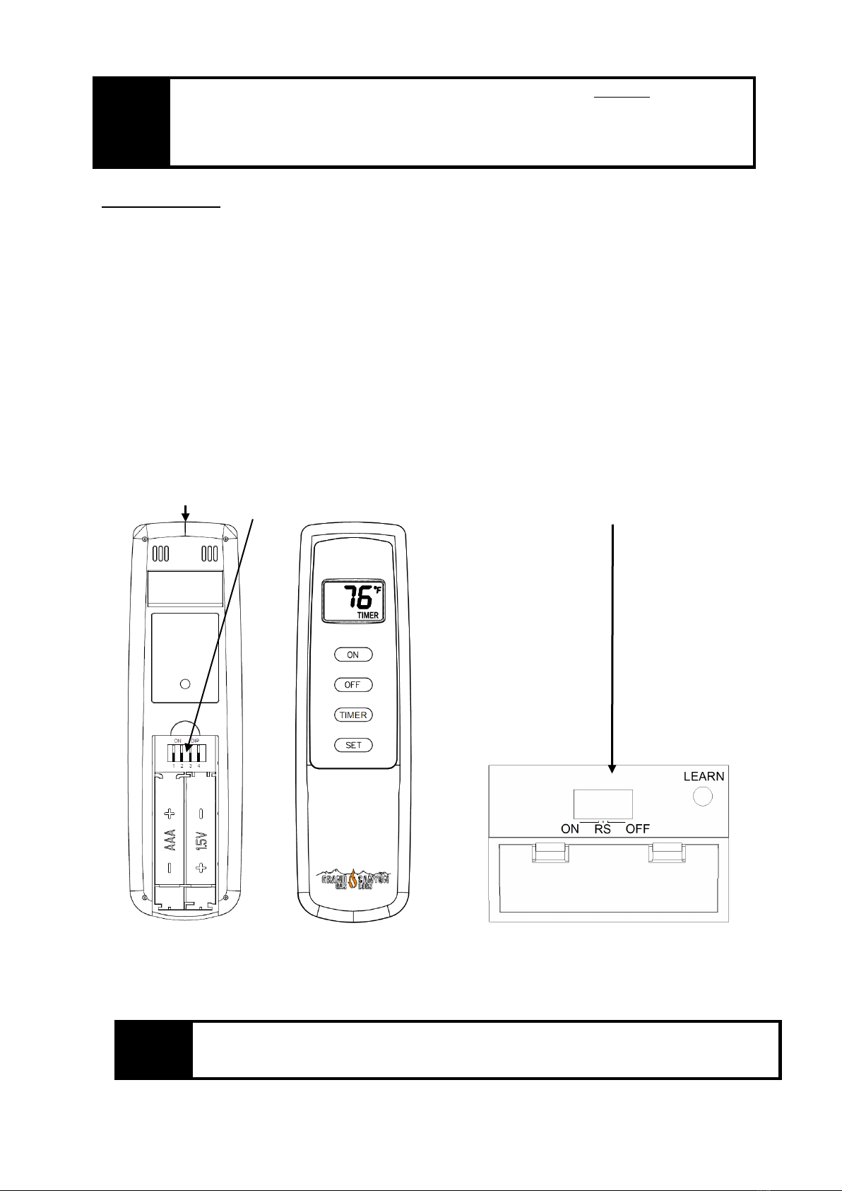
Initial startup:
1. After initial power up the transmitter is reset.
2. During system reset, all features of the LCD will be visible. After one second, the LCD
will be initialized. A typical reset display is shown right. After reset the transmitter is
operating. The real room temperature is shown as right.
Manual Mode:
1. Press the” ON” button once to turn on the appliance.
2. Press the” OFF” button once again to turn off the appliance.
3. Press” ON” and” OFF” button at same time for 1 second to select between °C and °F display.
Timer mode:
1. Press the ”ON” button to start the appliance
2. Press the “TIMER” button. The LCD screen will show the word ‘SET’.
3. Press the “SET” button until the desired time is reached (15min-
180min.in15minute increments). The max setting time is 180 min.
4. Press the “OFF” button to turn OFF the timer, and the appliance
Low-battery detection:
1. When the battery voltage of remote less than 2.2V, the low battery icon will appear on the LCD screen.
The battery will be checked every3 minute. If the battery voltage of remote is less than 1.8V, the remote
will send the flame off command to the receiver and only low battery icon display on the LCD,
Change the battery before the battery is too weak for normal operation. TURN THE UNIT OFF
BEFORE REPLACING BATTERIES.
Child-proof protection:
1. Press and hold ”ON” and ”TIMER” button at same time for 5 seconds to activate child-
proof mode. The letters CP will appear in the TEMP frame on the LCD screen.
2. The remote control will not work until child-proof mode is deactivated by pressing the
”ON” and” TIMER” buttons at same time for 5 seconds again to exit child-proof mode.
Transmitter Wall Clip
The transmitter can be hung on a wall using the clip provided. If the clip is
installed on a solid wood wall, drill 1/8” pilot holes and install with the screws
provided. If it is installed on a plaster/wallboard wall, first drill two 1/4” holes into
the wall. Then use a hammer to tap in the two plastic wall anchors flush with the
wall; then install the screws provided.

Page 4 of 6
WAR
NING
Make sure that the wires do not contact the appliances any place other than at the terminals.
Exposure to temperatures higher than 250℉(105℃) may cause the receiver to malfunction or
cause a fire hazard.
Receiver:
Begin by installing (4) AA-size batteries. Slide open the battery cover on receiver. It is
recommended that ALKALINE batteries always be used for this product. Be sure the
batteries are installed with the (+) and (-) ends facing the correct direction. Close battery
cover
Installation The remote receiver can be either wall-mounted in a standard plastic switch
box (not metal) or placed on or near the fireplace hearth. Preferably, the remote receiver
should be wall-mounted in a plastic switch box, as this will protect its electronic components
from the heat produced by the gas appliance. The remote receiver should be kept away from
temperatures exceeding 130ºF. Battery life is also significantly shortened if batteries are
exposed to temperatures 130ºF or higher. Before installation make sure the remote receiver slide switch is in the
OFF position.
Wall Mount When wall mounting the remote receiver, longer wires (not included) are required to connect to
the gas valve or electronic module. These wires must: Be at least 18 Gauge (AWG)
Hearth Mount The remote receiver may be placed on the fireplace hearth or under the fireplace behind the
control access panel. Use the wires attached to the remote receiver to connect to the gas valve or an on/off
switch (included piggyback connectors have both male & female terminals for flexibility). Be sure that the
connectors do not touch each other or other bare metal surfaces.
Wiring the Receiver to Valve

Page 5 of 6
Connect one wire from the remote receiver to the TH terminal on the gas valve Connect the other wire from the
remote receiver to the TH/TP terminal on the gas valve
Slide Switch:
1. ON position: the system will remain on until the slide switch is placed in the OFF or REMOTE position.
2. REMOTE position: the system will only operate if the remote receiver receives a signal from the transmitter.
3. OFF position: the system is off. The slide switch should be placed in the OFF position if you will be
away for an extended period of time. If the remote receiver is mounted out of children’s reach, the OFF
position also functions as a safety device by both turning the system off and rendering the receiver inoperable.
Testing Your New Remote System
1. Light your gas appliance following the appliance lighting instructions that come with the appliance. Confirm
that the pilot light is on; it must be in operation for the remote control to operate the main gas valve. Appliance
control knob must be in the ON position. Appliance ON/OFF switch must be in ON position.
2. Slide the 3-position button on the remote receiver to the ON position. The main gas flame should ignite.
3. Slide the button to OFF. The flame should extinguish (the pilot light will remain on).
4. Slide the button to REMOTE (the center position), then press the transmitter to turn the system to ON. The
main gas flame should ignite.
5. Press the transmitter to turn the system to OFF. The flame should extinguish (the pilot light will remain on).
TROUBLESHOOTING

Page 6 of 6
Symptom
Causes
Action
Battery icon on LCD on
transmitter.
Low Battery
Replace batteries.
LCD Display is blank
Low Battery
Check battery installation and replace
batteries.
Receiver emits the beep in
every minute
Low Battery
Replace batteries.
Appliance does not come
on.
1. DIP (Privacy) switch setting on
transmitter does not match receiver
1. Make sure the transmitter is matched to
the receiver.
2. Transmitter measures temperature
exceeding 99 degrees and shows
“HI” on LCD display.
2. Move transmitter to a cooler place and
wait until temperature drops below 99
degrees.
3. Distance between the transmitter
and receiver is more than 30 feet
3. Make sure the operating distance is less
than 30 feet
Receiver cannot receive
signal.
1.Receiver is installed in an enclosure
1. Make sure the receiver is not inside a
tight enclosure.
Table of contents
Popular Remote Control manuals by other brands

Universal Electronics
Universal Electronics CERVINO user manual

WAREMA
WAREMA WMS Wall-mounted transmitter basic Operating and installation instructions

Tactic
Tactic TACTIC TTX650 instruction manual

Sealey
Sealey 39wireless user manual

Panasonic
Panasonic CZ-RTC2 User functions guide

dji
dji Matrice600 Series user guide