Grandbeing MX0808-311 User manual

Model No.: MX0808-311
Operating Instructions
Thanks for purchasing our product.
Please be sure to read this instruction manual
carefully before using our product.

Introduction
MX0808-311 is an 8-by-8 DVI/HDMI true matrix. It allows any of the eight
source (Blue-Ray player, HD DVD player, satellite receiver, game system, etc.)
to be routed to any of the eight displays simultaneously, no matter the source is
HDCP or not. Users can choose several different ways to control the matrix: by
using infrared extension receiver, RS232, RS485, and LAN and supplied
remote control. IR emitters in the matrix are for controlling the sources; the IR
control signal could be from remote locations via STP/UTP type HDMI
connection on the rear panel.
MX0808-311 has the ability of equalization and amplification to ensure HDMI
signal's transmission through long cable without quality loss. The transmission
distance of STP/UTP outputs reaches up to 50 meters under the vedio format
of 1080P, together with infrared control signal.
MX0808-311 offers solutions for digital entertainment center, HDTV retail and
show site, HDTV, STB, DVD and projector factory, noise, space and security
concerns, data center control, information distribution, conference room
presentation, school and corporate training environments.

Contents
HDMI Matrix .................................................................................................................................... 1
Product Overview ........................................................................................................................... 1
Features ........................................................................................................................................... 1
Notice................................................................................................................................................ 2
Package Contents............................................................................................................................ 3
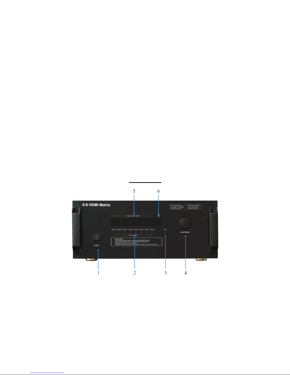
Panel Descriptions ........................................................................................................................... 3
Connections and Operations ........................................................................................................... 5
Operation.......................................................................................................................................... 6
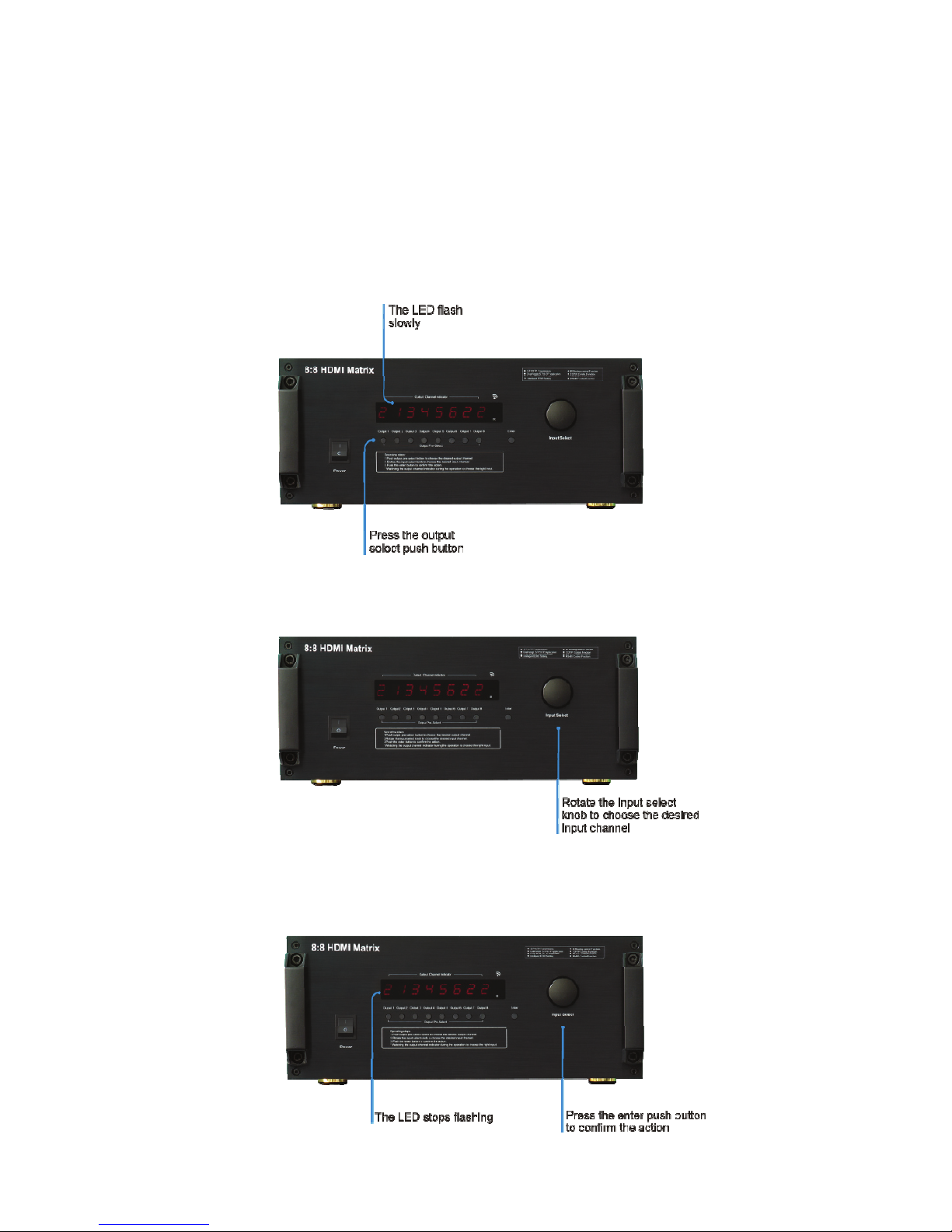
1. Operation on front panel. ............................................................................................................. 6
2. Control via IR remote. .................................................................................................................. 7
3. Control via RS232. ....................................................................................................................... 7
4. LAN control................................................................................................................................. 13
5. IR call back from remote locations to control the HDMI Matrix MX0808-311 .......................... 16
6. Instruction of TX IR..................................................................................................................... 16
7. DIP switch setting....................................................................................................................... 17
8. Reading and saving EDID data from display............................................................................. 18
9. Check the working status........................................................................................................... 20
Specifications ................................................................................................................................. 20
Typical Application ......................................................................................................................... 21
Maintenance................................................................................................................................... 21
Product Service .............................................................................................................................. 21
●Provided Service ......................................................................................................................... 21
●Mail-In Service............................................................................................................................. 22
●Warranty...................................................................................................................................... 22
●Warranty Limits And Exclusions ................................................................................................. 22


HDMI Matrix (Routing Type)
■Product Overview (Model Number: MX0808-311)
■Features
zAllows up to eight HDMI audio/video devices to be independently switched to eight HDMI
monitors, HDTV’s, or projectors.
zThe eight outputs could show the same or different source simultaneously no matter the
source is HDCP or not.
zEach output includes one HDMI A type connecter and a set of dual RJ-45 connecters as
the second mirrored HDMI output. The two outputs work simultaneously. The UTP output
supports both dual and single cat5e/cat6
zReading and saving EDID function from displays.
zSupport high definition resolutions, including 1080p, 1080i, 720p and other standard
video formats.
zEach port supports both HDMI and DVI inputs.
zWith extra infrared extension receiver.
zSix switching modes: panel buttons, local IR, IR call back from remote locations, RS232,
RS485 and Ethernet.
zEight IR emitters to control the HDMI sources.
zHDCP compliant.
zHDMI 1.3 version.
z3D support.

■Notice
We reserve the right to make changes in the hardware, packaging and any accompanying
documentation without prior written notice.
Warning
To reduce the risk of fire, electric shock or product damage:
1. Do not expose this apparatus
to rain, moisture, dripping or
splashing and that no objects
filled with liquids, such as vases,
shall be placed on the apparatus.
6. Clean this apparatus
only with dry cloth.
2. Do not install or place this unit
in a bookcase, built-in cabinet or
in another confined space.
Ensure the unit is well ventilated.
3. To prevent risk of electric
shock or fire hazard due to
overheating, do not obstruct
the unit’s ventilation openings
with newspapers, tablecloths,
curtains, and similar items.
4. Do not install near any heat
sources such as radiators, heat
registers, stoves, or other
apparatus (including amplifiers)
that produce heat.
5. Do not place sources of naked
flames, such as lighted candles,
on the unit.
7. Unplug this apparatus
during lightning storms or
when unused for long
periods of time.
8. Protect the power cord
from being walked on or
pinched particularly at
p
lu
g
s.
9. Only use attachments /
accessories specified by
the manufacturer.
10. Refer all servicing to
qualified service
personnel.

■Package Contents
①1x Main unit. P/N_MX0808-311.
②1 x 100~240V AC Power cable.
③1x Remote.
④ 1x IR RX (IR receiver cable).
⑤ 8X IR TX (IR emitter cable).
⑥ 1x USB to UART cable.
⑦1x RS232 to RS485 converter.
⑧Operating Instructions. P/N_INS MX0808-311.
⑨Mounting ears.
NOTE: PART NUMBER (Abbreviation as P/N).
■Panel Descriptions
Front Panel
1. Power switch.
2. Output selection push button (Use it to choose the output channel you want to change).
3. Action Confirmation button (Push the ‘Enter’ button to confirm the changing of input channel
to the output).
4. Input selection knob (Rotate it to select the input to the output).
5. LED indicator of input for output port 1 to 8.
6. IR window.

Back Panel
1. IR extension.
2. DIP switch setting.
3. IR emitter, corresponding to the Input port from 1 to 8.
4. RS485 port
5. LAN port.
6. RS232 port.
7. Power input.
8. Input ports 1 to 8.
9. Output 1 to 8 with HDMI and CAT5E.
10. ISP PORT.
NOTE: RS232 port and LAN port are for matrix control. The LAN port is connected to the computer via
cross UTP and connected to the router or switcher via direct UTP.

■Connections and Operations
1) Connect the HDMI input source ( such as HD-DVD/ PS3 /STB etc.)Into MX0808-311.
2) Connect the standard HDMI outputs ( such as HD-LCD, HD-DLP) into MX0808-311.
3) Connect two CAT-5E cables to both the STP/UTP outputs of MX0808 - 311 and inputs of
STP/UTP receiver ( such as EX0101-U31/33/51/53 etc). Please pay attention to the
sequence of the two cables, CAT5e-1-> CAT5e1, CAT5e-2- > CAT5e2. ( The cable
termination must follow the standard of EIA/TIA 568B, if Single UTP mode, just connect
CAT5E -2).
4) Connect the HDMI output ( such as : HD-LCD、HD-DLP ) into the STP /UTP receiver.
5) Connect the IR RX receiving cable into STP/UTP receiver IR RX and connect the IR TX
cable into MX0808-311 IR emitter.
6) Power on the input source you want to show. ( Keep the unused input power off,
otherwise it may interfere the normal display).
7) Connect the power supply into MX0808-311.
8) Turn on the power, when the LED panel stops flashing circularly, the initialization of the
matrix are ready.
9) Turn on the displays you want to watch.
10) Use the remote supplied or pushes the button on the front panel to choose input source, or
using infrared extension receiver, RS232, RS485 or LAN port to do the control.

■Operation
1. Operation on front panel.
First: Press the output select button to the output channel which you want to change. Then the
corresponding LED of the output channel will blink slowly.
Second: Rotate the input select knob to choose the desired input channel.
Third: Press the ‘Enter’ button to confirm the action. Then the LED stops blinking.

2. Control via IR remote.
NOTE: if the IR remote isn’t work, please press the”system code switch key”, but please do not put
the remote against the MX0808-311.
3. Control via RS232.
1) The Interface of MX0808-311 COM control.

2) The Message Window
2.1 Receive Window
The “receive window” will show the message received from MX0808. When you click the Control
Buttons ( see step 4) or send Control Command ( see 2.3) to MX0808, it will send out the
message about “operation results” as below:
2.2 Status Button
Click this button to read the status of MX0808. The status is about which input is selected by the
output.
2.3 Send Window
Input the control command in this window. The control command use ASCII.
.

2.4 Setting Button
Click this button to enter Setting menu. When you click this button it will read the current mode of
mx0808, if you want to change the mode, select the mode you want (They will be active
immediately but the Switch mode. The Switch mode was applied after re-cycle the power.
2.5 Set IP Button
Click this button to set IP address for nettle.
2.6 IR Set button
Click this button to set IR code for remote control. The device will enter ire set mode.
You can edit your ire code in this mode.

Step:
"1, Read the ire code first by pressing "Read Code” button.
"2, Select the code with cursor which you want to change.
"3, Press the button on your remote control with the remote against to the device. And the
selected code will change to this button code.
"4, when you finish it, click the "write code" button. It will write the new code onto device.
"5. Close the IR Code setting window. The device will enter normal mode from IR setting
mode.
Notices: All the codes have to be filled in and no blank is allowed. The same data codes are not
allowed, and every data code should be different.
2.6-1 Read Code button
Click this button to take out the current ire code form the device,
2.6-2 Write Code button
Click this button to write the codes onto the device.
3) The Com Status
3.1 connect state.

Connect state shows the com open or not. If it is open, the state is green. Otherwise, the state is
red.
3.2 com select.
ÆSelect which com you will use.
ÆConnect button.
The word on this button will change when the connection state changes. If the word is
“Disconnect”, then click this button, the com will be closed. If the word is “Connect”, then click this
button, the com will be opened.
4) Control command format
If user want to write his own control software, below are data format and baud rate setting.
Com port setting:
Baud Rate: 9600 bps
Data bits: 8 bits
Parity: None
Stop bits: 1 bit
Flow control: None
The command format as follow:
Cir + ‘_’ + code + ‘ ’↙
“Cir” is the key word, ‘_’ is Space, “Code” is the Control code, and ‘↙’ is carriage return. For
example:
“Cir 39↙” (hex: 63 69 72 20 33 39 0D 0A), when the mx0808 received this command, it will
change the Outport4 status to the next input port. ( “c”-0x63,”I”-0x69,”r”-0x72,”
“-0x20,”3”-0x33,”9”-0x39, ‘↙’-0x0d0a)
5) Control code (MX0808-311)
Outport1 <“08” >“09”

1“00” 2“01” 3“02” 4“03”5“04” 6“05”7“06”8“07”
Outport2 < “18” > “19”
1 “10” 2 “11” 3 “12” 4 “13”5“14” 6“15”7“16”8“17”
Outport3 < “28” > “29”
1 “20” 2 “21” 3 “22” 4 “23”5“24” 6“25”7“26”8“27”
Outport4 < “38” > “39”
1 “30” 2 “31” 3 “32” 4 “33”5“34” 6“35”7“36”8“37”
Outport5 <“48” >“49”
1“40” 2“41” 3“42” 4“43”5“44” 6“45”7“46”8“47”
Outport6 < “58” > “59”
1 “50” 2 “51” 52” 4 “53”5“54” 6“55”7“56”8“57”
Outport7 < “68” > “69”
1 “60” 2 “61” 3“62” 4 “63”5“64” 6“65”7“66”8“67”
Outport8 < “78” > “79”
1 “70” 2 “71” 3 “72” 4 “73”5“74” 6“75”7“76”8“77”
When you send a control command to the MX0808, if succeed, it will feedback current output
port status to show which input port is selected. The return status format is as follows:
For example, if you send “cir 44↙” to MX0808,if succeeds, it will feedback “s55”, meaning
OutPut5 selects InPut5.

6) Read Status Command
The command length is 4 bytes.
bc + ‘_’ + ‘ ’↙
“bc” is the key word, ‘_’ is Space, ‘ ’ is carriage return.↙
When you send the read status command to MX0808, if succeeds, it will feedback the status of
all outputs. When you send “Bc” to MX0808, if succeed, it will feedback the current status of
MX0808.
For example, if you send "bc ↙"to MX0808,if succeeds, it will feedback
"s11\r\n" ,"s22\r\n" ,"s33\r\n" ,"s44\r\n" ,"s55\r\n" ,"s66\r\n" ,"s77\r\n" ,"s88\r\n" .it means that
the output 1 select the input 1, the output 2 selects the input 2, output 3 selects the input3,
output 4 selects the input 4, output 5 selects input 5, the output 6 selects the input 6, the output
7 selects the input 7, the output 8 selects the input 8.
7) Web password reset
The command length is 4 bytes.
rpw+ ‘↙’
“rpw” is the key word , ‘↙’ is carriage return.
When you send the Web password reset command to MX0808, if succeed, it will feedback "rpw",
and the web password will be set as "0000000000".
4. LAN Control.
Note: Use the direct UTP cable to connect with PC, or use cross cable to connect to the Ethernet
switcher
A.When NETCTL run on PC at the first time, it will create a file ‘NETCTL.TXT’. This file is
for device information’s backup. These information include MAC address of MX0808, IP
address, device name etc.
Double click NETCTL.exe to run NETCTL. It will search the device. If the device is a new one,
NETCTL will list it‘s IP address. If IP address appears, please click the button .
NETCTL will change the IP address to device name.

If you want to change the device name. Right-click the device name. A pull down menu will be
displayed. Click the item ‘Rename’ to rename it’s name.
B. Double click the device name, or click right button and click the ‘open’. A web browser
will be shown. The default password is "0000000000", input the password and login. The
device controller page will be displayed.

The right area is for device controlling. Click these buttons to control the device. It is the same as
using the remote controller. The left area shows which input ports are being chosen by the output
ports.
C. When ‘Assign IP’ is displayed, it means that the device has not been assigned IP
automatically. Double click this item. Or click right button and click ‘Assign IP’ on
the pull down menu. You can assign the IP address in the Assign IP dialog.
Click OK after assign the new IP and to return to the previous dialog. Click
and . The device can be displayed correctly.
ATTENTION:here assign IP is different from SetIP in COMCTL. SetIP in COMCTL is save the IP
address in flash, when the mx0808 power on, it will read the IP from flash and set it as static IP.
Assign IP function used when automatically obtain IP address failed. This assigned IP address
is not save in flash.

5. IR call back from remote locations to control the HDMI
Matrix MX0808-311. You can use the MX0808-311’s remote
through the IR RX of the UTP receiver to change the input
channel for the UTP out of the MX0808-311, just changing this
UTP output.
This function can be set on or off: press the output1 button and the output8 button at the same
time for about 3 seconds. The LEDs will display ‘IR ON’ or ‘IR OFF’. Push the ‘ENTER’ button or
wait for 3 seconds. MX0808-311 goes into normal working condition.
6. Instruction of TX IR.
The sequence of "TX IR1,TX IR2,TX IR3,TX IR4,TX IR5,TX IR6,TX IR7,TX IR8" one-to-one
correspond with "HDMI INPUT1,HDMI INPUT2,HDMI INPUT3,HDMI INPUT4, HDMI
INPUT5,HDMI INPUT6,HDMI INPUT7,HDMI INPUT8". When an output chooses certain input,
the call-back IR signal of RJ45 on this output port will choose the corresponding "TX IR" port to
send the signal out.
For example, OUTPUT1 chooses INPUT3, then the call-back IR signal of RJ45 on OUTPUT1 will
choose "TX IR3" to send the signal out.
Table of contents