Grandbeing MX0404-HE1 User manual

Model No.: MX0404-HE1
Operating Instructions
Thanks for purchasing our product.
Please be sure to read this instruction manual
Carefully before using our product.

Introduction
Grandbeing’s MX0404-HE1 is a 4-by-4 DVI/HDMI true matrix. It allows any
source (Blue-Ray player, HD DVD player, satellite receiver, game system, etc.)
to be shown on the any of the four displays simultaneously, no matter the
source is HDCP or not. Extra infrared receiver extension, IR emitter, RS232
and Ethernet port are supplied for remote control.
MX0404-HE1 has the ability of equalization and amplification to ensure HDMI
signal's transmission through long cable without quality loss.
MX0404-HE1 offers solutions for digital entertainment center, HDTV retail and
show site, HDTV, STB, DVD and projector factory, noise, space and security
concerns, data center control, information distribution, conference room
presentation, school and corporate training environments.

Contents
HDMI Matrix.....................................................................................................1
Product Overview ............................................................................................1
Features...........................................................................................................1
Package Contents............................................................................................3
Panel Descriptions...........................................................................................3
Front Panel......................................................................................................3
Back Panel.......................................................................................................4
Installation........................................................................................................4
Operation.........................................................................................................5
Specifications.................................................................................................16
Typical Application.........................................................................................17
Maintenance..................................................................................................18
Provided Service............................................................................................18
Mail-In Service...............................................................................................18
Warranty ........................................................................................................19
Warranty Limits and Exclusions.....................................................................19

Page 1
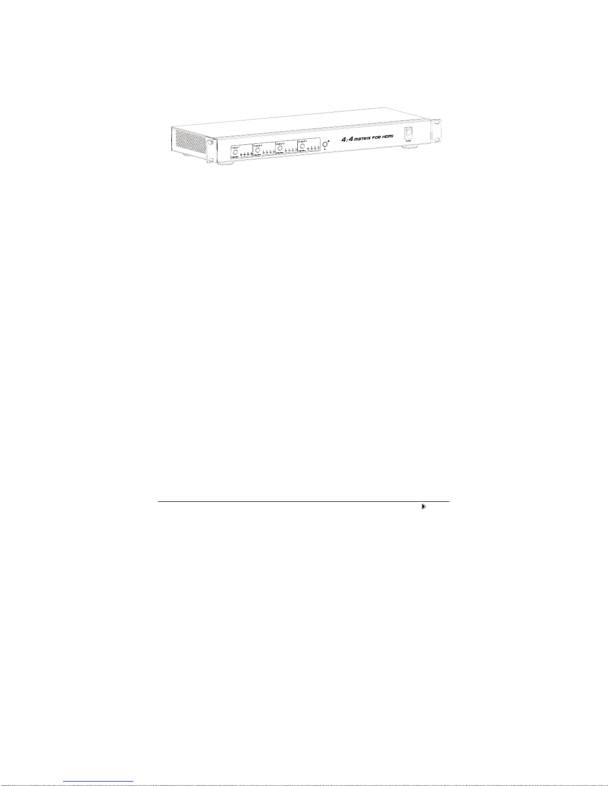
HDMI Matrix (Router Type)
■Product Overview (Model Number: MX0404-HE1)
■Features
zEasy to use, install in seconds.
zAllows up to four HDMI audio/video devices to be independently switched
to four HDMI monitors, HDTV’s, or projectors.
zThe four outputs could show the same or different source simultaneously
no matter the source is HDCP or not.
zThe four outputs are all include one HDMI-A output port and one HDBT
output port. They can output simultaneously.
zSupport high definition resolutions 1080p, 1080i, 720p and other standard
video formats.
zEach port supports HDMI or DVI inputs.
zWith extra infrared receiver extension.
zFive switching modes: panel buttons, local IR, IR call back from remote
rooms, RS232 and Ethernet.
zIR system could control the sources from the sinks or control the sinks
from sources.
zHDCP compliant.
zHDMI 1.3 version.
z3D support.

Page 2
"Notice
Grandbeing Inc. reserves the right to make changes in the hardware,
packaging and any accompanying documentation without prior written notice.
Warning
To reduce the risk of fire, electric shock or product damage:
1. Do not expose this apparatus
to rain, moisture, dripping or
splashing and that no objects
filled with liquids, such as vases,
shall be placed on the apparatus.
6. Clean this apparatus
only with dry cloth.
2. Do not install or place this unit
in a bookcase, built-in cabinet or
in another confined space.
Ensure the unit is well ventilated.
3. To prevent risk of electric
shock or fire hazard due to
overheating, do not obstruct
the unit’s ventilation openings
with newspapers, tablecloths,
curtains, and similar items.
4. Do not install near any heat
sources such as radiators, heat
registers, stoves, or other
apparatus (including amplifiers)
that produce heat.
5. Do not place sources of naked
flames, such as lighted candles,
on the unit.
7. Unplug this apparatus
during lightning storms or
when unused for long
periods of time.
8. Protect the power cord
from being walked on or
pinched particularly at
p
lu
g
s.
9. Only use attachments /
accessories specified by
the manufacturer.
10. Refer all servicing to
qualified service
personnel.

Page 3
■Package Contents
①Main unit. P/N_MX0404-HE1.
②12V/DC Power Supply. P/N_VDC01205.
③ 1x Remote... (Battery type: CR2025 3V).
④ 1x IR extension cable (38 KHz IR receiver cable, connect to IR Ext
sockets of MX0404-HE1).
⑤ 4x IR emitter cable (connect to IR emitter sockets of MX0404-HE1).
⑥4x IR receiver cable (from 30 KHz to 56 KHz IR receiver cable, connect to
IR receiver sockets of MX0404-HE1).
⑦ Operating Instructions. P/N_INS MX0404-HE1.
NOTE: PART NUMBER (Abbreviation as P/N).
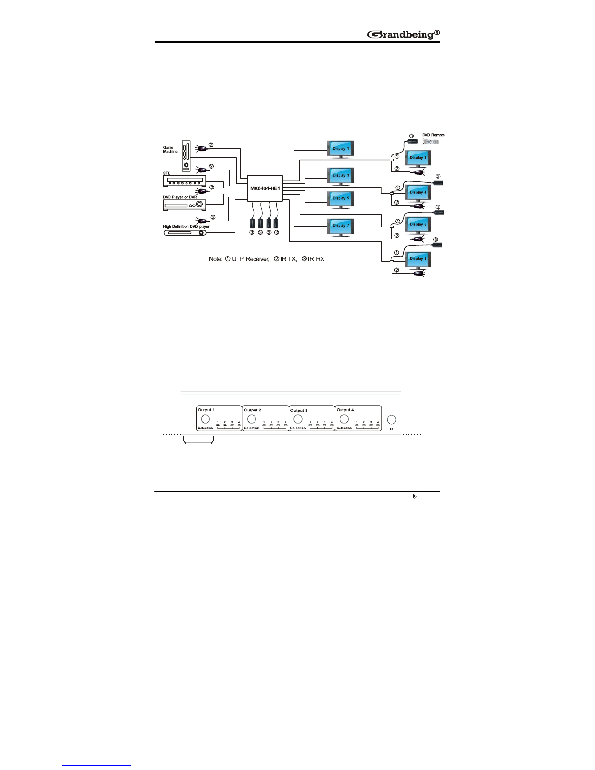
■Panel Descriptions
Front Panel
① Output selection and indicator of input for output port 1 to 4.
② IR window.
③ Power switch.

Page 4
Back Panel
① RS232 port.
② LAN port.
③ DIP switch for EDID setting.
④ Power input.
⑤ IR extension.
⑥ Output 1 and 2 with HDMI and HDBT.
⑦ Input ports 1 to 4.
⑧ Output 3 and 4 with HDMI and HDBT.
⑨ IR emitter sockets.
⑩IR receiver sockets.
NOTE: RS232 port and LAN port are for matrix control. The LAN port is connected to
the computer via direct UTP and connected to the router via cross UTP.
■Installation
①Connect the HDMI input sources ( such as HD-DVD, PS3, STB etc)
into MX0404-HE1.
② Connect the HDMI outputs ( such as HD-LCD, HD-DLP) into MX0404-
HE1.
③Use the HDMI cable to connect local HDMI sink device ( near to the
matrix) to MX0404-HE1. Use UTP cable to connect remote HDMI sink
devices to MX0404-HE1.
④Power on the input source you want to show.
Page 5
⑤Connect the power supply into MX0404-HE1 and turn on the display you
want to watch.
⑥ Use remote or push the button to choose input source. Extra infrared
receiver extension, IR emitter, RS232 port and Ethernet are supplied for
remote control.
■Operation
1. Front panel control
The MX0404-HE1 front panel control for switching inputs to the various outputs.
There are four groups of LEDs for each output port. The LED lit on the position
means that the output port selects this input as its source.
Page 6
2. Local IR remote control.
3. IR extender control
User can use the IR receiver cable to change the IR receiver position.
If controlling the MX0404-HE1 through the 1/8” (3.5 mm) input jack on the rear
panel, connect the IR cable directly to the matrix rear IR Ext socket.
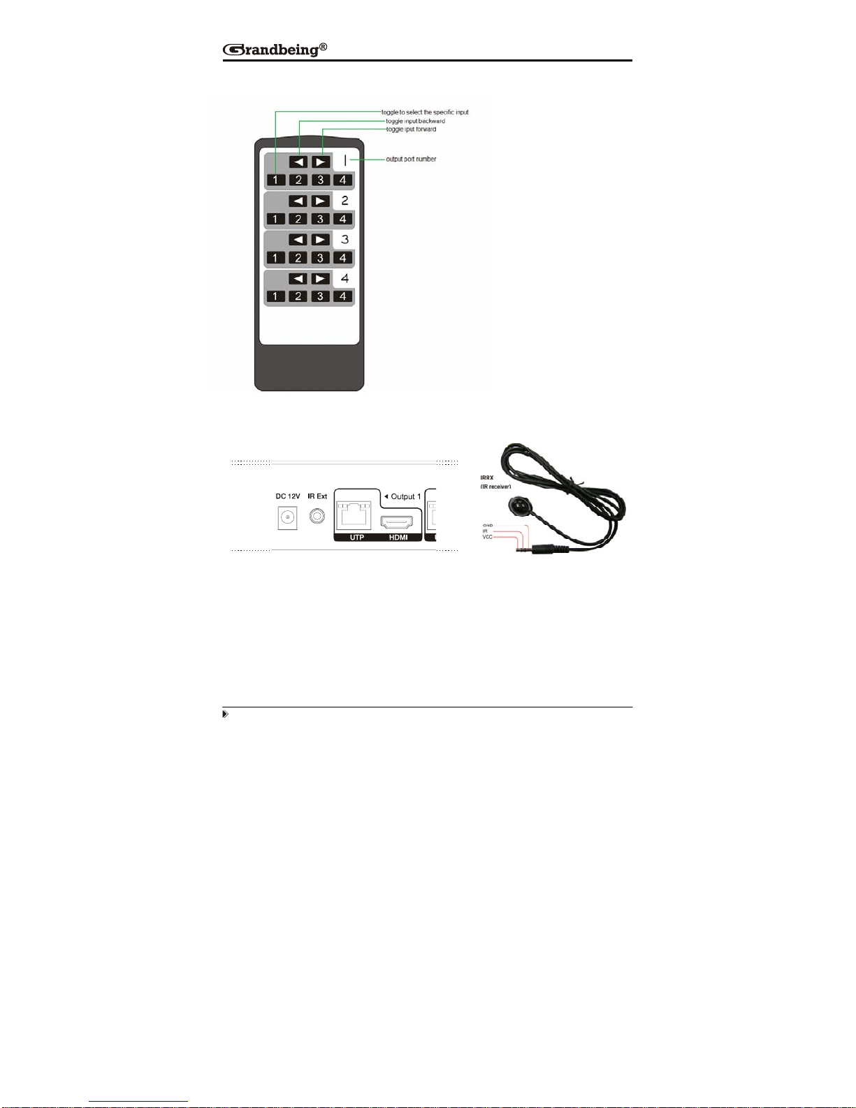
User can control the
HDMI route of the matrix
by using the IR remote.
There are four group key
pads for four output port.
For each output port
source selection, there
are 4 number key and
two arrow key. Press
number key to select
specific input port. Left
arrow is to backward the
input port, and right arrow
to forward in
p
ut
p
ort.
Table of contents


