BEFORE YOU START
•Please ensure that you check all the component parts for quantity and quality before you
commence building the product. Reportany missing parts immediately. The manufacturer will
not accept any responsibility for damaged items once any part of the product has been fitted or
altered in any way.
•Timber is a natural material and will react to varying levels of moisture content - ie. will swell or
shrink. All of the Timber components are pressure treated green. However, should extra
protection be required, they should be treated using a wood preservative treatment, following the
manufacturers instructions.
•It is advisable to drill pilot holes to avoid the risk of the timber splitting when screwing the
components into place.
HEALTH AND SAFETY
DO ensure there is adequate working space when building the Pergola.
Do NOT overstretch when working from the step ladder.
In order to reduce the risk of suffocation please keep all plastic bags and small parts away from children.
•When you are ready to start, make sure you have the right tools to hand, plenty of space and a
clean, dry area for assembly. It is recommended that two people erect the structure.
Thank you for choosing this garden structure from Grange Fencing Ltd. In order
to gain the most benefit from it please read the following instructions carefully.
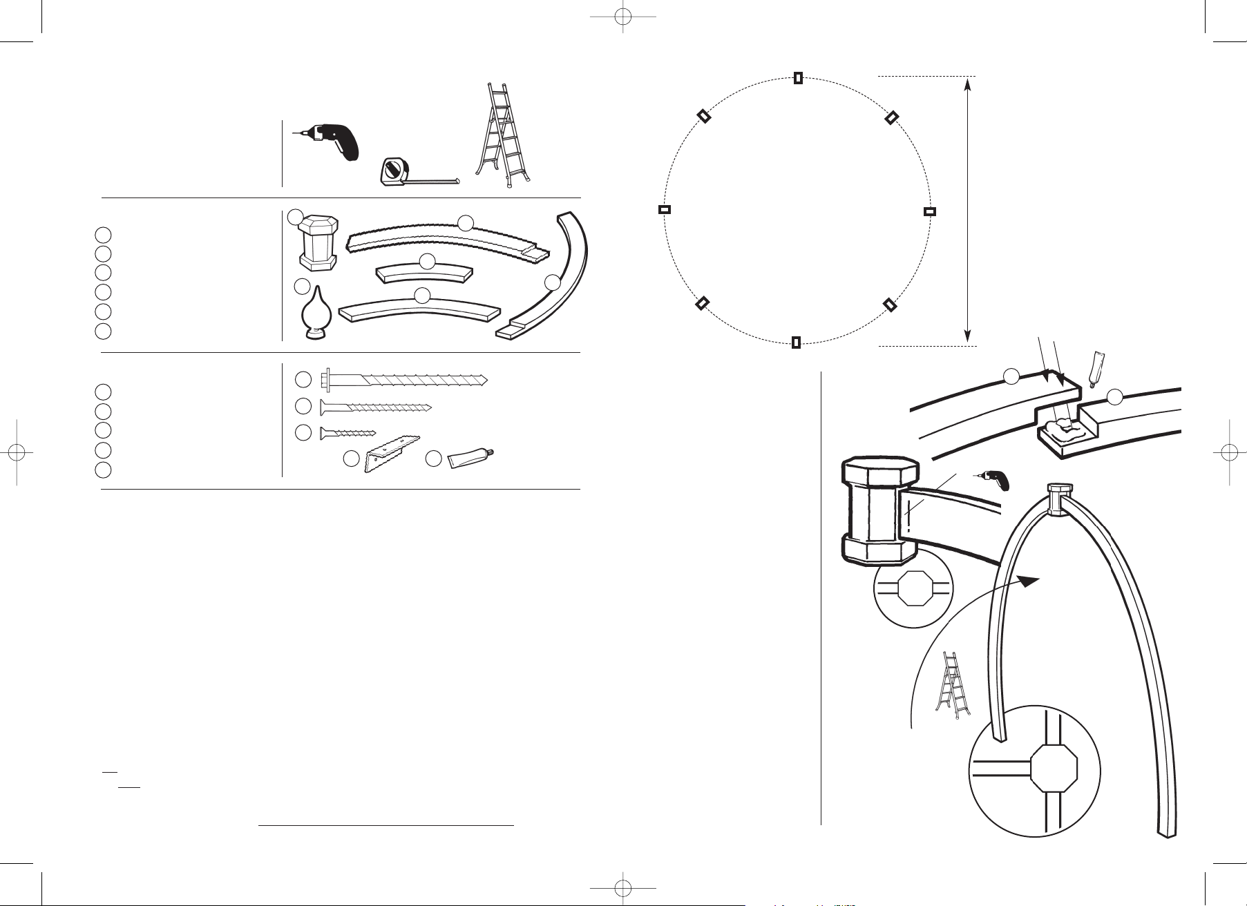
TOOLS REQUIRED (Not Supplied)
POWER DRILL
TAPE MEASURE
STEPLADDER
PARTS LIST
CENTRE BLOCK 1
FINIAL 1
UPPER LEG SECTION 8
LOWER LEG SECTION 8
UPPER LEG BRACE 4
LOWER LEG BRACE 4
HARDWARE PACK
SCREW 150 (6” Index Screw) 8
SCREWS M10 x 4” 32
SCREWS M3.5 x 1.5” 64
RIGHT ANGLE BRACKET 8
WOOD GLUE 8
ASSEMBLY INSTRUCTIONS
STEP 1
Take one of each of the upper
and lower leg sections (3&4).
On a flat surface, fix the sections
together using the glue provided.
Screw together as fig.1 using
screws (C).
Repeat for the remaining seven
leg sections. Make sure the
assemblies arein a flat dryarea.
ALLOW THE GLUE TO SET
OVERNIGHT.
STEP 2
Drill a pilot hole through the top
of the leg section at an angle for
the screw (a)to go through into
the Centre Block (1).
Fix the Leg Section to the Centre
Block as shown in fig.2
STEP 3
Fix a second Leg Section in the
same way directly opposing the
one fitted in Step 2.
STEP 4
Asecond person will be required
to assist at this point; and a step
ladder.
Raise the assembly into an
upright condition. Fix a third leg
assembly at 90˚ to those fitted.
STEP 5
Fix the remaining leg sections to
complete the circle.
(continued overleaf)
1
c
cc
d
e
2
3
4
5
6
a
b
d e
a
c
b
APOLLO
‘FOOTPRINT’
LIFT THE STRUCTURE
INTOAN UPRIGHT
POSITION AND ADD THE
THIRD LEG AT A RIGHT
ANGLE TOTHE FIRST TWO
3.4m
13
2
6
5
4
STEP 1
STEP 2
3
4
STEP 4
a
(fig.2)
(fig.3)
(fig.1)
Apollo Pergola Inst 8/7/11 09:46 Page 2


