2 | P a g e
1. Remove the amp top cover, remove all old tubes then iinstall all new tubes to the right sockets –make sure no tubes were installed in the
wrong socket. This amp has all 8 sockets of same size so do not install wrong type of tubes to any socket! Leave the amp top cover off.
2. Put the amp on its side with a soft cloth under it to avoid scratching the finish. Take off the bottom cover by removing all screws.
3. Turn the amp while it’s on its side to have the bottom of the amp facing you, the front meter on your right hand side. Check again that all
tubes are installed securely at this time.
4. Connect the amp to source signal and speakers, check all connections to make sure they are correct then turn on the amp while it is on its
side, bottom facing you, front meter on your right hand side.
(Caution!!!!! The amp is now live with power, do NOT touch anything inside the amp with bare hands or any object –there is lethal
voltage inside the amp.)
5. Use a multi-meter with settings set to DC 20V, connect the black (negative) probe to the negative speaker post (black). Do not connect to
the red speaker post!!! Leave the speakers connected to the amp at the same time –do not leave the amp on without speaker load at any
time.
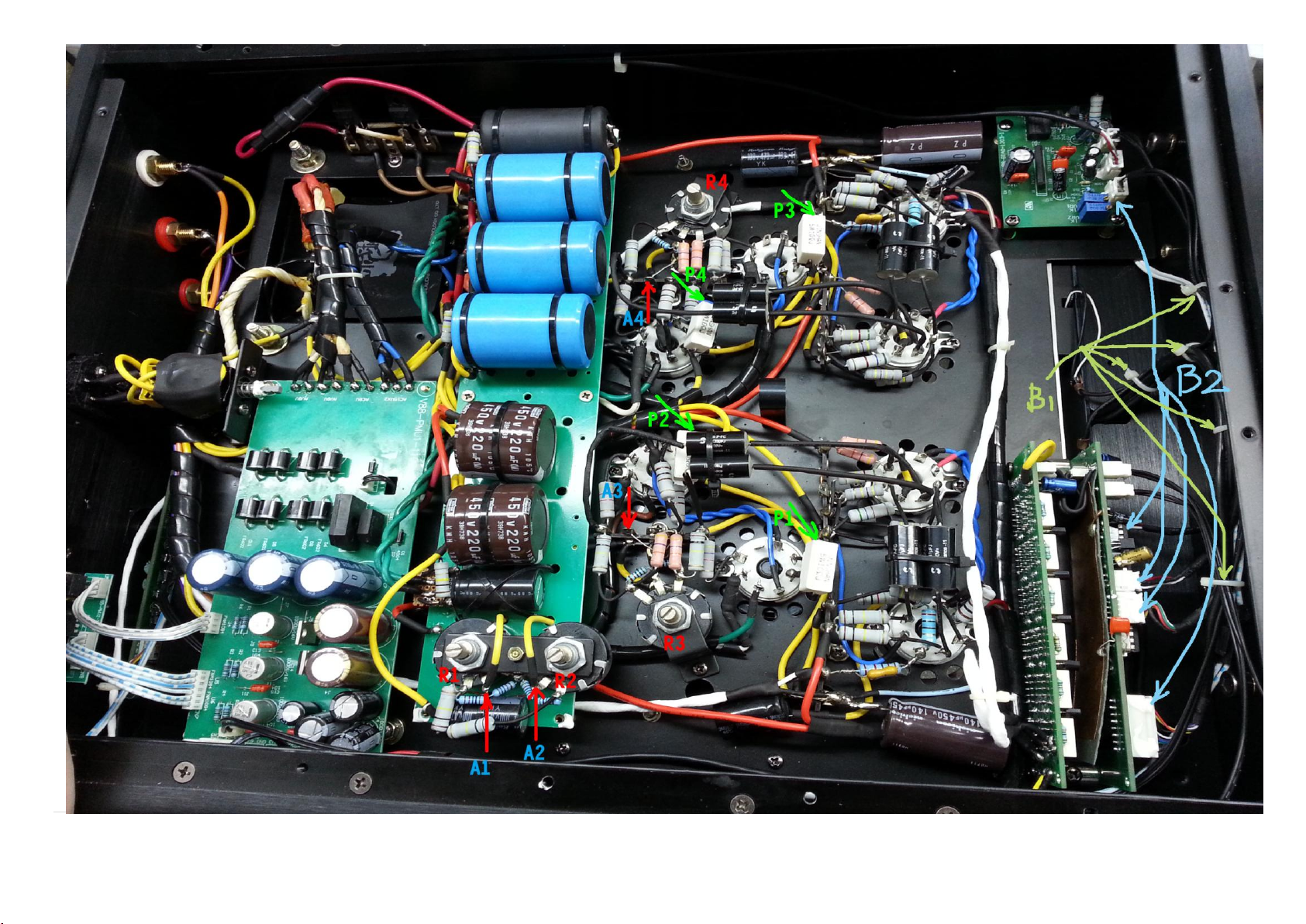
6. Use the multi-meter’s red (positive) probe to test the voltage at P1, P2, P3 and P4. (When you finish the bias process, all 4 spots should
have voltage reading of 0.4V. Keep each reading as close as possible to each other for best results.)
With the red probe at test point P1, use a small screw driver to adjust R1 slowly while reading the voltage meter to 0.4V.
With the red probe at test point P2, use a small screw driver to adjust R1 slowly while reading the voltage meter to 0.4V.
With the red probe at test point P3, use a small screw driver to adjust R2 slowly while reading the voltage meter to 0.4V.
With the red probe at test point P4, use a small screw driver to adjust R2 slowly while reading the voltage meter to 0.4V.
With the red probe at test point P1 again, use a small screw driver to adjust R3 slowly while reading the voltage meter to 0.4V.
With the red probe at test point P2 again, use a small screw driver to adjust R3 slowly while reading the voltage meter to 0.4V.
With the red probe at test point P3 again, use a small screw driver to adjust R4 slowly while reading the voltage meter to 0.4V.
With the red probe at test point P4 again, use a small screw driver to adjust R4 slowly while reading the voltage meter to 0.4V.