manuals.online logo
Brands
  1. Home
  2. •
  3. Brands
  4. •
  5. Neve
  6. •
  7. Amplifier
  8. •
  9. Neve Neve 4081 User manual

Neve Neve 4081 User manual

Other manuals for Neve 4081

3

Other Neve Amplifier manuals

Neve 1073 OPX User manual

Neve

Neve 1073 OPX User manual

Neve 1073DPX User manual

Neve

Neve 1073DPX User manual

Neve 1073 User manual

Neve

Neve 1073 User manual

Neve 1073 OPX User manual

Neve

Neve 1073 OPX User manual

Neve Portico 5032 User manual

Neve

Neve Portico 5032 User manual

Neve Neve 4081 User manual

Neve

Neve Neve 4081 User manual

Neve 1073N User manual

Neve

Neve 1073N User manual

Neve Portico 5012 User manual

Neve

Neve Portico 5012 User manual

Neve 1073 OPX User manual

Neve

Neve 1073 OPX User manual

Neve 1073SPX User manual

Neve

Neve 1073SPX User manual

Neve 1073 User manual

Neve

Neve 1073 User manual

Neve Neve 4081 User manual

Neve

Neve Neve 4081 User manual

Neve Neve 4081 User manual

Neve

Neve Neve 4081 User manual

Popular Amplifier manuals by other brands

ASTRO HVO V40 P operating manual

ASTRO

ASTRO HVO V40 P operating manual

Marantz SUPERSCOPE BLA-545 Service data

Marantz

Marantz SUPERSCOPE BLA-545 Service data

NAD CI980 Quick setup guide

NAD

NAD CI980 Quick setup guide

Technics SE-CH770 Service manual

Technics

Technics SE-CH770 Service manual

Harman Kardon HK6300 instruction manual

Harman Kardon

Harman Kardon HK6300 instruction manual

NAD T975 owner's manual

NAD

NAD T975 owner's manual

McIntosh MA6850 Brochure & specs

McIntosh

McIntosh MA6850 Brochure & specs

Electro-Harmonix ENGLISH MUFF’N manual

Electro-Harmonix

Electro-Harmonix ENGLISH MUFF’N manual

Viatron Autrix Technical manual

Viatron

Viatron Autrix Technical manual

GME GA9800 instruction manual

GME

GME GA9800 instruction manual

Atlas CP700 Specification sheet

Atlas

Atlas CP700 Specification sheet

Roland KC-1000 owner's manual

Roland

Roland KC-1000 owner's manual

Pyle PFMRA350BW user manual

Pyle

Pyle PFMRA350BW user manual

Advantage S-250 manual

Advantage

Advantage S-250 manual

IRT Electronics DVA-3007 manual

IRT Electronics

IRT Electronics DVA-3007 manual

Dimavery BA-100 Series user manual

Dimavery

Dimavery BA-100 Series user manual

Sony XM-S400D operating instructions

Sony

Sony XM-S400D operating instructions

Schertler ROY X quick guide

Schertler

Schertler ROY X quick guide

manuals.online logo
manuals.online logoBrands
  • About & Mission
  • Contact us
  • Privacy Policy
  • Terms and Conditions

Copyright 2025 Manuals.Online. All Rights Reserved.

NEVE
4081
Quad Mic Preamp
User Manual
for
Software V1.02 or later
Issue 2
4081 User Manual Issue 2
Health & Safety Notice
FOR YOUR OWN SAFETY AND THE PROTECTION OF OTHERS,
PLEASE OBSERVE THE FOLLOWING HEALTH AND SAFETY INSTRUCTIONS
[READ THESE INSTRUCTI NS AND KEEP THEM HANDY
[HEED ALL SAFETY WARNINGS
[D N T USE NEAR WATER
[CLEAN NLY WITH A DRY CL TH
[D N T INSTALL NEAR HEAT S URCES
[D N T BL CK VENTILATI N PENINGS
[PR TECT THE P WER C RD
[USE NLY ACCESS RIES SPECIFIED BY THE MANUFACTURER
[UNPLUG WHEN UNUSED F R L NG PERI DS F TIME
[REFER ALL SERVICING T QUALIFIED PERS NNEL NLY
[N USER SERVICEABLE PARTS INSIDE
FAILURE TO FOLLOW THESE PROCEDURES AND RECOMMENDATIONS
COULD INVALIDATE THE MANUFACTURER'S WARRANTY
© ® 2008 AMS Neve Ltd own the copyright of all information and figures contained in this manual which are not to be copied or
reproduced by any means or disclosed in part or whole to any third party without written permission.
As part of our policy of continual product impro ement, we reser e the right to alter specifications without notice but with due regard to
all current legislation.
Disclaimer: The information in this manual has been carefully checked and is belie ed to be accurate at the time of publication.
Howe er, no responsibility is taken by AMS-Ne e for inaccuracies, errors or omissions nor any liability assumed for any loss or damage
resulting either directly or indirectly from use of the information contained within.
Trademarks: All trademarks are the property of their respecti e owners and are hereby acknowledged.
- 2 -
4081 User Manual Issue 2
Table of Contents
Health & Safety Notice.....................................................................................................................................2
Introduction........................................................................................................................................................4
Channel Controls..............................................................................................................................................5
Rear Connectors...............................................................................................................................................6
Installing the soft are – PC............................................................................................................................10
USB Driver.............................................................................................................................10
4081 Software........................................................................................................................11
Standalone Control Setup – PC.....................................................................................................................13
Communications Port..............................................................................................................14
MIDI Port Setup.....................................................................................................................15
Reset Current Rack / Reset All Racks.........................................................................................15
Checkboxes...........................................................................................................................15
Installing the soft are – Mac.........................................................................................................................17
Pro Tools Control Setup...................................................................................................................................19
Technical / Physical Information...................................................................................................................23
Dimensions.......................................................................................................................................................23
Po er Requirements.......................................................................................................................................23
Audio Specification........................................................................................................................................23
Head Office:
AMS Neve
Billington Road
Burnley
Lancashire
England
BB11 5UB
Phone: +44 (0) 1282 457 011
Fax: +44 (0) 1282 417 282
London Office:
+44 (0) 2074 323 858
Email:[email protected]om
Web: www.ams-neve.com
Support: www.ams-neve.info/ftp/
- 3 -
4081 User Manual Issue 2
Introduction
The 4081 Quad Mic Preamp builds on the incredible success of the 1081 and 1081R modules and
provides both powerful control and legendary Neve sound.
Perfect for vocals, ADR and Foley recording, the 4081 features make it the number one choice for any
studio, B truck or live stage environment.
Every function of the 4081 can be controlled directly from the front panel or by remote control using a
Mac or Intel based computer with Neve Remote Control software.
This provides a simple and elegant solution for users of ProTools, Nuendo, Cubase and similar DAW
systems.
Multiple 4081 units can be linked together to create up to 64 independent channels of Mic Preamps or
Line Level inputs, all controlled from a single point.
An optional Digital module provides a Firewire/AES interface with four channels of A/D and D/A
conversion to either AES or Firewire.
An Insert point is available before the A/D converter on each channel to allow external, analogue
outboard equipment to be switched into the signal path.
•Legendary Neve microphone preamp design.
•Four genuine 1081 Mic preamp channels in a single 8.5” wide unit.
•Two units can be fastened together to provide 8-channels in a single 19” unit.
•Remote control using a Mac/Intel computer and the Neve remote control software.
•XLR Mic input can be switched between Mic and electronically balanced Line.
•Switchable 48V Phantom power supply.
•Digital I/ ption:
•Firewire/AES interface with four channels of A/D conversion to either AES or Firewire and 4 channels
of D/A conversion.
•Analogue Insert (pre A/D converter) per channel.
- 4 -
4081 User Manual Issue 2
Channel Controls
The channels can be controlled from the front panel, from a remote Mac or
PC or from Pro Tools using the optional remote control software.
By default, the unit powers-up with all functions locally controllable and
settings are retained on power-down.
The unit is powered by the silver switch with the Neve logo, which will
light red once the power is on.
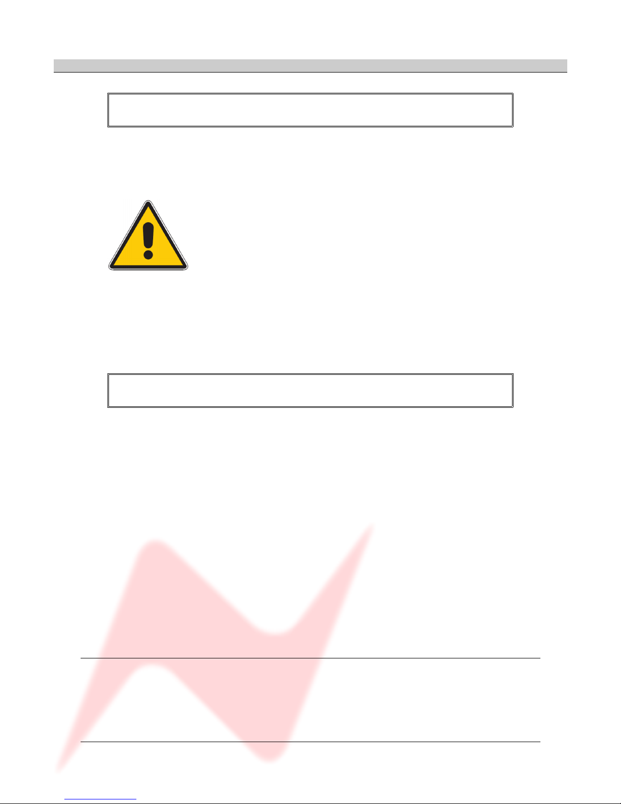
Front panel control is available on each input for:
▪48V: Turns on Phantom Power to the Mic (Not available for LINE)
▪- 0: Pad, attenuates the incoming Mic signal by -20dB (Not available
for LINE)
▪LOW Z: Impedance for Ribbon Microphones (Not available for LINE)
▪MIC/LINE: Selects between the Mic or Line input.
The button lights yellow when MIC is selected; the button will be unlit
for LINE.
▪Ø: Swaps the incoming phase of the Mic or Line signal.
▪INS: This function is controls the source for the A/D in the FireWire
expansion module if fitted.
When illuminated, allows an external Insert Pre- the A/D of the
expansion module.
Turning the Gain control will vary the gain as shown in the display
beneath.
The Gain level is not related to the actual position of the knob, which will
infinitely rotate.
•The MIC gain control runs from +20dB to +70dB in 5dB steps.
•The LINE gain control runs from 0dB to +20dB in 5dB steps.
Just beneath the Gain control are two leds that indicate:
•Signal Presence (lights green at approx -30dBu or greater)
•Signal overload (lights red at 2dB below clipping)
The metering point is Post- the Gain stage.
The maximum signal level is 26dBu.
The Gain knob also has a push-switch which only has a function if the unit
is attached to an AMS Neve 88R console, where it is used to interrogate
console control settings (to be implemented in V2.0 software)
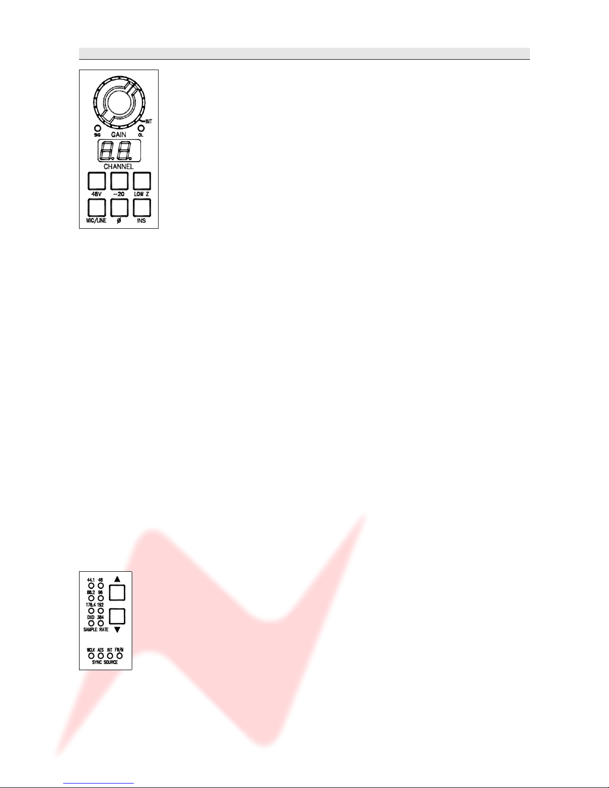
If the optional Digital / Firewire hardware is fitted, the Sample Rate
leds and adjacent buttons will also function.
The unit automatically detects the type and sample rate of the incoming
sync signal if a connection is made to the WCLK I/P connector on the
rear.
The  and  buttons are used to step through the available sample rates
when running on internal sync.
•If running on Internal sync, the WCLK O/P BNC connector on the rear
will transmit this sync.
•If running on an External sync source, the WCLK O/P BNC connector
on the rear will transmit this sync instead.
The leds will reflect the sample rate & sync source once selected.
- 5 -
4081 User Manual Issue 2
Rear Connectors
( ptional Digital Board not shown).
Mic / Line Input XLRs
Employs standard XLR wiring:
1Screen
Hi
3Lo
Mic / Line Output XLRs
These can either be used as Direct utputs from the unit, or as Insert
Sends.
The utput is Post- the Gain control.
Pin-outs as above.
Po er input
48 volts, 8-pin connector.
This connector is polarised so can only be connected in one way.
INS IN / LINE OUT
25-way D-type connector contains the Insert Return signals.
The Line Out part of this connector will have no function unless the
optional AD/DA card is fitted (see below).
USB / RS 485
It is possible to 'daisy-chain' multiple units together so they are controlled
via USB on a Mac or PC.
The first unit on the chain should be connected to the Mac or PC by a USB
cable (not supplied).
The blue USB/RS485 button on the rear of this unit should be pushed in.
Subsequent units are connected from the RS 485 OUT of the 1st unit, to
the IN on the 2nd; from the OUT of the 2nd to the IN of the 3rd and so on
- 6 -
4081 User Manual Issue 2
(these subsequent units should have the blue USB/RS485 button on the
rear pushed out to select RS485 control).
The RS 485 communication protocol uses standard RJ9 connectors for
connecting cables where multiple units can be chained together (cabling
not supplied).
Please note that when connecting multiple units, each 4081 should have a
unique ID as described below.
Cable Specification
The RS-422 specification recommends 24AWG twisted pair cable with a
shunt capacitance of 16 pF per foot and 100 ohm characteristic
impedance.
These recommendations should be used for RS-485 systems as well.
We also recommend using shielded cable.
There are many cables available meeting the recommendations of RS-485
made specifically for this application. Another choice is the same cable
commonly used in the twisted pair Ethernet cabling. This cable, commonly
referred to as Category 5 cable, is defined by the EIA/TIA/ANSI 568
specification.
This cable has a maximum capacitance of 17 pF/ft (14.5 pF typical) and
characteristic impedance of 100 ohms.
Category 5 cable is available as shielded twisted pair (STP) as well as
unshielded twisted pair (UTP) and generally exceeds the recommendations
for RS-422 making it an excellent choice for RS-422 and RS-485 systems.
4081 unit ID dip s itches
When remotely controlling more than one unit, the ID dip-switches on the
rear of the unit need to be set so that each sequentially numbered unit on
the chain responds to the correct commands.
The first 3 switches from left to right are used to set the machine IDs from
1-8. These switches are n when in the down position (the right-most
switch on this block – Switch 4 - puts the unit into 'Bootloader Mode'
where the unit software can be updated via USB, so is therefore not used
to set the unit ID).
Unit ID Switch 1 Switch Switch 3
1ff ff ff
On ff ff
3ff On ff
4 On On ff
5ff ff On
6 On ff On
7ff On On
8 On On On
Where there are more than 8 units on an RS 485 chain, the IDs for units
greater than 8 are set using a dip-switch on the switch-block labelled
SW inside the unit (just next to a programming connector labelled J14
on the middle left of the board).
- 7 -
4081 User Manual Issue 2
For this switch, it is On when in the up position.
>Remove the lid to the unit, and set the 1st (left-most) switch on this
block to be ON, then set the switches on the rear of the unit to the
following:
Unit ID Switch 1 Switch Switch 3
9ff ff ff
10 On ff ff
11 ff On ff
1 On On ff
13 ff ff On
14 On ff On
15 ff On On
16 On On On
If a unit's ID is changed, the power must be switched off and on again for
the remote control software to receive the new ID number.
If the unit IDs are set incorrectly, they will either fail to respond or
multiple units will respond to a single command.
Technical Earth
When switched on, internally connects zero volts to the unit chassis.
- 8 -
This block of switches may
be co ered with a thin
protecti e film, which will
need to be carefully remo ed
before attempting to set the
switches.
4081 User Manual Issue 2
Optional Digital / Fire ire card
This optional module has 2 FireWire ports, Wordclock sync IN and OUT
and a 25-way D-type connector for AES Ins/ uts.
If this option is not present, there will be a blanking plate fitted instead,
(as shown in the previous section), plus the Sample Rate leds & buttons
on the front of the unit will not function.
The AES IN/OUT and Firewire ports are intelligent, in that if a Firewire
connection is detected, then FireWire will be the digital interface.
If a Firewire connection is not detected, the unit will presume the audio is
coming in via the AES IN/OUT 25-way D-type connector.
The expansion module the also has 4 DA/AD converters:
•AES signals going into AES IN/OUT (or Firewire if detected), these
signals will also be output as analogue from LINE OUT of the 25 way
D-sub connector.
•If INS is selected on a channel, the corresponding analogue input
signal connected to INS IN of the 25 way D-sub connector, will be
converted and output as AES signals from the AES IN/OUT (or
Firewire if detected).
By default, the Post- gain amplified signal from the Mic/Line input will be
routed to the A/D inputs.
- 9 -
4081 User Manual Issue 2
Installing the soft are – PC
USB Driver
Before continuing, please connect the 4081 by USB to the PC and power
the unit up.
Before installing the control software, you will need to install a USB driver
to enable communication between the PC and the 4081.
This can be downloaded from:
http://www.ams-neve.info/ftp/4081_USB_Driver.exe
When presented with the option to either Run or Save, click Save and
specify a location for the file to be saved to.
This is an executable file, so once it has downloaded, double click to run
and install it.
The Windows operating system will be determined, as will the correct
driver for your system.
A Windows CMD screen will show the install by a series of progressing
dots.
As the driver nears the end of it's installation procedure, the CMD screen
will close and the Taskbar will show two messages:
The first will show that the driver has found new hardware and a USB port
has been detected.
The second will show that it is ready to use.
You can now install the 4081 control software.
- 10 -