These supplementary Instructions must be read in
conjunction with the Vortex boiler Installation Instructions
supplied with the boiler.
Both the Vortex boiler Installation Instructions and these
Supplementary Instructions must be lef t with the User on
completion of Installation and Commissioning.
NOTE
!
2.1 Update to Main Installation Instructions
These Supplementary Instructions are designed to cover the
differences between the Grant Vortex and the new Grant VortexBlue
low NOx boilers, as much of the installation, commissioning,
servicing and operation is identical to the standard Vortex boilers.
The following sections of the Vortex Installation Instructions
(supplied with the boiler) have not been changed and should be
referred to during the installation and commissioning of this boiler:
• Section 3 Oil Supply and Storage
• Section 5 Pipe Connections
• Section 6 Condensate Disposal
• Section 7 Sealed Systems
Refer to Section 2.6 of these instructions
• Section 9 Flues and Air Supply
• Section 14 Health and Safety Information
• Section 16 Guarantee
2.2 General
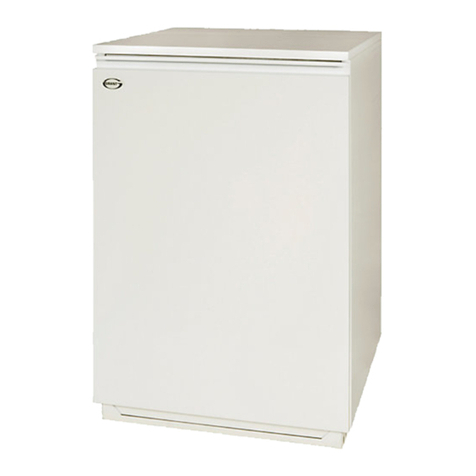
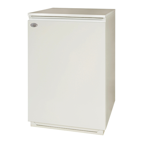
The new Grant VortexBlue range of high efficiency low NOx oil fired
boilers consists of 15 models including Internal, Internal System
and External Modules as well as both Internal and External Combi
boilers.
All models are available in three outputs – 21kW, 26kW and 36kW.
The Internal, Internal System and External Modules are supplied
factory set at the ma ximum outputs of 21kW, 26kW and 36kW but
can be de-rated to a lower output on commissioning if required.
Refer to Section 3.3 of these Supplementary Instructions for a full list
of all models and outputs.
2.3 Low NOx Technology
Grant VortexBlue boilers are designed to meet both the forthcoming
European Ecodesign (ErP) emissions limits due to be introduced in
September 2018, and to maintain the high efficiencies expected of
Grant Vortex oil fired boilers.
They combine the proven Grant condensing boiler technology with
the Riello RDB BLU compact low NOx blue flame burners.
Grant VortexBlue boilers can be used with all the Grant flue system
options available for the standard Vortex boilers. Refer to the
Installation Instructions supplied with the boiler for details.
2 Introduction
2.4 Boiler Controls
2.4.1 Combi Boilers
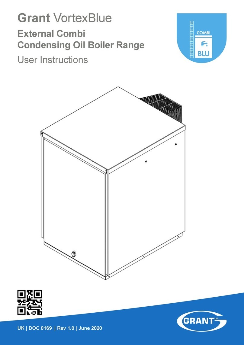
The Grant VortexBlue Combi boilers (internal and external) have
the same electronic control system as fitted to the standard Vortex
Combi models.
All wiring details for external controls (programmers, room
thermostats, etc.) are given in Section 8 of the Vortex Combi
Installation Instructions provided with the boiler.
2.4.2 Internal boilers and External Modules
The Grant VortexBlue Internal boilers and External Modules
incorporate a new electronic control system based on the one used
in the Grant Vortex Pro Combi boilers.
This uses an electronic boiler thermostat and has LED lights to
indicate the operating status of the boiler. For details on how to
operate the boiler please refer to Section 1.
Refer to Section 5 of these Supplementary Instructions for further
details and electrical connection diagrams.
A service switch is fit ted to the control panel of the external
modules to allow the service engineer to test-fire the boiler.
When set to 'ON' the switch temporarily by-passes the
external control system to operate the boiler.
This is a 'momentary' or non-latching switch that cannot be
left set to 'ON'. The boiler will automatically revert to normal
operation when 15 minutes have elapsed since it was last
operated.
If required, this 15 minute override period can be stopped by
switching the boiler ON/OFF switch 'OFF' and then back to
'ON'.
The boiler will then operate as normal under control of the
external heating/hot water controls (timer, room thermostat
or programmer).
NOTE
!
2.5 Fuel Type
All VortexBlue boilers are designed for use with Kerosene (Class C2)
only.
The use of any other fuel, e.g. Gas Oil (Class D), is not permitted
with any of the VortexBlue boilers and may invalidate the product
guarantee.
2.6 Sealed Systems
The following sealed system kits are available for the external
modules:
VortexBlue External Grant UK product code
VTXBFOM21
VTXOMSSKIT26
VTXBFOM26
VTXBFOM36 VTXOMSSKIT46
Section 2: IntroductionPage 06
