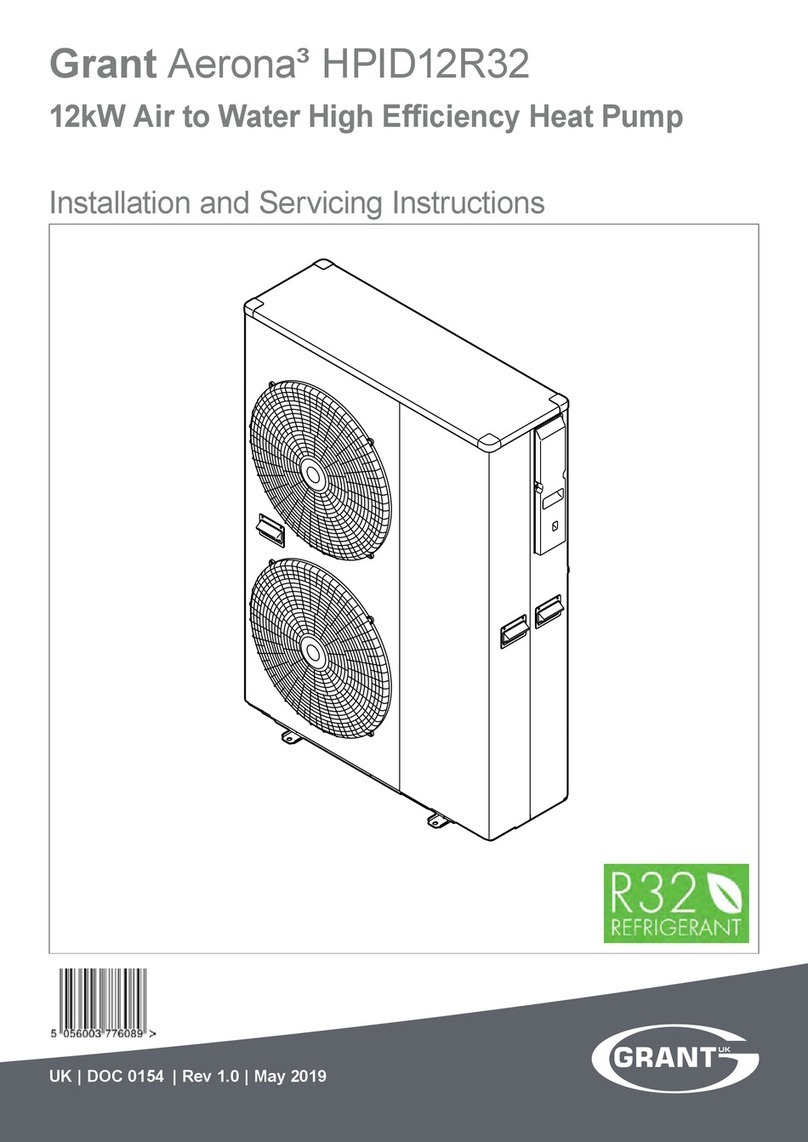
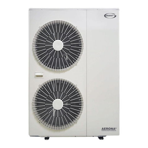
Grant Aerona3 Series User guide

Grant Aerona³
Air to Water High Efficiency
Heat Pump Range
Installation and Servicing Instructions
R32
IRL| DOC 0017| REV 00.00| FEBRUARY 2021

IMPORTANT NOTE FOR INSTALLERS
These instructions are intended to guide installers on the installation,
commissioning and servicing of the Grant Aerona³ heat pump. After
installing the heat pump, leave these instructions with the user.
A user handbook is available to guide users in the operation of the heat
pump.
SPECIAL TEXT FORMATS
The following special text formats are used in these instructions for the
purposes listed below:
PRODUCT CODES COVERED
These instructions cover the following product codes:
Product code
HPID6R32 - 6kW
HPID10R32 - 10kW
HPID13R32- 13kW
HPID17R32- 17kW
Output at 7°C air and 35°C flow temperature
SERVICING
The heat pump should be serviced at least every twelve months and the
details entered in the Service Log in the user handbook.
WARNING
Warning of possible human injury as a
consequence of not following the instructions
in the warning.
Caution concerning likely damage to
equipment or tools as a consequence of not
following the instructions in the caution.
Used for emphasis or information not directly
concerned with the surrounding text but of
importance to the reader.
CAUTION
NOTE
IMPORTANT NOTE FOR
INSTALLERS
The data label gives you very important
information about the installed heat pump.
Do not remove this label from the heat
pump under any circumstances. The year of
manufacture is contained within the serial
number (SN). The last two digits of the
middle
set of four numbers (eg. 8820) indicates the
year of manufacture.
In this example, the year is 2020
Power Quality Information
HPID6R32 Complies with the Technical requirements of BS EN/IEC 61000-3-2
Complies with the Technical requirements of BS EN/IEC 61000-3-3
HPID10R32 Complies with BS EN/IEC 61000-3-11 & BS EN/IEC 61000-3-12
Complies with the technical requirements of BS EN/IEC 61000-3-2
Complies with the technical requirements of BS EN/IEC 61000-3-3
HPID13R32 Complies with BS EN/IEC 61000-3-11 & BS EN/IEC 61000-3-12
HPID17R32 Complies with BS EN/IEC 61000-3-11 & BS EN/IEC 61000-3-12
8820
This manual is accurate at the date of printing but will be superseded and should be disregarded if specifications and/or appearances are changed in the interests of continued product improvement. However, no respon-
sibility of any kind for any injury, death, loss, damage or delay however caused resulting from the use of this manual can be accepted by Grant Engineering (Ireland) ULC, the author or others involved in its publication.
All good sold are subject to our official Conditions of Sale, a copy of which may be obtained on application.
© Grant Engineering (Ireland) ULC No part of this manual may be reproduced by any means without prior written consent.
GRANT ENGINEERING (IRELAND) ULC
Crinkle, Birr, Co Offaly
R42 D788, Ireland
www.grantengineering.ie
Tel:+353 (0)57 91 20089 Fax: +353 (0)57 91 21060

1 Introduction 4
1.1 General 4
1.2 Main Components 4
1.3 Planning Permission 4
1.4 Important Advice 4
1.5 Product Contents 4
1.6 Installation Accessories 4
1.7 Control Parameters 4
1.8 Heat Pump Components 4
2 Technical Data 6
2.1 Heat Pump Technical Data 6
2.2 Main Supply Cable 6
2.3 Base Tray Heater 6
2.4 Heat Pump Dimensions 7
2.5 Remote Controller Dimensions 8
3 Installation Information 9
3.1 Introduction 9
3.2 Heating System Design Criteria 9
3.3 Regulations 10
3.4 Heat Pump Location 10
3.5 Preparation for Installation 10
3.6 Installing the Heat Pump 11
3.7 Metering for Domestic RHI Installations 12
3.8 Volumiser Tanks 12
3.9 Hydraulic Diagram 13
3.10 Before you Commission 14
3.11 Completion 15
3.12 Installation Checklist 16
4 Sealed Systems 18
4.1 Sealed System Requirements 18
4.2 Filling the Sealed System 19
4.3 Pressure Relief (Safety) Valve Operation 19
5 Domestic Hot Water 20
5.1 Temperature Control 20
5.2 Heat Pump Cylinders 20
5.3 Legionella 21
5.4 Automatic DHW Boost Kit 21
6 Electrical 24
6.1 Main PCP 24
6.2 Terminal PCB Input/Output 25
6.3 Power Supply 25
6.4 Wiring first fix Options 26
6.5 Tightening Torques 27
6.6 Solar Thermal 27
6.7 Connection of Heating System Control 28
6.8 Connection of Display pad 28
6.9 Installation of Heatpump and
Preplumbed Cylinder 28
6.10 First fix wiring options 29
6.11 Second fix wiring 30
7 Display Pad 32
7.1 Display Pad 32
7.2 Installation Requirements 32
7.3 Installing the Display Pad 32
7.4 Connecting the Display Pad 33
to the Heat Pump
7.5 Buttons 34
7.6 Display Panel 35
8 Operation 36
8.1 Heat Pump Operation 36
8.2 Weather Compensation 38
8.3 Water Pump Management 39
8.4 Frost Protection 42
8.5 ON/OFF DHW Production Remote Contact 44
8.6 ON/OFF Heating Remote Contact 45
8.7 Night Mode 46
8.8 Low Tariff 47
9 Commissioning 48
9.1 System Setup 48
9.2 Setting the Day and Time 48
9.3 Access for Parameter Settings 49
9.4 Accessing the Parameter Setting Menu 49
(User level)
9.5 Accessing the Parameter Setting Menu 49
(Installer level)
9.6 Temperature Control - DHW function 49
9.7 Parameters Input/Output 50
9.8 Remote Controller Back Light Display 50
Parameters
9.9 Weather Compensation 51
9.10 Frost Protection Function Setting 51
9.11 Pump Operation and Air Bleeding 51
from Heating System
9.12 Pump Output Setting 51
9.13 Coastal Installations 51
10 Servicing 52
10.1 General 52
10.2 Air Inlet and Outlet 52
10.3 Condensate Disposal 52
10.4 Heating System Connections 52
10.5 Heat Pump Controls 52
10.6 Refrigerant 52
10.7 Monitor Display Function 53
11 Fault Finding 54
11.1 Error Code Display 54
11.2 Error History Display 54
11.3 Reset Error Code Display 54
11.4 Error Codes 55
11.5 Table of Controller PCB and Terminal 58
PCB Alarms
11.6 Error Codes and PCB Alarm Figures 59
and Tables
12 Spare Parts 62
12.1 Exploded Diagram - HPID6R32 62
12.2 Spare Parts List - HPID6R32 63
12.3 Exploded Diagram - HPID10R32 64
12.4 Spare Parts List - HPID10R32 65
12.5 Exploded Diagram - HPID13R32 66
12.6 Spare Parts List - HPID13R32 67
12.7 Exploded Diagram - HPID17R32 68
12.8 Spare Parts LIst - HPID17R32 69
13 Declaration of Conformity 68
14 Health and Safety Information 69
14.1 General 69
14.2 Refrigerant (R32) 69
15 Disposal and Recycling 69
16 Product Fiches 70
17 Guarantee 76
Appendix A - Parameters List 78
Appendix B - Wiring Diagrams 80
Appendix C - Parameters 82
Record
Contents Page 3
CONTENTS

Section 1: IntroductionPage 4
1.1 General
The Grant Aerona³ range consists of four compact, MCS approved,
monobloc, air-to-water, inverter driven, single-phase air source heat pumps
working with R32 refrigerant.
It is important that these installation and servicing instructions are followed to
ensure correct installation and operation. Failure to do so may result in poor
performance.
It is not within the scope of this manual to design the heating system or provide
any advice regarding the layout of the system or any of the controls required
for any individual heating system.
These instructions do not replace the installation or users manuals for any
additional components used in the design of your system e.g. cylinders,
motorised valves, programmers, solar thermal devices, buffers, etc.
These instructions must be left with the product for future
reference.
1.2 Main Components
Each model incorporates the following main components:
• DC inverter - this responds rapidly to changing conditions to provide
the necessary output to meet heating demands by varying the speed
and output of the compressor, fan and circulating pump. This reduces the
on/off times of the compressor, keeping the water temperature constant
during operation reducing the electricity consumption.
• Compressor - a high-efficiency DC twin-rotary compressor to provide
smooth performance and quiet operation.
• Plate heat exchanger (condenser) - the high-efficiency plate heat
exchanger is used to transfer heat to the heating system primary circuit.
• Fan - a high-efficiency DC fan motor is used for smooth and quiet
operation. A single fan is fitted to the 6kW (5 blade) and 10kW (3
blade) units. Two fans (3 blade) are fitted to the 13 & 17kW unit.
• Circulating pump - high-efficiency DC pump speed controlled from
the ASHP control PCB.
• Base tray heater - factory fitted electric heater prevents condensate
in the base of the heat pump from freezing. When the ambient
temperature reaches 2.5°C, the base tray heater turns on and at 5.5°C
turns off (ΔT of 3k). This cannot be adjusted or turned off. Refer to
Section 2.3.
• Pressure relief valve - a 3 bar pressure relief valve is factory fitted.
• Air purge valve (automatic air vent) - factory fitted to assist in the
removal of air from the heating primary circuit of the heat pump.
1.3 Planning Permission
The installation of a Grant Aerona³ heat pump on domestic premises may
be considered to be permitted development, not needing an application
for planning permission, provided ALL the limits and conditions listed on the
Planning Portal website are met.
For further information contact your local planning department.
1. 4 Important Advice
1. It is essential that the full layout of the system is understood before the
installation of any component is undertaken. If you are in any doubt,
please stop and seek advice from a qualified heating engineer or from
Grant IRL. Please note that Grant IRL will not be able to offer specific
advice about your system unless we designed it. In this case, we will
always refer you to seek the advice of a qualified system designer.
2. The heat pump must be installed and commissioned in accordance with
these installation and servicing instructions. Deviations of any kind will
invalidate the guarantee and may cause an unsafe situation to occur.
Please seek advice from Grant IRL if any of these user, installation and
servicing instructions cannot be followed for whatever reason.
3. The heat pump contains high pressures and high temperatures during
normal working conditions. Care must be taken when accessing the
internal workings of the heat pump.
4. The heat pump contains an electrically driven fan which rotates at high
speed. Disconnect the heat pump from the electrical supply before
removing the top cover.
1.5 Product Contents
The Aerona³ comes supplied on a single pallet. The following items are
included:
1.6 Installation Accessories
The following are available from Grant IRL:
Product code Description
HPIDFOOT/KIT2 Anti-vibration mounts (2 x 600mm and fixing kit)
HPIDINSU/KIT Through wall insulation kit (22 - 28mm flexible hoses)
1.7 Control Parameters
All parameters are listed sequentially in Appendix A.
1 INTRODUCTION
HPID6R32 HPID10R32 HPID13R32 HPID17R32
Aerona³ heat pump 6kW 1
Aerona³ heat pump 10kW 1
Aerona³ heat pump 13kW 1
Aerona³ heat pump 17kW 1
Condensate drain elbow 1 1 1 1
Anti-vibration shoes 4
¾” BSP x 22 mm flexible
hose c/w washer 2
1” BSP x 28 mm flexible
hose c/w washer 2 2 2
1” nipple 2 2
1” x 1¼” reducing socket 0 0 2 2
22 mm isolating valve 2
28 mm isolating valve 2 2 2
Remote controller 1 1 1 1
Remote controller cable
(length: 8 metres) 1 1 1 1
Installation and servicing
instructions 1 1 1 1
User instructions 1 1 1 1

Section 1: Introduction Page 5
1.8 Heat Pump Components
Air inlet is located in the left and rear of the unit
Air Outlet
Wiring cover
Screw
Air inlet is located in the left and rear of the unit
Air outlet
Wiring cover
Screw
Terminal PCB
Auto-air vent
Terminal block
Pump
Compressor
Pressure relief valve
Main PCB
Main PCB
Terminal PCB
Terminal block
Pump
Pressure relief valve
Auto-air vent
Compressor
Terminal PCB
Pressure relief valve
Auto-air vent
Terminal block
Pump
Compressor
Main PCB
Figure 1-1: Main components (external) - 6kW
Figure 1-2: Main components (external) - 10kW
Figure 1-3: Main components (external) - 13kW & 17kW Figure 1-6: Main components (internal) - 13 kW & 17kW
Figure 1-5: Main components (internal) - 10kW
Figure 1-4: Main components (internal) - 6kW
Air outlet
Wiring lid
Screw
Wiring cover

Section 2: Technical DataPage 6
2.3 Base Tray Heater
The factory fitted electric heater prevents condensate in the base of the heat
pump from freezing. When the ambient temperature reaches 2.5°C, the base
tray heater turns on and at 5.5°C turns off (ΔT of 3k). This cannot be adjusted
or turned off.
Base tray heater specification
V 230V
P185 W
t 110°C
A 0.8A
Resistive load
R 290 Ω
2 TECHNICAL DATA
Technical data
.1 13.6 18.0
.5 11.4 15.3
30 3.47 3.72 3.56
Power supply
93 .76
34 .86
Mechanical protection
Compressor DC twin rotary - inverter driven
1.4aPM)mumixam(erusserP
Refrigerant R32
2151601daehmpmupgnitalucriC
--- -
--- -
--- -
--- -
5151015nim/sertil)muminim(etarwolF
20.22 32.16 40.68 50.88
11.34 19.26 40.62 27.90
)rab3ot1(3.0ot1.0)rab(aPM)metsys(erusserpretaW
6.168.06462.56)A(Bd)lanretxe(ertem1talevelrewopdnuoS
50.6
0.20.28.18.1sertiltnetnocretaW
will be
3.76
4.86
A+++
A+++
2.2 Mains Supply Cable
Always assume maximum possible load when considering
cable sizing.
The cable supplying power from the consumer unit to the heat pump must be
connected via an external 2 pole isolator. This allows the service engineer to
isolate the power supply before working on the heat pump safely.
Refer to Section 6 for connection details.
Table 2-2: Electrical installation requirements
Heat pump
model
Maximum
running current
(A)
MCB
Rating (A) Type
HPID6R32 11 . 2 16 C
HPID10R32 17. 5 20 C
HPID13R32 23.0 32 C
HPID17R32 25.3 32 C

Section 2: Technical Data Page 7
2.4 Heat Pump Dimensions
86616
850 21
R1(25A)
R1(25A)
25 330 38
480173
155540155
7570
357
Circulating water
return port
Circulating water
flow port
680185
36
356
13 330 13
80 80
241000
1418
205590205
Circulating water
flow port
Circulating water
return port
R1 1/4(32A)
R1 1/4(32A)
Figure 2-5: HPID13R32 & HPID17R32 dimensions
Figure 2-4: HPID10R32 dimensions
Figure 2-3: HPID6R32 dimensions
327
57
3885 4
R3/4(20A)
30037.44 2
825 73
675
580
5.2215.221
43
Circulating water
return port
Circulating water
outgoing port
flow port
37.4 300 42
54

Section 2: Technical DataPage 8
2.5 Remote Controller Dimensions
12
37 37
23 23
18.25
120 16.5
6-4.2×7
120
83.5 18.25
(116)
Knock out hole
Mounting plate Door closed Door open
Figure 2-6: Remote controller dimensions

Section 3: Installation Information Page 9
3.2.1 System Design Criteria
A typical condensing oil or gas fired boiler operates with a flow of 70°C and
a return of 50°C, i.e. with a DT of 20°C. A heat pump operates with a flow of
between 30°C and 55°C with a DT of 8°C.
The design of any system in Ireland and the UK is typically based on the
following parameters:
1. That the outside design air temperature can fall to -3°C or lower
2. The internal design temperature can be between 18-22°C depending
on the room concerned.
3. The heat pump operates at lower water temperatures than an oil or gas
fired appliance.
Designing a new system for use with a heat pump is straight forward,
assuming the insulation properties of the dwelling meets or exceeds
current Building Regulations and the lower flow/return temperatures
are taken into account in the selection of the type and size of the heat
emitters used.
While underfloor heating is the preferred heat emitter, a combination of
underfloor heating and radiators, or radiators only, works just as efficiently. It
is necessary, however, to calculate the size of radiator required accurately – if
this is not done, the house will fail to reach the target temperature and will be
costly to rectify after the installation is complete.
When tested to BS EN 14511, the heat output for an heat pump is declared at
the test conditions of 7°C outside air temperature and 35°C or 55°C water
flow temperature.
At all other values of outside air temperature and water flow temperature the
actual heat pump output will vary, e.g. the heat output will:
• decrease with lower outside air temperatures and increase with higher
outside air temperatures at any given water flow temperature, and
• decrease with higher water flow temperatures and increase with lower
water flow temperatures at any given outside air temperature
A back-up boiler can be added to the rated output of the heat pump.
Provided that the heat pump is sized correctly for the system, this back-up
heater will only compensate for any short fall in meeting the heat load for the
property below the minimum design air temperatures.
3.2.2 Heat Emitter Sizing
For guidance on sizing heat emitters, e.g. radiators and/or underfloor
heating, refer to SR50: 2010 code of practice for building services part 1
domestic plumbing and heating.
3.1 Introduction
For the heat pump to operate satisfactorily, install it as outlined in this
installation manual.
• The Grant Aerona³ heat pump should only be installed by a competent
person.
• Before installing the heat pump, please read the following installation
information carefully and install the heat pump as instructed.
• Be sure to follow the safety notices given.
• After completing the installation, check the product operates correctly.
Then, explain to the user about the operation and maintenance
requirements as shown in this manual.
• Be sure to install the heat pump in a suitable location that can support
the heat pump when filled. Installation in an unsuitable location may
cause injury to persons and damage to the heat pump.
• Do not install in a position where there is any possibility of flammable
gas leakage such as from LPG cylinder around the heat pump. Leaked
flammable gas around the heat pump may cause a fire.
• If the leaked refrigerant is exposed to fire, poisonous gas may be
produced.
• Connect the heat pump with the flexible hoses and valves supplied, as
described in this installation manual.
• Do not use an extension cable.
• Do not turn on the power until all installation work is complete.
• Only use correct Grant IRL parts and accessories to avoid accidents
such as electric shock, fire and leakage of water.
• Never touch electrical components immediately after the power supply
has been turned off as electrical shock may occur. After turning off the
power, always wait five or more minutes before touching electrical
components.
• Be sure to connect the power supply cable correctly to the terminal block
as overheating can cause a fire.
• Ensure the wiring lid is fitted following installation to avoid electric shock
at the terminal block.
• Always connect the earth wire to the heat pump.
• Install a correctly rated circuit breaker.
• After installation, the heat pump and heating system must be
commissioned. Hand over all documentation to the end-user and
explain the operating functions and maintenance according to these
instructions.
3.2 Heating System Design Criteria
Before continuing with the installation of the Aerona³ heat pump, please
spend a few minutes confirming the suitability of the heat pump to your system.
Failure to do so may result in poor performance and wasted time:
• Has a room-by-room heat loss calculation been carried out?
• Is this system designed for mono or bivalent?
• If monovalent, total heating capacity?
• If bivalent, what is the load capacity of the heat pump?
• If bivalent, what is/are additional heat source(s)?
• Type of system design? - S-plan, S-plan plus
• Will a buffer be used?
• If yes, what is the capacity of the buffer?
• Has cavity wall insulation been installed?
• Has loft insulation of 300mm been installed?
• Have all system pipes been lagged correctly?
• Are the existing controls being upgraded?
3INSTALLATION INFORMATION
Grant Aerona³ heat pumps should be stored
and transported in an upright position. If not,
then the heat pump MUST be positioned in an
upright position for at least four hours before
being operated.
NOTE

Section 3: Installation InformationPage 10
3.3 Regulations
Installation of a Grant Aerona³ heat pump must be in accordance with the
following recommendations:
• National Building Regulations, e.g. Approved Document G
• Technical Guidance Document L- Conservation of fuel and Energy-
Dwellings (2019)
• SR 50-1: Code of practice for building services- Part 1- Domestic
plumbing and heating.
• Local Bylaws (check with the Local Authority for the area)
• Water Supply (Water Fittings) Regulations 1999
• MCS Installer Standards (if applying for the Renewable Heat Incentive)
• MIS 3005 (Requirements for contractors undertaking the supply,
design, installation, set to work commissioning and handover of
microgeneration heat pump systems)
• MCS 020 (MCS Planning Standards)
• MCS 021 (MCS Heat Emitter Guide for Domestic Heat Pumps)
The installation should also be in accordance with the latest edition of the
following standards and codes of Practice:
• BS 7671 and Amendments
• BS EN 12831
3.4 Heat Pump Location
3.4.1 Selection of position
• Consider a place where the noise and the air discharged will not affect
neighbours.
• Consider a position protected from the wind.
• Consider an area that reflects the minimum spaces recommended.
• Consider a place that does not obstruct the access to doors or paths.
• The surfaces of the floor must be solid enough to support the weight of
the heat pump and minimise the transmission of noise and vibration.
• Take preventive measures so that children cannot reach the unit.
• Install the heat pump in a place where it will not be inclined more than
5°.
• When installing the heat pump where it may exposed to strong wind,
brace it securely.
• If the Aerona³ heat pump is to be installed within 1km of the coast, avoid
siting facing the sea.
• If the Aerona³ heat pump is to be installed within 10km of the coast, the
evaporator must be sprayed with AFC50 and this must be repeated on
each annual service.
• For heat pumps fitted within 5km of the coast, Grant recommend the
unit is pretreated with Blygold, which is done during the manufacturing
process.
Decide the mounting position as follows:
1. Install the heat pump in a location which can withstand the weight of the
heat pump and vibration. Please make sure it is installed level.
2. Provide the indicated space to ensure good airflow.
3. Do not install the heat pump near a source of heat, steam, or flammable
gas.
4. During heating operation, condensate water flows from the heat pump.
Therefore, install the heat pump in a place where the condensate water
flow will not be obstructed.
5. Do not install the heat pump where strong wind blows directly onto the
heat pump or where it is very dusty.
6. Do not install the heat pump where people pass frequently.
7. Install the heat pump in a place where it will be free from adverse
weather conditions as much as possible.
3.4.2 Noise Level
All heat pumps make a noise. Discuss the potential nuisance factor with the
end-user when considering the final position of the heat pump. Take opening
windows and doors into account. It is not essential for the heat pump to be
positioned next to a wall of the house. Behind an out-building may be more
suitable so discuss the options with the end-user.
3.4.3 Orientation
The North face of the building will usually have colder ambient air than any
other side. To ensure maximum efficiency from the Grant Aerona³ heat pump,
position the heat pump on a warmer side. In order of preference, site the heat
pump on a South face followed by either South East or South West, then by
East or West. Only install on a North face if there is no other alternative.
3.5 Preparation for Installation
3.5.1 Base
The heat pump should be installed on a flat trowelled finished concrete base
150mm thick. This base should extend at least 150mm beyond the heat pump
on three sides.
To avoid bridging the DPC, leave a gap of at approximately 150mm between
the concrete base and the wall of the house.
The heat pump must be raised up from the base by approximately 100mm on
suitable anti vibration mounts or blocks.
3.5.2 Clearances
The following minimum clearances must be used to enable the product to be
easily commissioned, serviced and maintained and allow adequate air flow
in and out of the heat pump.
Refer to Table 3-1 and Figure 3-2.
Table 3-1: Clearances
Aspect Minimum clearance required (mm)
Top 300
Bottom Approximately 100*
Front 600
Rear 300
Left 100
Right 600
* Height of A/V mounts (product code: HPIDFOOT/KIT)
00
3
r
evO
mm
Ov
e
r
6
00
mm
Ov
e
r
1
00
mm
Over 300 mm
Ov
e
r
6
0
0
mm
Figure 3-2: Clearances
HPID6R32

Section 3: Installation Information Page 11
Condensate outlet
Figure 3-4: Condensate outlet
3.5.4 Vibration
If the vibration from the heat pump is likely to cause a nuisance, use the
anti-vibration mounts (product code: HPIDFOOT/KIT) and fix the heat pump
securely to the mounts.
3.6 Installing the Heat Pump
3.6.1 Insulation
The complete water circuit, including all pipework, must be insulated to
prevent heat loss reducing the efficiency of the heat pump and also to prevent
damage due to frozen pipes.
3.6.2 Connecting the Heating System to the Heat Pump
• Water connections must be made in accordance with diagram in this
manual and the labels on the heat pump.
• Be careful not to deform the heat pump pipework by using excessive
force when connecting.
• Pipework should be flushed before connecting the heat pump.
• Hold the pipe end downwards when removing burrs.
• Cover the pipe end when inserting it through a wall so that no dust and
dirt enter.
• The heat pump is only to be used in a sealed heating system.
It must not be used as part of an open-vented system.
Before continuing the installation of the heat pump, check the following points:
• The maximum system water pressure is 3 bar.
• Make sure the hose is connected to the pressure relief valve to avoid any
water coming into contact with electrical parts.
• Air vents must be provided at all high points of the system. The vents
should be located at points which are easily accessible for servicing. An
automatic air purge valve is provided inside the heat pump. Check that
the air purge valve can operate.
• Take care that the components installed in the pipework can withstand
the water pressure.
3.6.3 System Connections
The system connections of the heat pump must be carried out using the flexible
hoses, valves and fittings supplied with the heat pump.
The hydraulic circuit must be completed following the recommendations
below:
1. It is important to install the isolation valves between the heat pump and
the building.
2. The system must have drain cocks in the lowest points.
3. Air vents must be included at the highest points of the system.
4. A system pressure gauge must be installed upstream of the heat pump.
5. All pipework must be adequately insulated and supported.
6. The presence of solid particles in the water can obstruct the heat
exchanger. Therefore, protect the heat exchanger using a magnetic filter
such as a Grant Mag-One, fitted internally.
7. After system assembly flush and clean the whole system, paying
particular attention to the state of the filter.
8. A new installation must be thoroughly flushed and cleaned before filling
and adding anti-freeze/biocide/inhibitor.
003revO mm
Over 600 mm
Over 100 mm
Over 300 mm
Over 600 mm
HPID10
003revO mm
Over 600 mm
Over 100 mm
Over 300 mm
Over 600 mm
HPID16
Figure 3-3: Clearances
3.5.3 Condense Disposal
The underside of the heat pump has a condensate outlet (refer to Figure 3-3)
that allows any condensate to drain from the heat pump.
Provision must be made to safely collect and dispose of the condensate.
For example, use 40 mm waste pipe to form a condensate disposal system
into which the condensate flows from the opening in the bottom of the heat
pump casing running to a suitable gulley or soakaway.
WARNING
It is essential that the condensate is able to
drain away and not allowed to run onto any
adjacent paths or driveways where, in winter,
this will result in icing and a potential hazard
for anyone walking near the heat pump.
The top of the concrete base must be either
level with, or above, the surrounding ground
level.
HPID10R32
HPID13R32 & HPID17R32
Figure 3-2: Clearances

Section 3: Installation InformationPage 12
3.6.4 Remote Controller
For details on how to install the remote controller, refer to Section 7.
For setting, refer to Section 9.
3.7 Metering for Domestic RHI Installations
The current OFGEM requirements for the metering of ASHP installations for
the domestic RHI involve both ‘metering for payment’ and ‘metering for
performance’.
.
3.8 Volumiser Tanks
A ‘Volumiser’ tank is simply a vessel used to increase the volume of the
system, to meet the system requirements as given below.
It will have only two connections, one inlet and one outlet, and it must be
fitted in the return to the heat pump. Refer to Figure 3-4.
A ‘Volumiser’ tank will be required for the Grant Aerona³ HPID13 & 17 (13 &
17kW) heat pump when:
• The overall system volume is less than 100litres
OR
• If the part of the system connected to the heat pump is less than 30 litres
during the normal operation of the system
For example:
• When the heating zone valves(s) are closed leaving only the primary
circuit to a cylinder connected to the heat pump,
OR
• When the hot water zone valve is closed leaving a heating zone (or
zones) connected to the heat pump
The ‘Volumiser’ tank must be large enough to ensure that the volume of that
part of the system will be at least 30 litres.
When operating at the factory default flow temperature of 55°C (parameter
4130) for domestic hot water production, a ‘Volumiser’ tank is NOT required
for the Grant Aerona³ HPID6R32 (6kW) or HPID10R32(10kW) heat pumps.
The water pump, fitted in the heat pump, is supplied factory set at Level 3
(maximum output). It is unlikely that this level of output will be required, so it
is recommended that the pump output is reduced to either Level 2 (medium
output) or Level 1 (minimum output) as required. This will usually be indicated
by achieving a temperature difference between the heat pump flow and
return of approximately 8°C when the heating system is operating and up to
temperature.
Refer to Section 8.3.6 for guidance on how to do change the pump output
level.
To determine the temperature difference between flow and return, check the
flow and return temperatures using the ‘Monitor Display Function’ on either
the remote controller or Terminal PCB. Refer to Section 10.7 for guidance on
how to check the flow and return water temperatures.
A ‘Volumiser’ tank will only be required for the Grant Aerona³ HPID6R32
(6kW) and HPID10R32 (10kW) heat pumps when:
• The above mentioned system conditions exist AND the heat pump
is operating at a flow temperature of 60°C for domestic hot water
production.
A 30 litre ‘Volumiser’ tank, suitable for this purpose, is available from Grant
IRL (product code: HPIDVOL30IR). For further information, please contact
Grant IRL on +353 (0)57 91 20089
WARNING
Do not use the heat pump to treat industrial
process water, swimming pool water or do-
mestic drinking water. Install an intermediate
heat exchanger for all of the above cases.

Section 3: Installation Information Page 13
3.9 Hydraulic Diagram
The below system diagram is only a concept drawing, not a
detailed engineering drawing, and is not intended to describe
complete systems, nor any particular system.
It is the responsibility of the system designer, not Grant IRL, to
determine the necessary components for and configuration of
the particular system being designed including any additional
equipment and safety devices to ensure compliance with
building and safety code requirements.
Table 3-2: Key
Key Description
1 Expansion vessel
2 Pressure gauge
3 Pressure relief valve
4 Tundish
5 Removable filling loop
6 Double check valve
7 Automatic air vent
8 Thermostatic radiator valve
9 Automatic bypass
10 Flexible hose
11 Isolation valve
12 Volumiser
13 Motorised 2-port valves(CH)
14 Motorised 2-port valves (DHW)
15 Optional additional circulating pump
(refer to Section 8.3.7)
16 Drain point
17 Mag One magnetic filter
Figure 3-4: Monovalent system - with S-Plan type controls
17
12
12

Section 3: Installation InformationPage 14
3.10 Before you Commission
3.10.1 Flushing and Corrosion Protection
To avoid the danger of dirt and foreign matter entering the heat pump the
complete heating system should be thoroughly flushed out – both before the
heat pump is operated and then again after the system has been heated and
is still hot.
This is especially important where the heat pump is installed as a replacement
for a boiler on an existing system. In this case the system should be first
flushed hot, before the old boiler is removed and replaced by the heat pump.
For optimum performance after installation, this heat pump and the central
heating system must be flushed in accordance with the guidelines given in BS
7593 ‘Treatment of water in domestic hot water central heating systems’.
This must involve the use of a proprietary cleaner, such as Sentinel X300 or
X400, or Fernox Restorer.
After flushing, a suitable thermal fluid should be used (such as Grant
heat pump glycol) specifically designed for use in air source heat pump
installations. This provides long term protection against corrosion and scale
as well as the risk of the freezing in the external section of the heating system
(i.e. the flexible hoses, condenser and circulating pump within the heat pump
casing) in the event of power failure during winter months.
In order to avoid bacterial growth, due to the lower system operating
temperatures, a suitable Biocide (such as Sentinel R700) should also be used
in conjunction with the thermal fluid. Both the thermal fluid and biocide should
be added to the system water when finally filling the heating system.
Alternatively, Fernox HP-5C can be used. This is a suitable thermal fluid that
protects against corrosion, scale and bacterial growth and also provides
frost protection. The level of frost protection depends on the percentage
concentration used.
Grant recommends using a suitable thermal fluid to give a MINIMUM level
of frost protection of -9°C, and down to lower temperatures than this where
local conditions are more severe.
Follow the instructions on the correct use of thermal fluids and biocides
supplied with the products. Further information can be obtained from either
www.sentinel-solutions.net or www.fernox.com.
Failure to implement the above guidelines for fully flushing the system and
using a suitable thermal fluid to provide adequate protection against
corrosion, scale, bacterial growth and freezing will invalidate the heat pump
product guarantee.
Grant Engineering (IRL) ULC strongly recommends that a Grant
Mag One in-line magnetic filter/s (or equivalent*) is fitted
in the heating system pipework. This should be installed and
regularly serviced in accordance with the filter manufacturer’s
instructions.
* As measured by gauss. The Mag One magnetic filter has a gauss
measurement of 12000.
Table 3-7: Antifreeze concentration
% Monoethylene glycol inhibitor 10% 20% 30% 40%
Freezing temperature* -4°C -9°C -15°C -23°C
Correction
factor
Capacity 0,996 0,991 0,983 0 ,974
Power absorbed 0,990 0,978 0,964 1,008
Pressure drop 1,003 1,010 1,020 1,033
* The temperature values are indicative. Always refer to the temperatures given for the specified product used.
For details of how to access the parameter settings, refer to Section 9.3.
3.10.2 Anti-freeze function setting
This function is factory set to ON, i.e. DIP SW1 is set to ON (up position).
With the frost protection function set to ON, it will operate as described in
Sections 8.4.1, 8.4.2 and 8.4.3.
If a suitable concentration of ethylene glycol (heating system antifreeze)
is used in the system water. Refer to Table 3-7 for suitable antifreeze
concentrations or follow the manufacturer’s instructions supplied with the
antifreeze.
If not required, frost protection function can be disabled as follows:
• Remove the wiring cover at the right hand end of the heat pump. Refer
to Figure 6-1.
• Set DIP SW1 to OFF (down position). Refer to Figure 3-8.
• Replace the wiring cover and secure in place with the screws provided.
Terminal PCB
ON
1
OFF
DIP SW. position
2 3 456 7 8
Figure 3-8: Anti-freeze function setting
To do this, use the remote controller as follows (refer to Section 9.1 page 44):
First access the Installer level:
1. Press and hold the Menu land the –or +obuttons together for 3
seconds to enter the installer level.
2. “InSt” parameter number “00 00” and parameter value “----“ will be
shown on the display. The first two digits of the parameter number will
be blinking.
Then, access the Service level:
1. Use the Up or Down qbuttons to change these first two digits to 99
and then press the +button o.
2. The second two digits will then blink. Use the Up or Down qbuttons to
change these two digits to 99 and then press the Set button p.
3. The parameter value on the display will now be ‘0’.
4. Use the ‘Up’ and ‘Down’ (8) buttons to change the parameter value to
“738” and then press the ‘Set’ (7) button.
Now, reset the value for parameter 4300 to 0 (disabled):
1. The first two digits of the 4-digit parameter number (the parameter
group number) will blink.
When using thermal fluids and biocides,
ensure that the volume of any volumisers,
buffers and thermal stores are taken into
account, in addition to the heating system
pipework, when determining how much is
required to correctly dose the system.
Dip switch positions:
Up: ON
Down: OFF
Refer to Sections 8.4.1, 8.4.2 and 8.4.3.
NOTE
NOTE

Section 3: Installation Information Page 15
3.12 Installation Checklist
Location and positioning
• The vibration damping feet/shoes are fitted (if supplied)
• The heat pump is fixed to the surface or mountings that it rests on
• Maintenance clearances comply with those given in this manual
• The position of the remote controller complies with the guidance given in
this manual
• All safety requirements have been complied with
Water circuit pipework and appliances
• Water connections have been carried out as per the information in this
manual
• All water connections are tight with no leaks
• The magnetic in-line filter is installed on the primary circuit return as close
to the heat pump as possible but still within the building and in a position
that is easy to access for maintenance
• The pressure gauge with a suitable scale is installed on the sealed system
pipework or expansion vessel manifold
• The connection pipes are suitably supported so that these do not weigh
on the appliance
• The expansion vessel installed on the heating circuit is suitably sized
• The low-loss header or volumiser tank is installed if the water content is
insufficient (13 & 17kW units only - refer to Section 3.8)
• The water circuit has been thoroughly flushed
• The air vent valves are installed at the highest points on the system
• There is no air in the system (vent if necessary)
• The shut off valves are installed on the inlet/outlet of system circuit
• The drain valves are installed at the lowest points in the system
• The flexible hoses are installed on the inlet/outlet of system circuit
• The system water content complies with the specification in the manual
• The DHW immersion heater has been installed in DHW tank for
Legionella prevention
• Suitable water flow rate for operation of the entire heat pump is
achieved as specified in this manual. Refer to Section 9.12
• All pipes are insulated with suitable vapour barrier material to prevent
formation of condensation and heat loss, with control and shut-off
devices protruding from the insulation
Electrical connections
• All electrical connections are secure
• Electrical connections have been carried out correctly
• Voltage is within a tolerance of 10% of the rated voltage for the heat
pump (230V)
• Electrical power supply complies with the data on the rating plate and
as specified in the manual
• The earth wires are connected securely
2. Set the parameter group number to 43 using the Up or Down qbutton.
3. Press the +buttons oand the second two digits (the parameter code)
will blink.
4. Set the parameter code number to 00 using the Up or Down qbutton.
5. Press Set button pand the parameter value 4300 (1 = enabled) will be
displayed and will blink.
6. Reset the parameter value 4300 to 0 (disabled) using the Up or Down
qbutton.
Repeat this process to reset the values of parameters 4310, 4320 and 4330
to 0.
Return to normal operation:
Press and hold the Menu land the –or +obuttons together for 3 seconds or
simply leave the remote controller for 10 minutes.
3.11 Completion
Please ensure that the heat pump commissioning form (supplied with the heat
pump) is completed in full and that it is signed by the householder/user.
Leave the copy with the user and retain one copy for your own records.
Ensure that these installation and servicing instructions and the user
instructions are handed over to the householder.
Table 3-9: Frost protection parameters
Level Parameter Function description Display and input value Remarks
Group Code Default Min. Max. Unit
S 43 00 Frost protection on room temperature
0=disable 1=enable 1 0 1 -
S 43 10 Frost protection by outside temperature
0=disable 1=enable 1 0 1 -
S 43 20 Frost protection based on outgoing water temperature
0=disable 1=enable 1 0 1 -
S 43 30 DHW storage frost protection
0=disable 1=enable 1 0 1 -
Do NOT disable the heat pump antifreeze
function unless a suitable concentration of
glycol is present in the system water. Refer to
Table 3-7. If there are any leaks of water from
the heating system and the system requires
topping up then the concentration of ethylene
glycol must be checked and topped up as
required.
Failure to follow this instruction will invalidate
the product guarantee.
NOTE

Section X: TBCPage 16
Client name:
Installation address:
Heat pump model:
Installer:
Merchant:
Yes No
Heat pump mounting
Is the outdoor unit mounted allowing correct distances from adjacent
boundaries
Is the outdoor unit correctly installed on the anti-vibration mounts - feet or
arms
Is the outdoor unit mounted level on concrete base
Has condensate drain been connected to soakaway
Plumbing works
Has correct size flow and return pipework been fitted
Have heat pump isolation valves been fitted externally
Is primary flow and return pipework insulated
Have flexible hoses provided with heat pump been fitted
Has the cylinder been fully connected to the heating and plumbing system
Has the heating expansion vessel been secured and charged to correct
pressure
Has the potable expansion vessel been secured and charged to correct
pressure
Are all isolating valves and pump valves open
Has the system been fully purged of air and pressurised to the correct value
Has volumizer/buffer tank been fitted on the return
Has magnetic filter been fitted on the return pipework to heat pump
Has all glycol that has been provided been added to the system
3.12 Installation Checklist
Section 3: Installation Information

Section X: TBC Page 17
Rads/UFH
Has all air been vented from radiators
Have all radiators been balanced
If underfloor, have all correct flowrates been set
Are all actuators and wiring centres been fully wired and connected
Electrical
Has correct size RCBO been fitted to heat pump supply
Has external isolation switch been secured beside heat pump
Has correct size mains cable been used
Has correct size cable been ran from heat pump to wiring centre
Has correct sized cable been ran from heat pump to controller
Have all cables been ran from motorised valves/underfloor wiring centres
etc to Grant wiring centre
Has correct size cable been ran from board to immersion
Has time boost kit been wired into immersion supply
Has cylinder stat been fitted and wired back to Grant wiring centre
Are all connections been correctly made in Grant wiring centre
Are all heating controls fully wired and working
Are all underfloor stats wired back to corresponding actuators
Installer signiture:
Date:
Section 3: Installation Information

Section 4: Sealed SystemPage 18
All Grant Aerona³ heat pumps must be used with sealed systems complying
with the requirements of BS EN 12828, BS EN 12831 and BS EN 14336.
The system must be provided with the following items:
• Diaphragm expansion vessel complying with BS EN 13831
• Pressure gauge
• Pressure relief (safety) valve
• Approved method for filling the system
Expansion vessel
The expansion vessel can be fitted in either the return or flow pipework in
any of the recommended positions as shown in Figure 4-1. To reduce the
operating temperature of the expansion vessel, position it below the pipe to
which it is connected.
The expansion vessel may be positioned away from the system, providing the
connecting pipe is not less than 13 mm diameter. If the expansion vessel is
connected via a flexible hose, care must be taken to ensure that the hose is
not twisted.
4SEALED SYSTEMS
Ensure that the expansion vessel used is of
sufficient size for the system volume.
Refer to BS 7074:1:1989 or The Domestic
Heating Design Guide for sizing the required
vessel.
NOTE
17
Table 4-2: Sealed System heating components key
Key Description
1 Expansion vessel
2 Pressure gauge
3 Pressure relief valve
4 Tundish
5 Removable filling loop
6 Double check valve
7 Automatic air vent
8 Thermostatic radiator valve
9 Automatic bypass
10 Flexible hose
11 Isolation valve
12 Volumiser
13 Motorised 2-port valves(CH)
14 Motorised 2-port valves (DHW)
15 Optional additional circulating pump
(refer to Section 8.3.7)
16 Drain point
17 Mag One magnetic filter
Figure 4-1: Sealed System heating components
12

Section 4: Sealed System Page 19
Pressure Gauge
The pressure gauge must have an operating range of 0 to 4 bar.
It must be located in an accessible place next to the filling loop for the system.
Safety Valve
The safety valve (provided with the heat pump) is set to operate at 3 bar. It
should be fitted in the flow pipework near to the heat pump. The safety valve
should be connected to a discharge pipe which will allow the discharge to
be seen, but cannot cause injury to persons or damage to property.
Filling Loop
Provision should be made to replace water lost from the system. This can
be done manually (where allowed by the local water undertaking) using
an approved filling loop arrangement incorporating a double check valve
assembly.
The filling loop must be isolated and disconnected after filling the system.
Heating System
The maximum ‘setpoint’ temperature for the central heating water is 55°C.
An automatic air vent should be fitted to the highest point of the system.
If thermostatic radiator valves are fitted to all radiators, a system by-pass must
be fitted. The by-pass must be an automatic type and correctly set when the
system is commissioned.
All fittings used in the system must be able to withstand pressures up to 3 bar.
Radiator valves must comply with the requirements of BS 2767:1991.
One or more drain taps (to BS 2879) must be used to allow the system to be
completely drained.
4.2 Filling the Sealed System
Filling of the system must be carried out in a manner approved by the local
Water Undertaking.
The procedure for filling the sealed system is as follows:
1. Check the air charge pressure in the expansion vessel BEFORE filling
the system.
The expansion vessel charge pressure should always be approximately
0.2 bar lower than the maximum static head of the system, at the level
of the vessel (1 bar = 10.2 metres of water).
Refer to Figure 4-1.
The charge pressure must not be less than the actual static
head at the point of connection.
2. Check that the small cap (or screw) on all automatic air vents is open at
least one turn. The cap (or screw) remains in this position until filling is
completed and then it is closed.
3. Remove the top (6kW) and front right (10kW and 13 & 17kW) casing
and loosen the plug on the automatic air vent located inside the heat
pump. Refer to Figure 4-3.
loosen
tighten
Auto air vent
Plug
Figure 4-3: Auto Air Vent
4. Ensure that the flexible filling loop is connected and that the double
check shut off valve connecting it to the water supply is closed. A valve
is open when the operating lever is in line with the valve, and closed
when it is at right angles to it.
5. Open the fill point valve.
6. Gradually open the double check valve from the water supply until
water is heard to flow.
7. When the needle of the pressure gauge is between 0.5 and 1.0 bar,
close the valve.
8. Vent each radiator in turn, starting with the lowest one in the system, to
remove air.
9. Continue to fill the system until the pressure gauge indicates between
0.5 and 1.0 bar. Close the fill point valve. The system fill pressure
(cold) should be 0.2 - 0.3 bar greater than the vessel charge pressure
– giving typical system fill pressures of approx 0.5 bar for a bungalow
and 1.0 bar for a two storey house.
Refer to the Domestic Heating Design Guide for further information if
required.
10. Repeat steps 8 and 9 as required until system is full of water at the
correct pressure and vented.
11 . Water may be released from the system by manually operating the
safety valve until the system design pressure is obtained.
12. Close the fill point and double check valves either side of the filling loop
and disconnect the loop.
13. Check the system for water soundness, rectifying where
necessary.
14.
4.3 Pressure Relief (Safety) Valve Operation
Check the operation of the pressure relief (safety) valve as follows:
1. Turning the head of the valve anticlockwise until it clicks. The click is the
safety valve head lifting off its seat allowing water to escape from the
system.
2. Check that the water is escaping from the system.
3. Top-up the system pressure, as necessary.
WARNING
Only ever fill or add water to the system when
it is cold and the heat pump is off. Do not
overfill.
The air charge pressure may be checked using
a tyre pressure gauge on the expansion
vessel Schraeder valve. The vessel may
be re-pressurised, when necessary, using
a suitable pump. When checking the air
pressure, the water in the heating system must
be cold and the system pressure reduced to
zero.
The expansion vessel air pressure, system
pressure and operation of the pressure relief
valve must be checked on each service. Refer
to Section 10.
NOTE
NOTE

Section 5: Domestic Hot WaterPage 20
5.1 Temperature Control
If a DHW demand is made, the heat pump will continue to provide space
heating for a minimum period of 15 minutes (parameter 3122 - refer to Table
5-1). If space heating is already being demanded and has been on for this
minimum period, then the heat pump will change over to prioritise DHW.
In either case, once DHW is being provided, the flow temperature will target
55°C, irrespective of the space heating target temperature. Also note that
there is no weather compensation control when in DHW mode.
The time limit for DHW can be set using parameter 3121. The default setting is
60 minutes but you may want to increase or decrease this time period. After
this time period has been reached, the heat pump will default back to the
original demand that was in place prior to the DHW demand or to a stand by
state if the change is demand state occurred during the DHW demand.
If the motorised valve for space heating is open during DHW demand, the
55°C flow temperature will also enter the space heating circuit, increasing the
recovery time of the cylinder. By using the Grant wiring centre, the demand to
space heating circuits is not activated when the DHW demand is present.
To minimise this high temperature period and higher than normal running
costs, ensure that space heating and DHW demand times to not occur
simultaneously.
5.2 Heat Pump Cylinders
As the water temperature from the heat pump is lower than from a traditional
system using a boiler, a much larger coil is required inside the cylinder to
transfer the heat efficiently.
Grant Irl has a full range of high efficiency cylinders available from 210ltr to
300ltr in mono and duo wave cylinders.
In order to ensure that a minimum of at least 8K temperature difference is
maintained between cylinder flow and return, the correct Grant IRL heat pump
cylinder must be selected to match the heat pump output.
Failure to use the correct cylinder can result in a reduced heat transfer in the
cylinder and a lower temperature differential.
Table 5-1: DHW and space heating parameters
Level Parameter Function description Display and input value Remarks
Group Code Default Min. Max. Unit
I31 21 Maximum time for DHW request 60 0 900 1 min
I31 22 Minimum time for space heating 15 0 900 1 min
For details of how to access the parameter settings, refer to Section 9.3.
5DOMESTIC HOT WATER
This manual suits for next models
4
Table of contents
Other Grant Heat Pump manuals

Grant
Grant QR Range User guide

Grant
Grant Aerona 3 T205 - C User manual

Grant
Grant Aerona3 HPID13R32 User manual

Grant
Grant HPiD6 User guide

Grant
Grant HPIDSYSLLHKIT User manual

Grant
Grant Aerona HPAW65 Assembly Instructions

Grant
Grant QR Range User guide

Grant
Grant Aerona3 HPID12R32 User guide

Grant
Grant QR Range User guide

Grant
Grant Aerona HPAW110 Guide
Popular Heat Pump manuals by other brands

York
York YMB018 THRU 060 Technical guide

Unical
Unical HP OWER 500 RK Installation and Servicing Manual

TriTherma
TriTherma MQD-8 Operation and maintenance

Dimplex
Dimplex LIH 22TE Installation and operating instructions

Bard
Bard GSVS421-A installation instructions

Competition
Competition 50HPCA-E owner's manual